murrayec
-
Posts
2,765 -
Joined
-
Last visited
-
Days Won
70
Content Type
Profiles
Forums
Events
Gallery
Blogs
Everything posted by murrayec
-
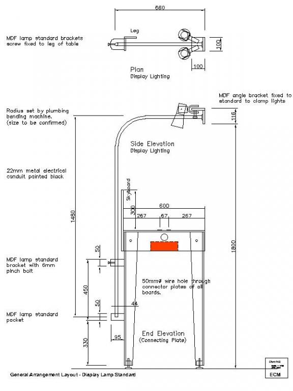
Hi Richie Great, the dim is approx 900mm from the baseboard top to the MDF light mounting bracket. murrayec
-

NDMRS Exhibition 12/13 April 2014 - Please note venue will change!
murrayec replied to steventrain's topic in What's On?
Hi Dave I hope it show went well for you, I like that combined steam thingie. Little steam engines are cool murrayec -
Hi Dave Excellent, I've posted up some views of the Seapoint Martellow Tower on my workbench thread - http://irishrailwaymodeller.com/showthread.php/2346-murrayec-s-Projects?p=49204&viewfull=1#post49204 Here is a taster... murrayec

-
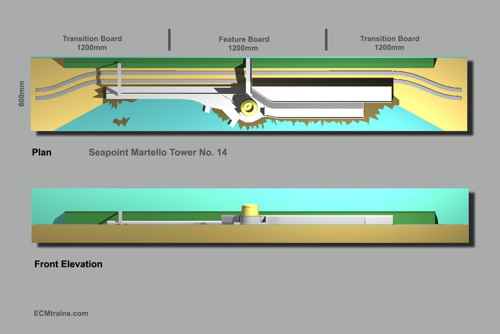
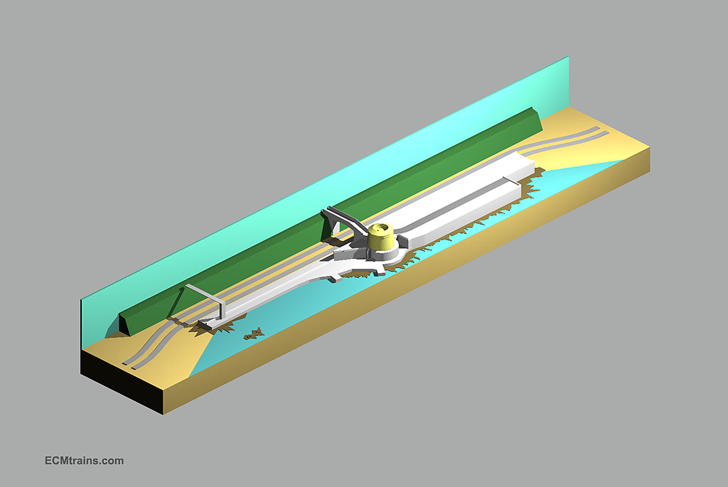
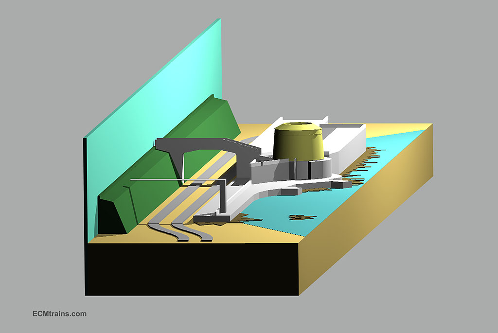
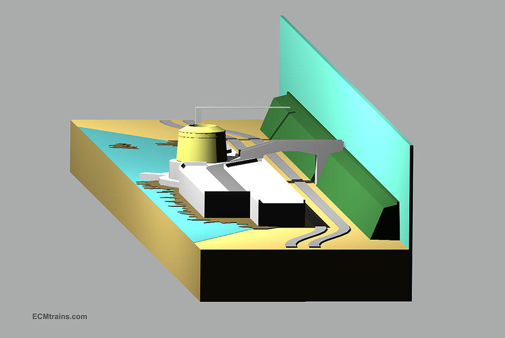
Refer to Volume 1 at; http://irishrailwaymodeller.com/showthread.php/2346-murrayec-s-Projects?p=34623&viewfull=1#post34623 Hi All I have been developing up a baseboard layout drawing for the Seapoint Martello Tower, its not yet complete but I thought I would share some images on the layout because its based on the 'Modular Baseboard System' see thread; http://irishrailwaymodeller.com/showthread.php/2465-Modular-OO-Layouts?p=37052&viewfull=1#post37052 The layout runs across three 1200x600mm boards, two transition, and one feature boards, though the transitions have some of the feature on them. The two main line tracks move to the back of the feature board to allow for Seapoint features and the tower to fit, incorporating 4th radius curves to do this. This design complies with the Modular System. As you can see I have a lot to sort out, this is why I prepared these renderings from the drawing- sometimes its easier to see things in a mass model than line drawings. (no, heirflick that's not a religious dancer) The Tower stands to high but I don't have enough space to get the ramp over the Ordinance Bridge longer to lower the tower. I may look at lowering the embankment and bridge- though the bridge is set up for catenary! Another idea is to have a front extension to the board to give a bit more space but dont really want to do this, I'd rather stay within the 600mm module. As I have said before, this is a truncated Seapoint layout but I think there will be no doubt as to the scene location..... murrayec
-
Hi Dave Thanks, I thought there was something funny about it as it came in as text! Scoot back a page and see murrayec
-
Hi Thanks guys for the comments closetmodeller- an electrical pick-up pantograph would be great, but both the track and the catenary would have to carry power which adds more complex matters to peoples layouts. So far all DARTs sold run on tracks without catenary- though I could be corrected on this. Some intend to install it. I looked at powered pantographs and they have their problems with their springie joints and the like. The best ones are the diamond type as seen on the German models but so far I have not seen one like a DART murrayec
-
Hi All We have been very busy over the last few months and not had a chance to progress things, so here is one.... David Holman, in his blog today was discussing layout display lighting, its something I was thinking about on the Modular System and he prompted me to do this. Here is a sketch of a lighting standard system that could be used. I do not think it should be mandatory, up to the modeller to decide. The idea is a post up from the back of the layout and out over the layout with a bracket fixed to take clip on lighting. I reckon only one is needed per board, as two lamps can be fixed to it. I did a quick search and found Ikea have a clip spot lamp 'Lagra' (no bulb) for €3.50, the lead is 2m long and it can take an LED bulb. The standard is fairly simple construction with off the shelf parts- MDF, 22mm metal electrical conduit with fittings to suit, and screws n bolts. Fire back comments if anyone has ideas.. I am just completing a drawing for my Seapoint Martello Tower layout, which is based on three boards- two transition boards and the feature board. The transition boards throw the track to the back of the feature board so that the Tower and a bit of water can fit to the front. I will post up a drawing when complete murrayec
-
Hi David Excellent tip for display lighting a layout- we never thought of it for the Modular Layout System featured on this forum. I have to put on the thinking cap and prepare a drawing. You've sparked an idea... Thanks murrayec
-
Hi That's very well done- 'A handy man with a bit of Dirt' murrayec
-
Hi On the Hibernia... Here is a slide show motion study of the Bell-Crank and Drive Rod. Prepared from screen captures of the drawing for the loco model. It was prepared to prove the crank and rod would not foul the chassis. [video=youtube_share;PfJLEgPB4Ho] It's a mad looking thing- one of the main features that attracted me to the locomotive. murrayec
-
Ah! There yea go murrayec
-
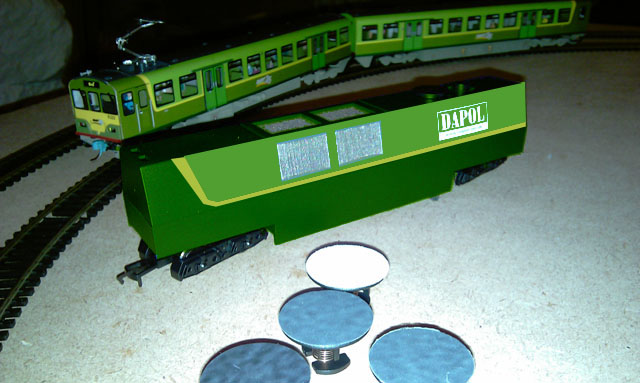
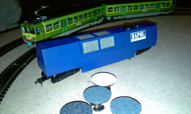
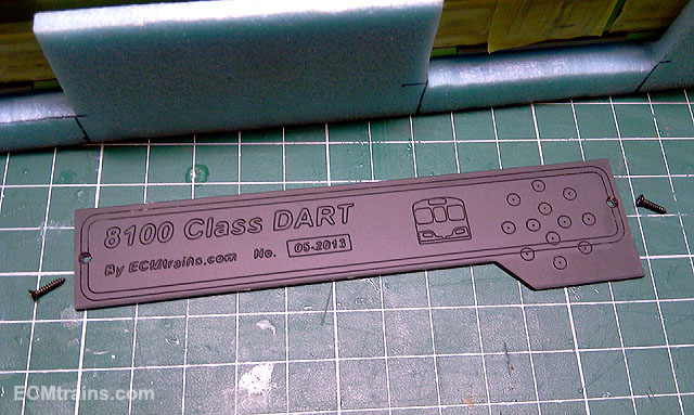
Hi Dave Look at what I got today- to save me fingers! I wonder could I do a Glenderg on it and turn it into a DART coach? murrayec
-
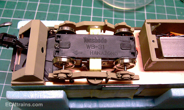
Hi I was just looking back over the thread and had a thought on the inspection car motor- a Thenshodo spud has a lower profile than the BB motor it may fit the purpose better and they are cheaper. I use them for the lower profile reason, I do not have to cut a hole in the floor for the motor to stick up thrugh for the BB, I just drill a hole thru for the screw on the Thenshu..... couldn't resist that!! Branchlines again for spuds murrayec
-
Hi All Here is a short video of two DART25's on the test track... [video=youtube_share;ZvqIV9ozQ6o] I run them for a few hours, starting with Mr Rice's recommendations- run slow for 10 mins stop and let the motor cool down, then run other direction slow for 10 mins, stop and let the motor cool down. Repeat this until up to half speed and then add the van and run both directions for 10 mins at half speed. Any problems that show up in the beginning stages are sorted and final running in is up to the owner. It takes a few good runs to bed in the axle bearing bushes in the bogies Both ran very nice from the onset murrayec
-
Hi enniscorthyman Well done on the bubbles, they look amazing in the outdoor shots- looks like they've been in service for years, i think its the wood that adds that character. I see you have a few more to do! Branchlines are the guys for Blackbeetle motors if you cant source it elsewhere murrayec
-
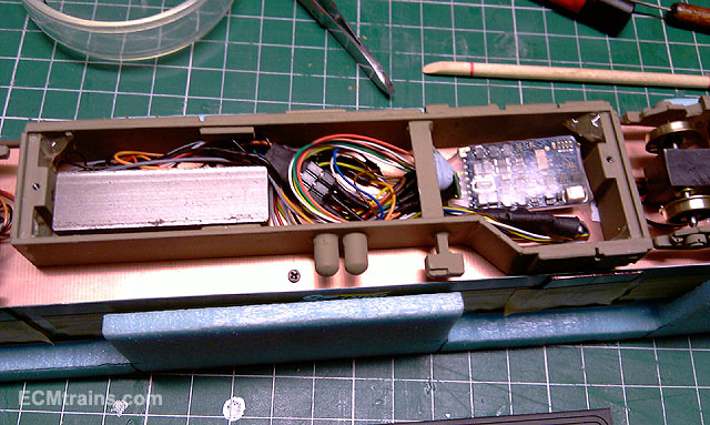
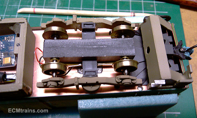
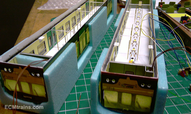
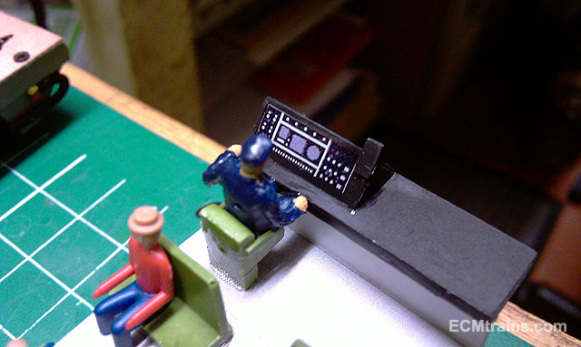
Hi Here are a few shots of the business side of the DART model. Sporting my new cast white metal boxing and screw on lid. As you can see its getting pretty tight in there with chip, pantograph arc light control, socket and connectors, and an MS weight! Yet to try and fit a speaker.... The skirts are cast white metal also. murrayec
-
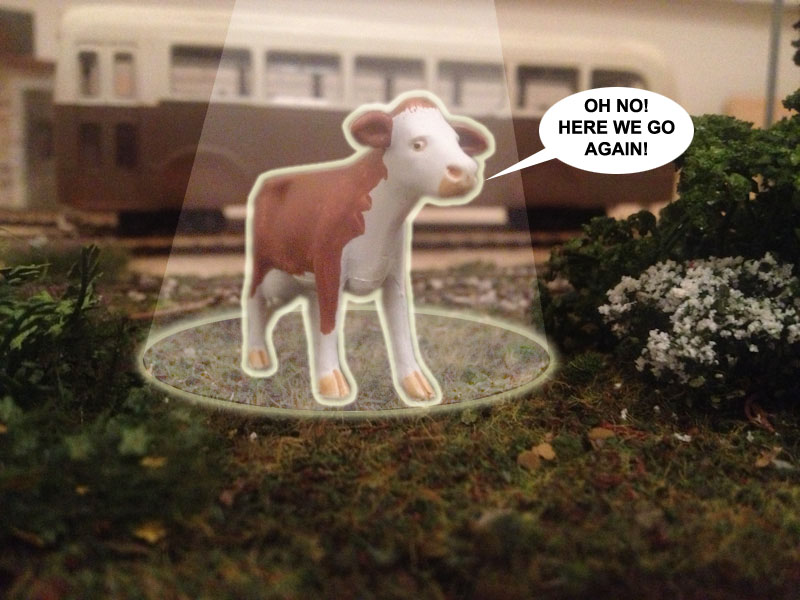
Hi Phil Love the puddle and point throw, as said before these little additions have an amazing affect on the scale also I see the cow has elevated status, very nice murrayec
-
Hi Tony Looks a great layout, I was just thinking the same thing- you have some tight points turns there as BosKonay noted, get your layout into some track plan program and see what happens! The stobart rail 201 looks great, I'd do it, but remember its fictional murrayec
-
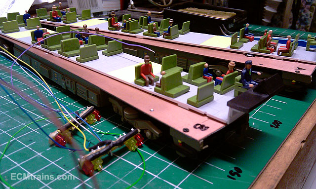
The standard is 24 passengers. They are a nightmare, always arriving late, leave their feet behind, and require Trans7 to stay in place.... murrayec
-
Hi BosKonay You've come out! I'm starting on yours next week in an initial batch of six, I'll work on the six until I'm frustrated again and then work on individual orders at a time. Construction will go a lot faster this time as I have some new jigs and things to help. murrayec
-
Hi Broithe Not fully, the driver is standard but the passengers are an option. This driver is Oisin McDonald by the way, they are named! murrayec
-
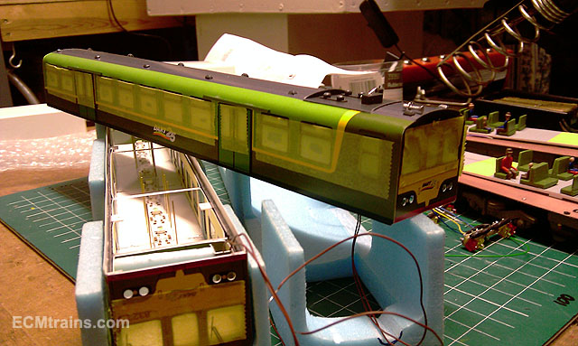
Hi All Just went over the 50,000 views today, I'm chuffed... Here are a few shots of DART 05 just coming to completion Test running in the morning and off to its owner murrayec
-
Hi jhb171achill I do like the art of graffiti! but not what's available to view on the towers and the whole line from Bray to the city, and further. There is not a gram of art in it, it's just vandalism.... murrayec
-
Hi Walter Excellent, you are recovered, I hope to 100% Look forward to seeing you Sunday murrayec
-
murrayec