murrayec
-
Posts
2,731 -
Joined
-
Last visited
-
Days Won
70
Content Type
Profiles
Forums
Events
Gallery
Everything posted by murrayec
-
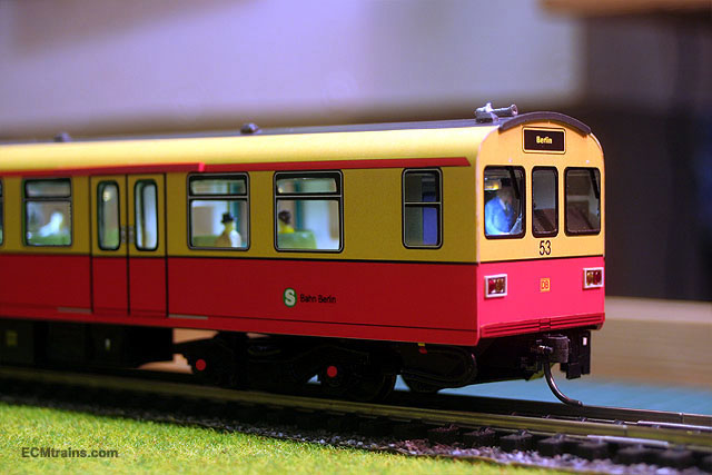
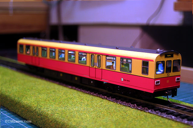
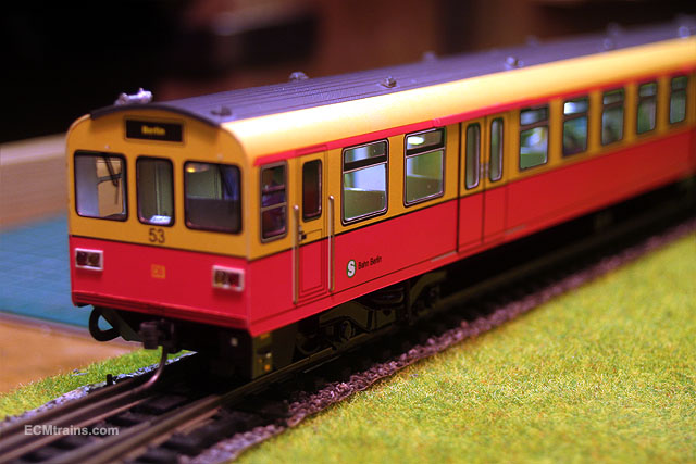
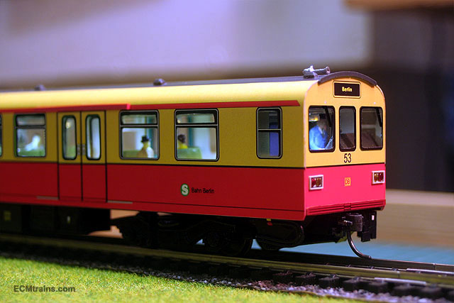
oops! Just noticed I meant to include red hubs over the wheels on the above photos;- Like this; murrayec

-
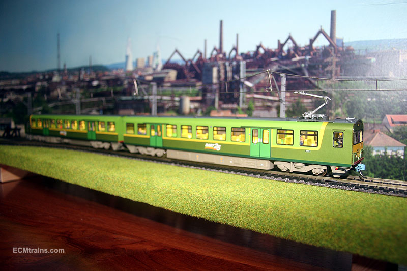
Hi All Here are a few photo composites of the S-Bahn motor coach, prepared for a chap whom is placing an order. The images are of an old body type without windows overlaid on the DART interior to represent a windowed S-Bahn. The red colour is slightly washed out by the lighting in the workshop but I think it is a nice livery in the flesh. You'll notice there is no pantograph- they use a ground supply line on the S-Bahn which connects into the bogies on a number of coaches throughout the train. I think its such a pity we didn't go this way when introducing the DART in the 80's. Catenary is such a mess! murrayec
-
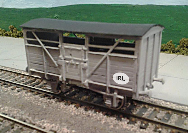
Hi AP It's all looking great, well done. The yellow wagon is cool murrayec
-
Hi I have been asked by a member to show how sweat soldering is done, I will post a few photos and explanation when I'm doing the Hibernia drive rods. But in the mean time here is a link to an over-view to soldering which may help, it includes a bit on how to sweat solder;- murrayec
-
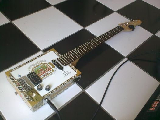
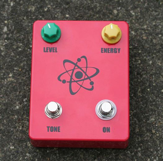
Hi Guys Thanks for the great comments Hey Broithe, here is something further- does this count?;- A friend makes these beauties and I assist with hole drilling, decals, ideas and holding! The Cigar Box Guitar's he makes are deadly, they look great and sound the part. The fuzz box is his own design and he calls it 'Atom Fuzz'. Check out 'Helium Dog' on facebook if you want to see more. murrayec
-
Hi Dave That's excellent, is this the plan for the Kildare back yard? murrayec
-
Hi Patrick I just could not resist; I love your layout, especially with the lighting and the black surrounds, its great murrayec
-
Hi Nelson Nothing wrong with those photos, I can see how nice it is from here. Very nice murrayec
-
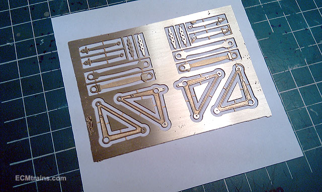
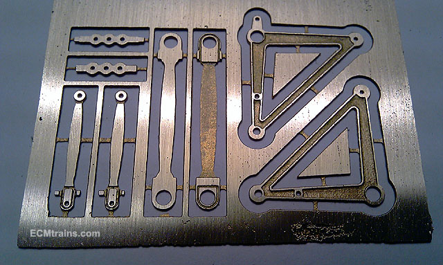
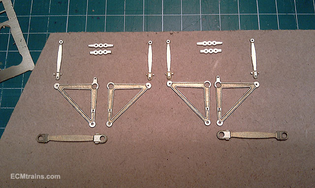
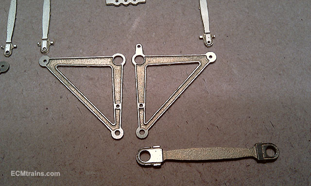
Refer to Volume 1 at;- http://irishrailwaymodeller.com/showthread.php/2346-murrayec-s-Projects?p=47583&viewfull=1#post47583 Hi All Here are a few shots of the bell-cranks, drive rods, cross-heads, and cross-head drive rods, - etched in .5mm brass, just out of the acid bath. It took me a few goes to get it right, its a fine balance of the right coating of photo resist, the correct UV exposure, and a strong mix of acid! Some detail has been lost on the drive rod ends but these parts are good enough to work with assembling the test model, I'll make adjustments to the print tooling and acid mix next time around. The parts were etched from both sides so that the main drive rods and bell-cranks have a bit of 3D, the drive rods are of two components which will be sweat soldered together to give thickness. Also etching from both sides reduces the edge cusp- the parts stay close to size, so less edge cleaning up with a file. The magic etching formula was used in the print tooling for parts over size and all holes are etched under size. Next on the list is the bell-crank main bearing housing, when that's complete the drive and crank system can be erected, the motor installed and a test run of the system!! murrayec
-

Drumm Battery Train footage
murrayec replied to Garfield's topic in Photos & Videos of the Prototype
Hi HF While doing a bit of reference reading last night I came across some Drumm Battery Train info in 'Locomotives of the GSR' by Clements & McMahon;- Mr Fry built a model of Train C, it's a bit more modern than Train A & B, with streamlined ends. Though apparently the actual train was built differently, according to C&M Mr Fry was an employee of the GSR at the time and had access to preliminary design drawings. The batteries in one coach weighed 15 tons! It would seem the demise of the system was due to charging time and not enough seats at peak hour traffic. They tried different configurations by connecting Train A & B together with a Compartment brake third in the middle but again charging time at 30mins held up the platform- they decided to pull the train by steam loco's at peak times. It was found that the trains were more expensive to run than steam. Power shortages meant the trains could not run In the end they dismantled the drive system of Train A & B, removed the batteries and used the units as coaches. Some of the equipment was used in Train C & D, but this proved to be a mistake. It all ended in 1949 Interestingly C&M note- the trains were so quiet when running, there were a number of collisions with people trespassing on the track! I personally like the A & B trains, they have a kind of Victorian elegance and though modern at the time. murrayec -
Drumm Battery Train footage
murrayec replied to Garfield's topic in Photos & Videos of the Prototype
Hi My Dad was fascinated with this invention at the time and regularly mentioned it when we talked train. When he heard way back that I was going to make a model DART, he asked me to make him one of these for the display shelf. He had taken photographs of the train and he even did two sketches of it, but we never could find them in his collection. Sadly he past away 3 years ago, but in his memory I have added this train to my list of models to make before I move on to the big train in the sky..... murrayec -
Hi All Thanks for your comments Hi waffles, great to hear from you, have not seen you post of recent. I hope all are well and the study is going well murrayec
-
Hi Colin Thanks You'll find the price list here;- http://irishrailwaymodeller.com/showthread.php/895-New-DART-8100-Model?p=45210&viewfull=1#post45210 murrayec
-
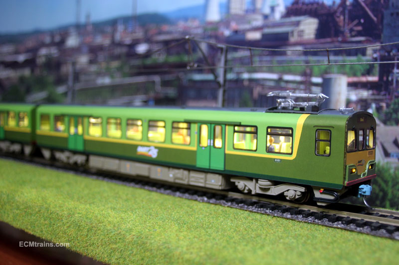
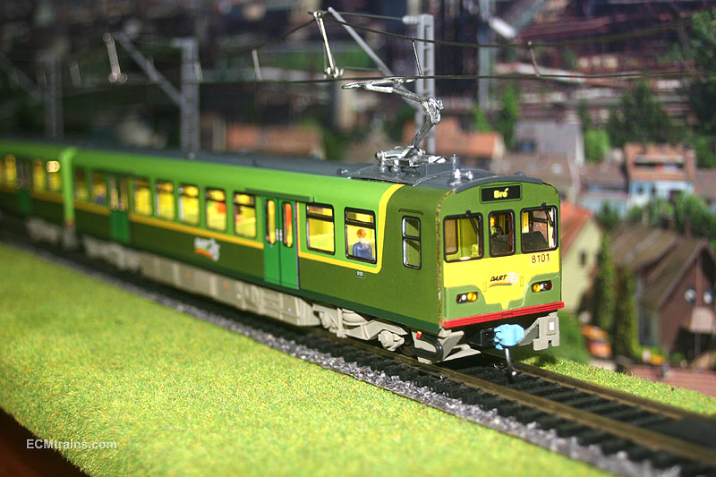
Hi All Here are a few shots of Order-01 DART No. 8101 (the first!), which was completed this week and on the way out to it's owner. There are now 17 Model DART Trains completed. I have now commenced into the next batch full time! Some items have been fabricated over the last 3 months, all stored away in boxes and jars-n-things. This new build of 8 sets includes orders;- 08, 12, 13, 14, 16, 17, 18 & 19. The sets will be released from the works according to their order numbers. My apologies to people whom have been waiting several months on their trains, I underestimated the time it would take to make the tooling for the builds and the time it takes to assemble each order. As I have mentioned before, now that the tools are done this new build will be quicker. murrayec
-
Hi Kirley Yes, 13mm seem to be a hard one to get! All the manufactures have omitted 13mm, it's probably not to scale. I was doing the same recently and had to settle for 14mm Romford from Branchlines. murrayec
-
Hi BGM I would have to say, because RAL 1021 ref was my own personnel choice, give it a go! If you are only running the 121 on your own layout it should be fine. If you are going to hook up with others then their may be a difference! I would suggest;- when you decide and have the loco painted post up a photo with your colour ref's attached and then others may follow. Hey- post up a photo now and give us a look, would love to see murrayec
-
Hi Excellent photos, I love the White Bush Jigger. Some things that people do with other things are amazing! I think I would be tempted to turn the steering wheel if I was in it. murrayec
-
Hi Another thing... Tom Ferris's book 'Irish Railways A New History' has a couple of 121 pictures, you can see them at;- http://www.amazon.co.uk/Irish-Railways-A-New-History/dp/0717142914 use the 'click to look inside' and scoot past the index and the pictures start- no. 133 at Amiens st is first and no.'s 124 & 126 at Inchicore are later. The later photo is interesting, the note says the photo was taken in 1961 shortly after delivery- it's a b&w shot but I reckon there is no yellow on these two, even no yellow wasp stripes. I think this was the first grey as delivered- could this be the grey/silver, could be wrong though it's hard to tell in a b&w photo! murrayec
-
Hi Dave That's just brilliant, you have done an amazing job on this layout and it's not even yours. I hope the client really appreciates what you have done here, setting up the beginnings of a really fine layout. Hours of fun ahead. murrayec
-
Hi BabyGM I looked into this one many moons ago to scratch build a fleet of 121's, though have not started on it yet! Here are my notes on the Grey-n-Yellow livery;- Body Colour's Grey & Yellow Option. Tom Ferris describes it as Silver/grey - Ideas on grey = RAL 7035 Light grey RAL 9006 Light silver grey (darker than 7035) BS 00 A 01 Light grey (lighter than 7035) Ideas on yellow = RAL 1021 BS 10 E 51 I like this shot of the 121, because it's on a dull day with no mad sun reflection and it shows the grey/silver look- this was my choice picture so I marked RAL 9006 for the grey. http://eiretrains.com/Photo_Gallery/Irish%20Locomotives/121%20Class/slides/126_196106086_0001_CC_JA.html murrayec
-
Hi A well known modeller was employed recently to re-wheel some of the diesel stock and he told me that some of the original Fry items are to fragile now to run, hence they were displayed in cases. It is unfortunate that some poor models were added to the layout, but I think it was done with good intentions, a way to keep models running on the layout and preserve the original ones! I agree with Glenderg- we should throw lifelines, if we all sit back and grump nothing will happen. Send an email to the minister's office, the link is above. and do it again in a couple of months. murrayec
-
....Oh and Replacing the wheels;- if their not a full set with bearings attached you will have to dismantle the existing wheels to get the bearings off and use a back to back gauge or a calliper to get them gauged again. Try Marks Models as suggested earlier, but it may be quicker to get them from Bachlines, Markits, Ultrascale, or Sharman Wheels. One thing about using IPA to clean wheels, if you have a little accident spilling it or it gets in the wrong place it can be problems for paint work, especially acrylic paint or varnish murrayec
-
Hi irishthump Have you tried giving them the good polishing yet?, maybe they are scratched from the previous owner! and as Old Blarney says about the fibres.. I usually clean out the bearing and wheels of oil before using the brush, then blast with air at low pressure, and then re oil. If it still happens and you are sure about the track then new nickel plated wheels might be the only way murrayec
-
Hi Glenderg It's here, well at least 4 months ago it was;- Dublin Writers Museum | Fáilte Ireland | | 18 Parnell Square North | Dublin 1| T: +353 (0)1 8722077 W: http://www.writersmuseum.com Curator;- Robert Nicholson murrayec
-
Hi irishthump The wheels on my 141's are brass, newer models seem to have a nickel coating but I can see brass coming through this finish. Don't use wet n dry or emery paper to clean them, this makes them pick up more dirt, only use a scratch pen. If its the first time with the scratch pen give them a really good going over to get the surface smooth again. If they still pick up dirt you will need to look at the track murrayec