murrayec
-
Posts
2,758 -
Joined
-
Last visited
-
Days Won
70
Content Type
Profiles
Forums
Events
Gallery
Blogs
Community Map
Everything posted by murrayec
-
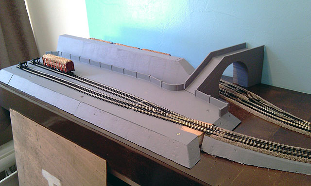
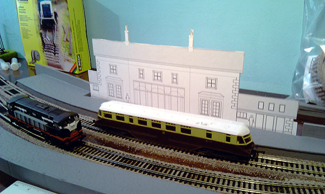
Hi Here is a small update on Closetmodeller's Greystones Layout, work has been progressing slowly but we are having fun;- Track is finally down with the ballast now to be completed Blue sky painted in and everything under-coated Closetmodeller cut and mounted the preliminary drawing of the station building to get an idea Finally Closetmodeller's vintage steam loco! Eoin

-
Hi kevrail has hit on it! work on what we want and when we feel like it I'm afraid to make a list it would have to go back about 20 years or more! Eoin
-
Hi Just gets better and better When looking at the photos I keep expecting to see the figures move! Eoin
-
heirflick See the link on this page http://irishrailwaymodeller.com/showthread.php/4533-Silverfox-D-Class-Shunter?p=68518&viewfull=1#post68518 Eoin
-
Hi I should have said with my post above;- I love Silver Fox models, sure they are making models of Irish, and close to Irish that nobody else is doing. I have two Class C & A SF kits I'm currently working on chassis for- this appears in another thread on the forum. I'm also making C & A chassis for other peoples SF kits Silver Fox rock for me Eoin
-
Hi Weshty It's an internal recess for the hand break handle- the break shaft runs up tight to the back wall of the cab with a single arm handle on top, when rotating it one would bash into the cab back wall so the clever design department came up with this excellent solution!! Eoin
-
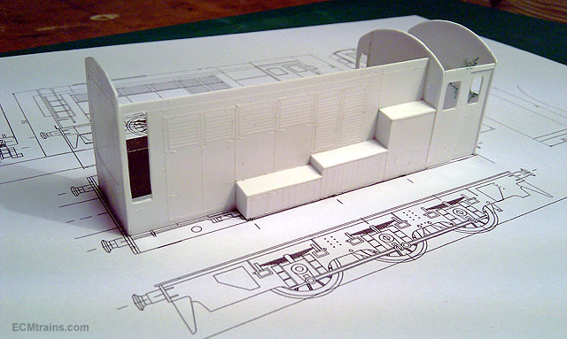
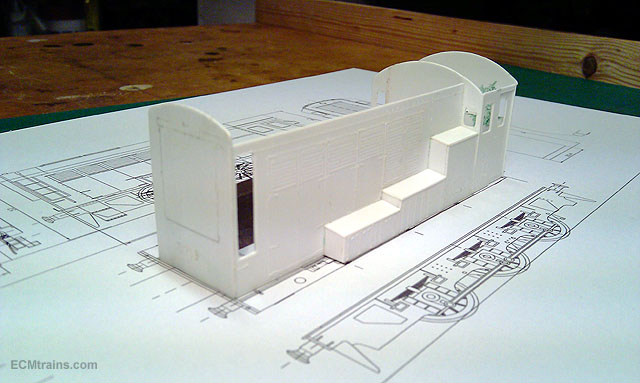
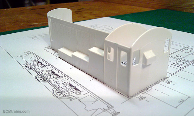
Hi Ah! the old Class 08- when I was 9 or 10! I had a fleet of them painted Valspar orange bought in Wigadors!- memories... Though this tread reminded me that I'm working on a D, not touched for a year or so and still at prototyping stage, I grabbed the box down and took a few shots;- Mine is going to be green Eoin
-
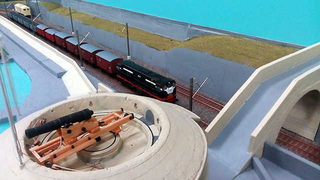
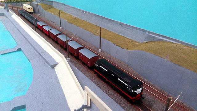
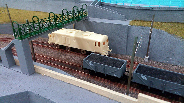
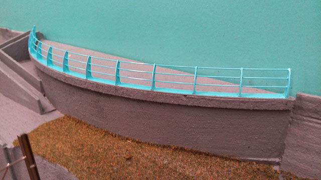
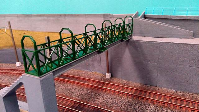
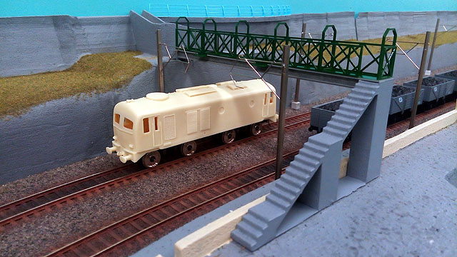
Hi All We had the Modular Seapoint Layout at the Wexford Show last weekend and Dave took a few shots of the work in progress;- Dart cantenary spars have been installed. Viewing area handrail installed. Upper section of the footbridge installed. More detail to the cannon added. Eoin
-
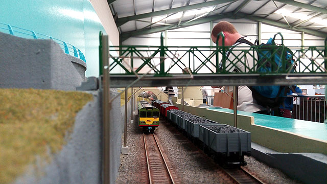
 Hi All Here is some footage of the show taken from Baseboard Dave's quad-copter;- and a few shots from the ground on Monday morning before the show opened;- Eoin
 -
.....that disapproving eye is for you after knocking over his vodka, and look the other one is on the Bud! priorities what... Happy Easter all Eoin
-
Hi All Great to meet all who came over to say hello today, with all the talking and things to do I never got to take a few pictures! Yes lots of layouts- leaning to the N Gauge side, and loads of things to buy!! A well presented show and very easy to get around- hopefully more will come tomorrow! I picked up a nice little N Gauge white metal kit of a 45t Boom-handler / Reach-Stacker;- Looking forward to seeing and hearing a sound Class C loco a forum member is bringing in tomorrow. We have to invent a barrier system without those mad feet that everyone trips on, their disastrous! Hopefully will get a few photos Eoin
-
Hi Walter Lovely stuff, I love the road paving on the one above, and the van- their lovely models Eoin
-
Hi Yes it was a great meeting of the Gauge O Guild, we get to see some of the work in progress on the models and discuss ideas n problems. Also to see some excellent models running on the layout as Warbonnet's expert photos display above. Thanks to the MRSI guys for hosting Eoin
-
Cab light problem with MM 201s and Hattons DCR-21pin DCC decoder
murrayec replied to declan64's question in DCC, Electrics and Electronics
Hi Guys Here is some 'Pudding', I recently did some tests on this subject;- Eoin
-
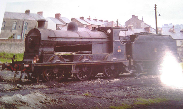
Hi Guys The 4F is a ringer for the SG & SG2 there were 15 of them which CIE had 8. Main things to be done is; Remove the top of the Belpare boiler and make the sides flush. Add sand boxes to front spalshers and fill in between middle and rear splashers. Change the dome to bigger and rounder top. Install ovely windows in cab. Remove hatch on roof of cab and fill. Cut back overhang on cab roof. Remove railings from tender and extend up sides in solid. You now have a SG2 with some beautiful detailing!! Eoin
-
Yes One example in North Wales railway- a restoration of a narrow gauge loco had an all welded firebox and boiler installed, the design was based on the traditional fire tube principal without a water tube firebox and boiler, and it incorporated some modern design concepts- it is written that when they completed the loco it exceeded all expatiations by maintaining full boiler pressure for over an hour on two domestic-sized buckets of coal- when running, pulling a large load they don't carry coal they just stoke up at the end of each hour run. If the water tube system was used efficiency would be greater again! but this construction moves to far away from the loco's original design and was not used- heritage loco. And there is one problem for the modern system! most guys working in this field are historical groups and stay within the loco's original design, implementing some modern concepts for; efficiency, safety and ease of use, but staying within a historical control. If a modern oil burning system was used or the instant steam system I mention above- thing would only get better... I believe in the States some of the loco restorations are implementing oil and gas burning systems, the 'Big Boy' I believe is one? It would be interesting to see data on the efficiency now and back in its day to see what kind of improvement has been done. Though with this loco its power to weight ratio is crazy and they are working with old style tech and its not new! In my discussions on the instant steam boiler system it was estimated that the loco could run full time for one week on two large domestic cylinders of gas. A number of assumptions were made here as the full system was not designed and we were only looking at theory and viability. Eoin
-
Hi Live Steam! A very powerful gas that can do huge work and be generated by simple means- it's just that the old boys that tinkered with engine design stayed old hat! When British Railways built their last boiler for their last loco 'Evening Star' although bigger it was not much different from Stephenson's 'Rocket' but with a superheater attached. Bullied was the man, he was one of the first to adopted welded boilers, and welding throughout the locos construction, cutting manufacturing costs by half- he was before his time but to late in the competition with diesel and still slightly old hat. He was working with a grossly low thermal efficiency system mainly due to the boiler design. He was to early for new advances in the manufacture of water tube walled fireboxes and other more modern build methods which ultimately led to high thermal efficiency steam locos fired on oil and gas.... Most of this work carried on through the 60's, 70s & 80s in Africa, China & Brazil or Argentina- guys like David Wardale & Dante Porta. How CIE ever thought that turf would work with the old boiler design, with it's low thermal efficiency using coal to start with! About 2 years ago I with others did a feasibility study on building a replica steam locomotive- we do have dreams!, I spoke with a few engineer's in England and found a company who were involved in making the wheels for the 'Tornado' A1, a very nice helpful man- he even came back to let me know that they still had the mould blanks to cast the wheels we needed! He put me in touch with a company that manufactured steam boilers, the kind we put in office buildings and Hospitals to work heating systems run on gas or oil- very popular in Finland, high in efficiency. They manufacture a product which is mobile, a self contained burner and boiler in a small handy package that fits in a small car trailer, they gave me the spec of the machine and after a discussion with the engineering wheel man, a few calculations done he concluded that the system would produce plenty of steam, to much for what we wanted to push! It's a very efficient system, it works like a power shower- fires water into a container in front of the burner and instantly turns it into high pressure steam. No fire warm up time, just wait for a head of steam and your on the regulator. The boiler company were to get back to me on the suitability for our application, the project sort of fizzled out and I never chased them up! I know this is not the same as burning coal, making noise and getting a black face, but live steam in modern design systems is 2 to 3 fold more efficient than the old locos- what a pity the old boys couldn't in 100 years change from Stephenson's original design. I still love them though, beasts.... Eoin
-
Weshty Nice one, knew it was something like da!....... Eoin
-
Original SLNCR history (Sprinks, 1970)
murrayec replied to jhb171achill's topic in For Sale or Wanted
Hi JHB Just browsing David Holman's article in Railway Modeller and up pops this post on me screen...... Like the new avatar Eoin -
Hi All If you mess about with fibre optics for lights on your models- get down to Tiger for their 'LYSFIBERLAMPE' for €4.00- one of those dodgy droopy 60's fibre optic lamps run by battery- but it has about 237! optic strands sticking out the top that would keep a modeller supplied for a life time! Eoin
-
Hi Me to, looks really great and a fine article Congrats David well done- I see you had the same turntable problem with the bus and luggage wagon! Broithe - got to get yourself a brolly! Eoin
-
Hi Tony Isn't the English language a funny old business!! Boolean operation your looking for;- Invented by Mr 'Fred' Boolean for 3d solid modelling- adding 3d solids together, subtracting one 3d object from others where they intersect, and creating an object from the intersections of 3d objects!! A way to do doing this is to draw a polygon for the window ope and make it a solid with a thickness greater than the front wall and intersecting it, then use the window ope object to cut-out or subtract it from the front. That is the English version, now you have to find how your software does it. Once you have mastered one window ope- your away, and you will find this operation can be done on multi objects at one time- draw all the windows and then subtract in one go. Only joking about the 'Fred' bit- don't know the mans first name but he was pretty good at maths Eoin
-
Nice one WB Interesting point on the washing machine!!- don't think it was ever used... Eoin
-
Walter Send me a chassis or bring to next show- something in the 20m scale size, I can take a look and think about how..... Eoin
-
Hi All Thanks for taking a look and the great comments Come down to the Carlton Airport Hotel Show next Sunday, it will be there if you'd like to see Eoin