murrayec
-
Posts
2,765 -
Joined
-
Last visited
-
Days Won
70
Content Type
Profiles
Forums
Events
Gallery
Blogs
Everything posted by murrayec
-
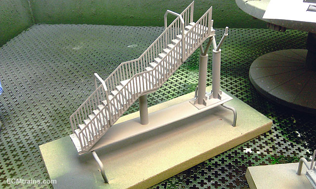
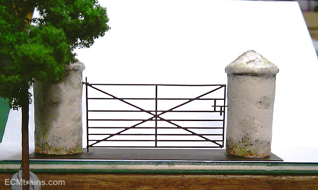
Hi All Here are two shots of items for the layout hot off the work bench.... Handrails for the pedestrian bridge steps are now complete and all is ready to install on the layout This is the gate into the field to access the beach, it's from an SSM etch with foam-cut stone pier posts- old style, not many about any more! Eoin

-

Collectables Toy Fair - Sunday 4th October 2015
murrayec replied to Brian Collins Enterprises's topic in What's On?
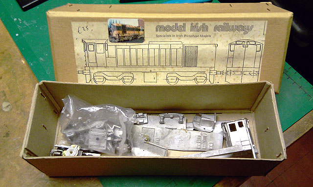
Hi I picked up a nice bargain at the show today-- A MIR 121 Kit for €25.00, cant beat it.... Eoin
-
Hi I saw the bridge in the flesh at the Carlton Hotel Show today, as we now say 'It's a beautiful thing'. By the shots above and all that's going into it this layout is stunning... Eoin
-
Hi BK Just thinking- you may be referring to the footbridge and lifts in one of the earlier photos- this can also been seen in the Tips n Tricks;- http://irishrailwaymodeller.com/showthread.php/4586-Hot-Wire-Foam-Cutting-By-murrayec?p=72001&viewfull=1#post72001 I'll have a few shots of it shortly as the stairs handrails are now etched and is currently in the paint shop.... Eoin
-
Hi Driver301 Beautifully done Driver, it's an excellent layout, a visual feast for the spectator of model rail- the massing of the buildings behind the platform pulls the eye in deeper to the platform and then one finds the view into the subway... excellent, we're in it! I hope your going to be at Blackrock, to see it in the flesh and operating, hopefully we can run the N DART on it? Eoin
-
Hi BosKonay The bridge is cut from insulation foam with the hot-wire cutter and then cut strips of foam are stuck on to create the walls and footpath. A paper template is cut from the CAD drawing to use as a guide for cutting- refer to Tips n Tricks section for home made hot-wire cutter... Eventually the bridges will be covered in printed stone work..... Eoin
-
Hi Dave Firstly closetmodeller's intended running is for the main lines through Greystones Station handling four trains to a time table- Timber Train, Commuter, Other Passenger, and the DART. Secondly closetmodeller desired a layout in liner fashion, for main line work, and not to take over his office room. Therefore the boards are 400mm deep and the sidings had to go otherwise the layout would be to cluttered. The outside siding still exists at Greystones and would have been nice to incorporate, but due to the depth of the baseboard it was omitted, as the station building is more important and we wanted to incorporate some of Main Street of Greystones Town in the layout. Eoin
-
Borithe Was that on the brick cottages on the way to the East-Link, I have the memory of a fish over one of the entrance doors- a Bass I think - it was some time back and I could have the wrong location... We need a fishy section now! Eoin
-
Broithe Perfectly clear..... - 'Earwiggie-Traine-Thingmejig-Hornby-Tension-Lock-Coupler-Things' ......please Sir? Eoin
-
Hi all Just home, yes it was an enjoyable day and great to meet all who came and said hello. Great and surprising interest in the DART, a lot of people knew it from theses pages, and David had great interest in the servo points control system. .......and what about Herbert's 'O' Narrow Gauge Doneygal Railways Railcar models- lovely stuff, I forgot to take photos with all the talking. ttc0169 I thought it was quite refreshing! I didn't see a 141 or an orange thing all day..... Would do that again Eoin
-
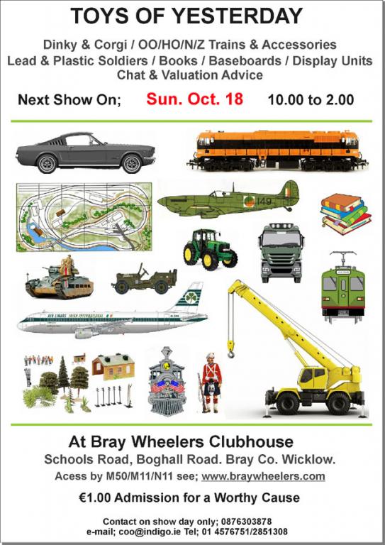
untilAt Braywheelers Club House off Boghall Road Doors open at 10.00am till 2.00pm More info at link below http://irishrailwaymodeller.com/showthread.php/94-Toys-of-Yesterday-Bray-Show?p=75314&viewfull=1#post75314
-
-
Well now, That went very well, as George predicted it was a 'cracking day' in all respects- stunning location, beautiful day, and great attendances. We were busy all day and I did not get a chance to see all the exhibits or take photos even! maybe someone else did and will post them up. Well done to all who ran the show Eoin
-
Hi Myself and David will be there with baseboards, the DART, and other things So as George said- do say hi Eoin
-
Hi john83 When you were looking at wrennie's AEC Rail Car at Bray last, the DART was right behind you... You can see more here;- http://irishrailwaymodeller.com/showthread.php/895-New-DART-8100-Model?p=74567&viewfull=1#post74567 Eoin
-
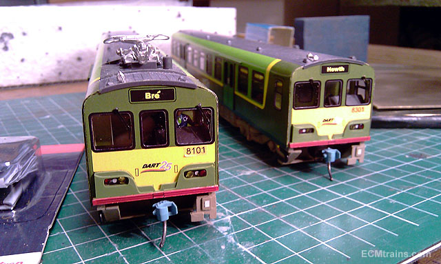
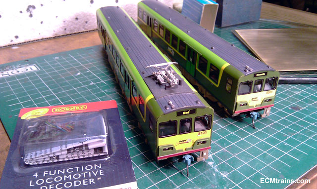
After almost 2 years of service DART 8101 (no. 1) is in the workshops for servicing and re-fit.... ....actually it's an upgrade to DCC. I wonder, does the DART give the same kind of service? Eoin
-
untilDoors open at 10.00 and close at 2.00 http://irishrailwaymodeller.com/showthread.php/94-Toys-of-Yesterday-Bray-Show?p=74565&viewfull=1#post74565
-
-
Hey George Is that hole in the top for the candle? and I see you baked them on a oven tray with loads of icing! Borithe would be proud of you.... Eoin
-
untilToys of Yesterday show is on this Sunday Doors open at 10.00 to 2.00 closing At Bray Wheelers Club House off Boghall Road http://irishrailwaymodeller.com/showthread.php/94-Toys-of-Yesterday-Bray-Show?p=73747&viewfull=1#post73747
-
Hi I support the H&S idea, it goes without question that there should be a system to protect workpeople carrying out a process that potentially could kill or maim for life, not to mention all the other associated ramifications. One of the main problems is human interpretations- a H&S plan is only as good as the understanding the person who writes has of the processes involved in the work and how H&S officers on the ground implement it.... Borithe's example is clear evidence of this. My experiences of H&S is in the building industry and I have seen and experienced good management of it and mad abuse of it. One example is we were constructing a high-bay storage facility in North Dublin, a roof height of 11.5 meters which required a serious section to be written in our H&S plan at design stage for the roof workpeople working at this level. A fall from this height onto a concrete floor is instant death. When it came time to erect the roof beams I visited the site and as I approached from a good 1/2 mile from the site I could see a workperson walking across a roof beam of 300mm with no life line attached, I thought to myself 'a there must be a catch net under, but still there is no excuse'. When I entered the site to my horror there was no catch net and everyone up on the roof had life lines on but not attached to anything! I asked the foreman acting as H&S officer for the works to refer to his H&S plan for construction stage to see that the roofers were complying with it and was told 'a sure that's the way they work, if we ask for lifelines to be attached they will walk off site'!! One other, though not as serious- We were working for an outside contractor on a site, every time we visited the site we were sent to induction (architects are exempt from this) 1&1/2 hours of how to ware our shoes, site cloths, hard hats, and using drills, ladders...... it's endless, well 1&1/2 hours of it. We found out later that the H&S office for the main contractor was under orders to make as much difficulty he could for our design team to access onto the site! The problem with H&S system is humans Eoin
-
Hi Put this up full screen and turn up the sounds Eoin
-
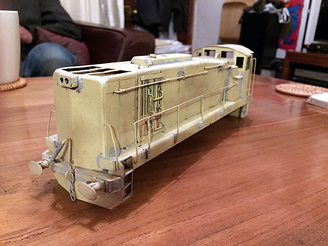
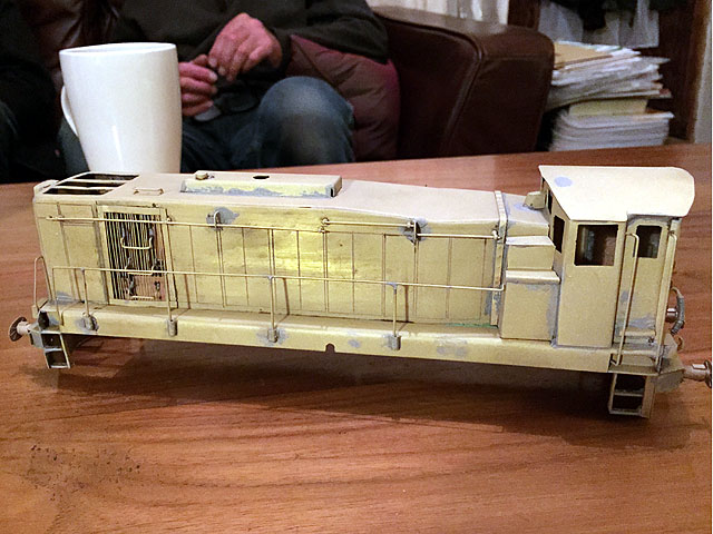
Hi All Here is a few shots of another 7mm model being built by an MRSI chap, from a scratch built kit set-up by that master in the same club. Fresh from the blast cabinet and almost ready to go off to the painting man.... Lovely stuff- I want one! Eoin
-
Hi Yes dave182, I was a slight worried about that one also- but alas, tonight I set-up a Faller Test Road with 150mm, 180mm and 200mm radius bends. The roadway was made from 1mm card 60mm wide, with a 3mm magnetic guide set in. A few stalls at first but out with the spanners and after about an hour or two- it's up and running with loads of power! Slight stalling or tramping on the 150mm & 180mm curves but still makes it around and the 40' trailer needs twice the road - swinging it's ass. The 200mm radius curve looks like the minimum, it swings around it with a slight hint of tramping but looks smooth and needs less additional road The video was taken after a good 1.5 hours running and when I quit there was still power left. Very pleased with the results and thoroughly enjoyed doing it.... Next one has got to have lights.... Eoin
-
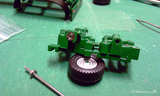
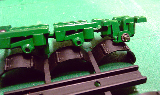
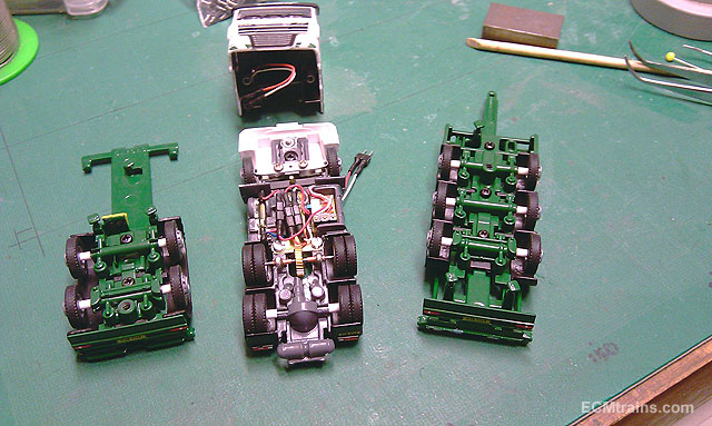
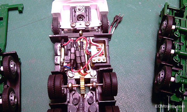
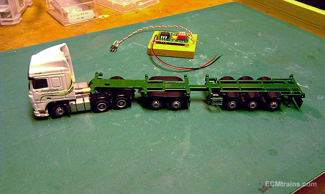
Hi Thanks for watching and thanks for the great comments I got the truck complete to testing stage over the weekend, everything went smoothly except for an annoying 1mm screw breakage and a frustrating time getting it out! This is the trailer axle ball bearings going in, drilled out a 3mm recess to flush fit them. The plan is to set the rear axles of both trailers slightly lower than the others so that the load is on these axles only. The shot above is the front trailer sub-chassis. This is the rear trailer sub chassis getting the same treatment. All new axles and Faller wheels installed, the axles are 30mm long with a 3mm wide styrene sleeve behind all wheels to keep on centre. The non load carrying axle slots were opened up to a very loose fit so the wheels should run on the road with no weight. Just about to bolt it all together in this shot. A close up of the works, the little elec board is tucked into the petrol tank with the charging socket and the ON/OFF switch on-board. On the other side is the reed switch for the breaks- the reed has two outlet terminals when the breaks are on the second terminal is made live- Break Lights! Gears and bushes on the drive system were given some Loctite. That little hole in the steering beam is where the 1mm screw locked up and the head sheared off, this the mounting point for the Faller steering arm. This is the LiPo battery charging circuit with the leads installed, the 3 pin plug has double grounds on the outer pins so one cant plug it in the wrong way round. Charge it up ready for testing. I gave it a quick run on the kitchen floor and it works, it pulls itself and the trailer no problem! it does do bends but will need a bit of playing with, which is best done on a Faller Road. Now the other fun bit- road testing..... I will post the results soon... Eoin