murrayec
-
Posts
2,727 -
Joined
-
Last visited
-
Days Won
70
Content Type
Profiles
Forums
Events
Gallery
Blogs
Store
Community Map
Everything posted by murrayec
-

3d printing Could anyone help me with getting the scale right for 3D printing?
murrayec replied to Josef2000's question in Questions & Answers
OO is 1:76 so your scale factor from 1:1 is .0131 Eoin -
One could go off script and use an elephant instead, it's trunk would be just as handy as the dino's tail....... Eoin
-
-
Hi Kevin, Yes booked beforehand, is it just stuff you are selling once-off or ongoing? Send me a pm about want you want to do and we will confirm back. Eoin
-
Mount the dinosaur on the top and stick the spare collet on it's tail....... Eoin
-
oh, I have one of those kits, somewhere! I forgot all about it...... Eoin
-
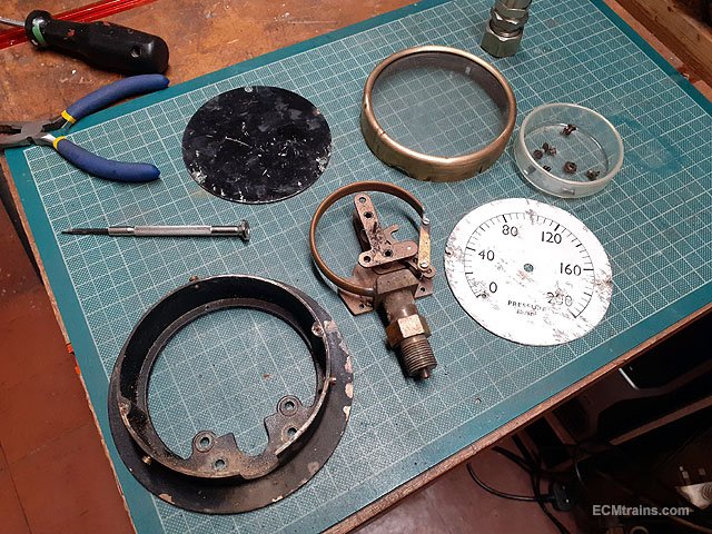
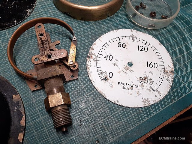
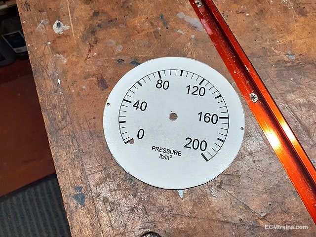
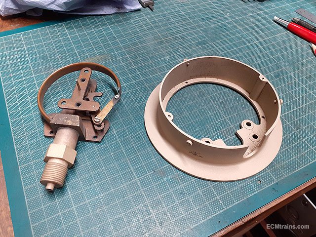
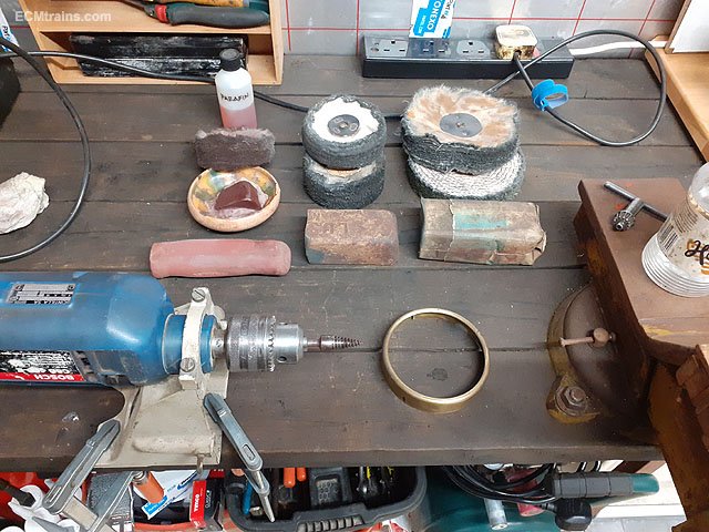
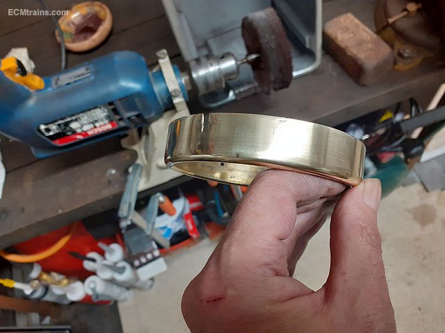
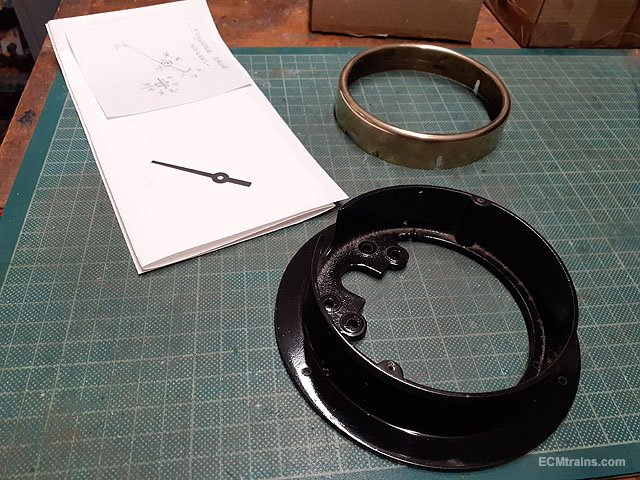
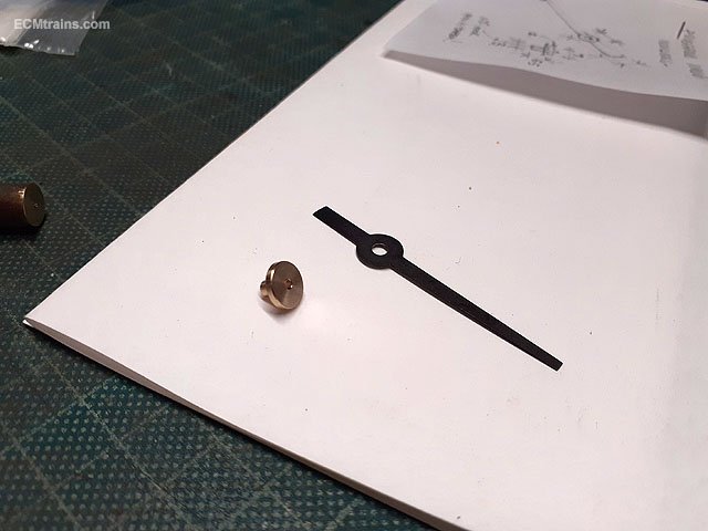
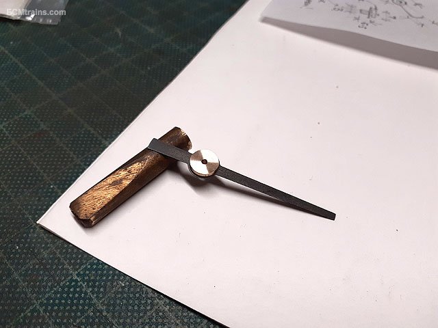
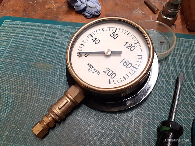
I acquired this gauge many years ago, the glass was smashed, the face badly damaged and the pointer completely rusted away. Large body gauges- 100mm dia, are ideal for steam boiler pressure testing, much more accurate than the smaller type. I started restoring it a few years ago! but recently finished it;- This is the new face made by scanning the old one into Autocad, drawing it up anew, printing it out on heavy paper card and spray lacquering it to seal the paper. It is mounted on top of the old face when reassembling. Sand blasted the outer body and the exposed pipe fitting. Body spray painted, the new pointer was cut from thin brass sheet and chemically blackened. Polishing setup for the brass rim, my polisher is a pistol drill mounted on the bench. I used Luster polish first and finished with Rouge n paraffin. Polished A new brass ferrule was turned up on the lathe. Stuck together with Loctite 603, the ferrule is a press fit onto the pin of the pressure mech, the pin is tapered so the ferrule locks on. Reassembled, the new glass was made from 3mm perspex sheet. I now need to pressure test it against a known accurate gauge to see if it needs adjustment, but I will hang it on the wall for the moment...... Eoin

-
- 10
-

-
I believe Dave is unwell and the company is closed at the moment, I hope things work out OK..... Eoin
-
Or Use Deluxe odourless super glue (no blooming), the green label one, remember not to glue the top rail into the back of the cabs so that the body can be removed easily! Eoin
-
until
-
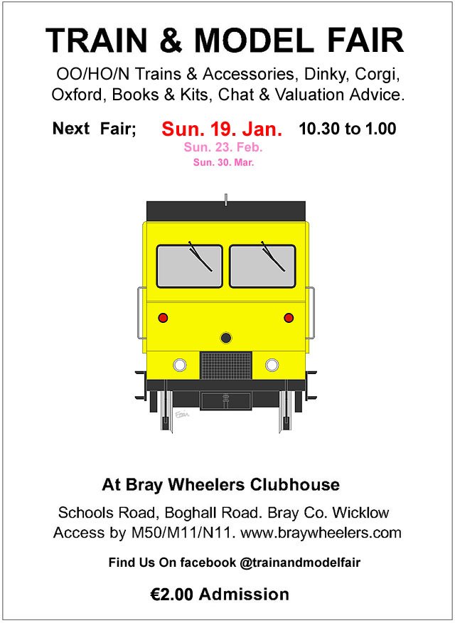
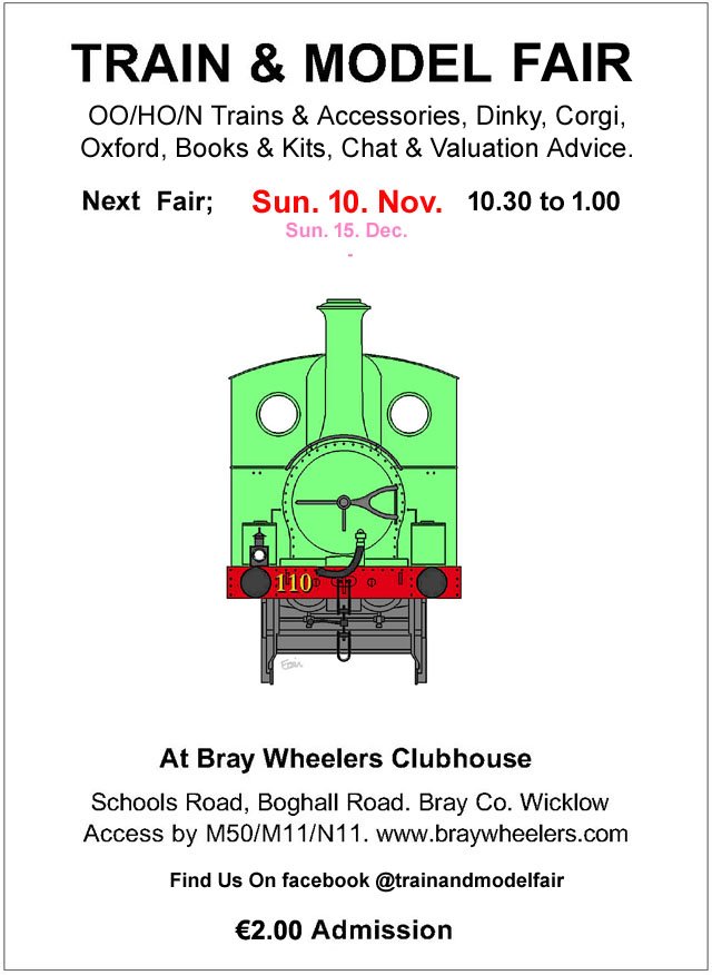
Next Fair = Jan 19, 2025
-
Some things to try;- Is this happening with other locos? This would indicate the track or the controller is the fault! Try running them on a friends layout. Try running them on a separate/isolated track that the controller is only connected to. Reset the DCC chips to the factory defaults. Remove the DCC chips and run them analogue, if they run the chips are at fault. Eoin
-
Hi JasonB, So sorry to hear the story, I was wondering what had happened....... You could setup a quick temporary board with two 8X4' sheets, lay some track and run trains? Then in the future revisit Petersbridge when the above is a distant memory. To the future...... Eoin
-
KMCE had mastered 3d printed pointwork but sadly is not with us anymore..... https://irishrailwaymodeller.com/topic/7108-kmces-workbench/page/10/#elControls_221856_menu He did give info on his track making in some of his threads like above Eoin
-
Sad to hear. May he rest in peace.
-
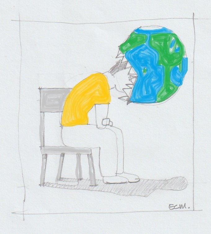
''Endless annoyance at the world''
-
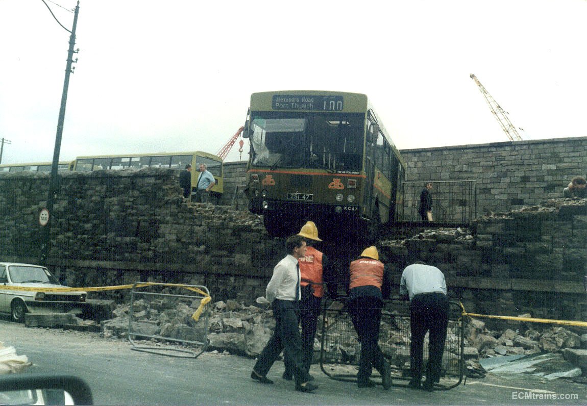
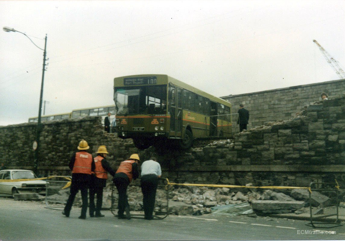
Came across these in my Da's photos;- Connolly station back in the 80's Eoin.
-
until
-
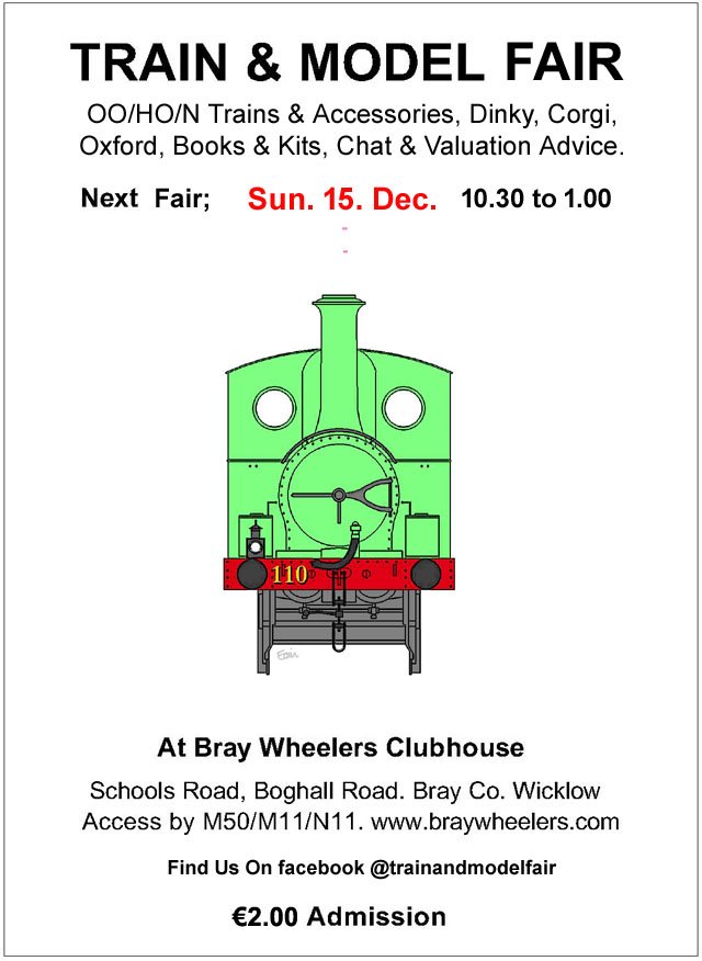
The last Fair of 2024, not to be missed;-
-
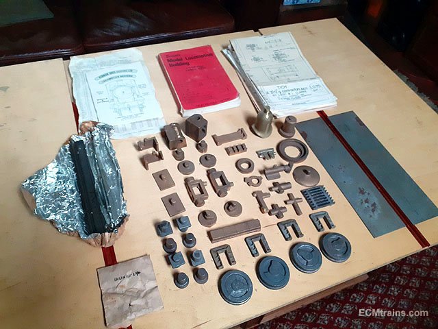
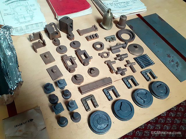
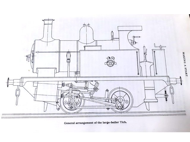
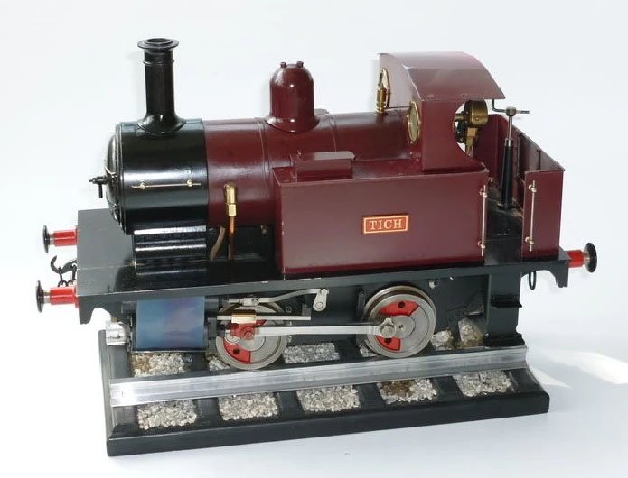
A very nice man has donated this kit of castings to the cause...... It includes a full set of castings in gunmetal & cast iron, full set of 11 drawings, frame steel plates, steel angle buffer beams, and LBSC's book on building the loco. The loco was designed by LBSC ( Curly Lawrence ) based on a contractor's shunting tank locomotive. This is his 3.5'' gauge version, running on coal with a boiler pressure of 70 to 80 lb. The loco is heavy enough to pull one person relatively easy. Boiler, body and general stock materials are not included. This project will be stashed away until current projects are complete......... Eoin.
- 1 reply
-
- 4
-
-
until
-
The November Fair Date:-
-
until