.png.c363cdf5c3fb7955cd92a55eb6dbbae0.png)

Horsetan
-
Posts
2,754 -
Joined
-
Last visited
-
Days Won
4
Content Type
Profiles
Forums
Events
Gallery
Blogs
Everything posted by Horsetan
-
Cost of living crisis? What cost of living crisis?
-
Probably just as well. She made ignorance fashionable.
-
Please don't tell me it's Jade Goody
-
Sir David Attenborough?
-
Be careful what you wish for. Meanwhile, I still add tetraethyl lead to the petrol for the oul Citroën.
-
To be fair, they are probably the same as building any lattice post signal, e.g., LSWR, CR, LNER, etc., so go carefully with the soldering iron and use the minimum amount of solder that you can get away with. Those 5ft arms are seriously long, though....
-
The thing that strikes me about the CB&P engines is the triangular, almost minimal, buffer beam...
-
Thing is, could the non push-pull 201s have been upgraded to push-pull? And, if that were possible, is there actually enough work for them to do?
-
Thanks to @KMCE, I now have a clear set of his drawings plus quite a lot of measurements; I now know that the lateral centreline of the inside cylinder is just 4ft in front of the centreline for the outside ones. This shows that the front of the outside cylinders does coincide with the rear of the inside one, and would have made quite a strong rigid structure on the real thing with virtually no flexing in the frames in this area.
-
 Could have been worse. Could have been the Provisional Lion, or Continuity Lion....
 -
Ernies Massive Irish 1930's to 2005 Photo Archive
Horsetan replied to Glenderg's topic in Photos & Videos of the Prototype
Is that 63? That engine looks very S/S2 class to me, and there's a trace of a nameplate on the leading splasher. Looking at the shape of the cabside numerals, I'd say that's a "1" in front. The second numeral is rounded, which I guess to be a "9", and so is the third numeral. That makes the engine S2, either 190 or 192. I'd say it's more 192, so Slievenamon. I know the UTA renumbered this one 63 in its list, but the cabside (and indeed the whole engine) suggests this hadn't been repainted at the time of the photo. -
This is the same question I'm asking. All of the worked examples concentrate on the driving wheelbase only and don't take the bogie into account
-
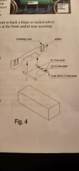
From the album: SSM GSR 800 / CIE B1a 4-6-0 etches
-

From the album: SSM GSR 800 / CIE B1a 4-6-0 etches
Pivot measurements for continuous sprung beam -
On the fifth read-through of the instructions, one of the particular design points stands out: - The kit bogie is designed to pivot from a direct link at the rear to a mainframe stretcher. There are no provisions made for a central bogie pivot, or for the bogie frames to directly bear the weight of the mainframe. This is slightly different to the real thing, where the bogie frames and stretcher directly take the weight of the engine frames and only slide laterally to a limited extent, whilst the bogie axles themselves are allowed to rise and fall. - I want to see if the kit bogie can be modified to act more like the real thing. That means trying to make room for a central pivot / slide, not a rear one. Helpfully, the kit has an "L"-shaped mainframe stretcher here which is in virtually the right place for mounting a centre pivot. The vertical part of that "L" could also double as the back end of the inside cylinder. I messed about with a spreadsheet initial diagram for the continuous sprung beam (CSB). It is quite rough at the moment: This is based on a model weight of 200 grams (I'm sure the completed engine tops out at a good bit more than that), with an estimated centre of gravity ahead of the front axle. With the known wheelbase of 29mm x 34mm , the CSB has provisional pivots / fulcrums set at 16mm ahead of the centre driving axle and 19.5mm behind it. The outer anchors are set at 14.5mm ahead of the leading axle, and 11mm behind it. The spreadsheet which works all of this out calculates a theoretical weight distribution of 32.5% for front and middle axles, and 35% on the rear. The aim is to get each axle bearing 33.3% each, so the current working is just messing with settings. Incidentally, anyone interested in messing with CSB suspension might find the spreadsheet tools useful.
-
Can-kicking is cheaper
-
I'm not sure if I had a sense of surreality or absurdity as I read that. Maybe both....
-
Anything that sheds a bit of light is welcome
-
300 quid is etched brass and n/s superkit territory anyway. I think there's a lot of us in the hobby who feel entitled to have top-notch models at rock-bottom prices - that's how the Internet has conditioned us to think. It's an extension of the oul something-for-nothing. In a weird way, if you go back to the days when real railways were still being built, people wanted new lines....but didn't want to pay for them either. The more it changes, the more it stays the same.
-
OK so, we're back in Urie N15 wheel territory again.
-
Food waste is such a terrible thing.
-
Interesting. Can the 6'3" diameter be verified? The only sources I have are Steam Index and the Clements & McMahon book, both of which state driver diameter was 6'7". Also, if you look at a broadside photo of a B1a and run a ruler through the driving axle centres and forward, does the line set by the ruler touch the top of the bogie wheels? At 6'3", the radius / midpoint is 3'1½", which would almost touch the top of the bogie wheel tyre. At 6'7", mid point is 3'3½", which would show a gap.... See also @KMCE's section drawing: I'd say the axle midpoint line sails way above the top of the bogie wheel tyre....so 6'7", I think.
-
The coupled wheelbase comes out as 7'3" x 8'6" (29mm x 34mm in 4mm scale)
-
Not only webbed spokes, but also crankpin between the spoke. This one is for 21mm gauge, not OO. The only contact I have with 16.5 these days is in HO. The Scalefour Society's annual Scaleforum show is on at the end of September; the Alan Gibson trade stand usually attends, so there'll be a chance to compare the King Arthur and T9 wheels for suitability. Likewise 247 Developments will be there and hopefully will have a stock of the nameplates. At this rate, I might have to build some 21mm test track.....
-
I think the rule is that the key leads the direction of travel, so it's inserted ahead of the chair for forward movement; as the engine moves, it effectively claws the rail and key back into the chair.