Tullygrainey
-
Posts
952 -
Joined
-
Last visited
-
Days Won
56
Content Type
Profiles
Forums
Events
Gallery
Blogs
Store
Community Map
Everything posted by Tullygrainey
-
Workbench is certainly looks busy but what's the point of having tools if you don't use them Glad to hear you've made progress with the Barclay David. It will have been worth the effort. It always seems to be the case with loco building that, even though you try to make painting it the very last part of the process, something always conspires to upset that plan and the paintbrushes have to come out again! However, I always feel that getting the thing running properly is 9/10ths of the task. Once that's achieved, the cosmetics can be tackled with enthusiasm Onward and upward.
-
Bogies!! (grunts, spits in gutter). A pain in the proverbial. You have my sympathies David. Looking at your pics, a few things occur: Does the bogie have enough lateral movement? Would a bit more help lessen that sharp angle with the drivers as the loco enters curves? Are the springs that control lateral movement too strong and are they actually preventing sideways movement? Have you tried running it without the springs? I used the Ahern curved slot approach on the bogie for my BCDR 0-6-4 tank. The width of the slot is the only restraint on bogie movement - there are no other wires or springs and the bogie is left to do its own thing. It clatters happily through Peco OO short points and I haven't had any problems with derailing. It's full of lead which also probably helps keep it where it's supposed to be. In the past, I've noticed that leading bogies without the ability to move sideways often start to tilt instead when they enter a curve. The inside wheels lift off the track and the bogie eventually jump the rails or causes the drivers to derail. It's what prompted me to use a slot. Good luck with the debugging. Alan

-

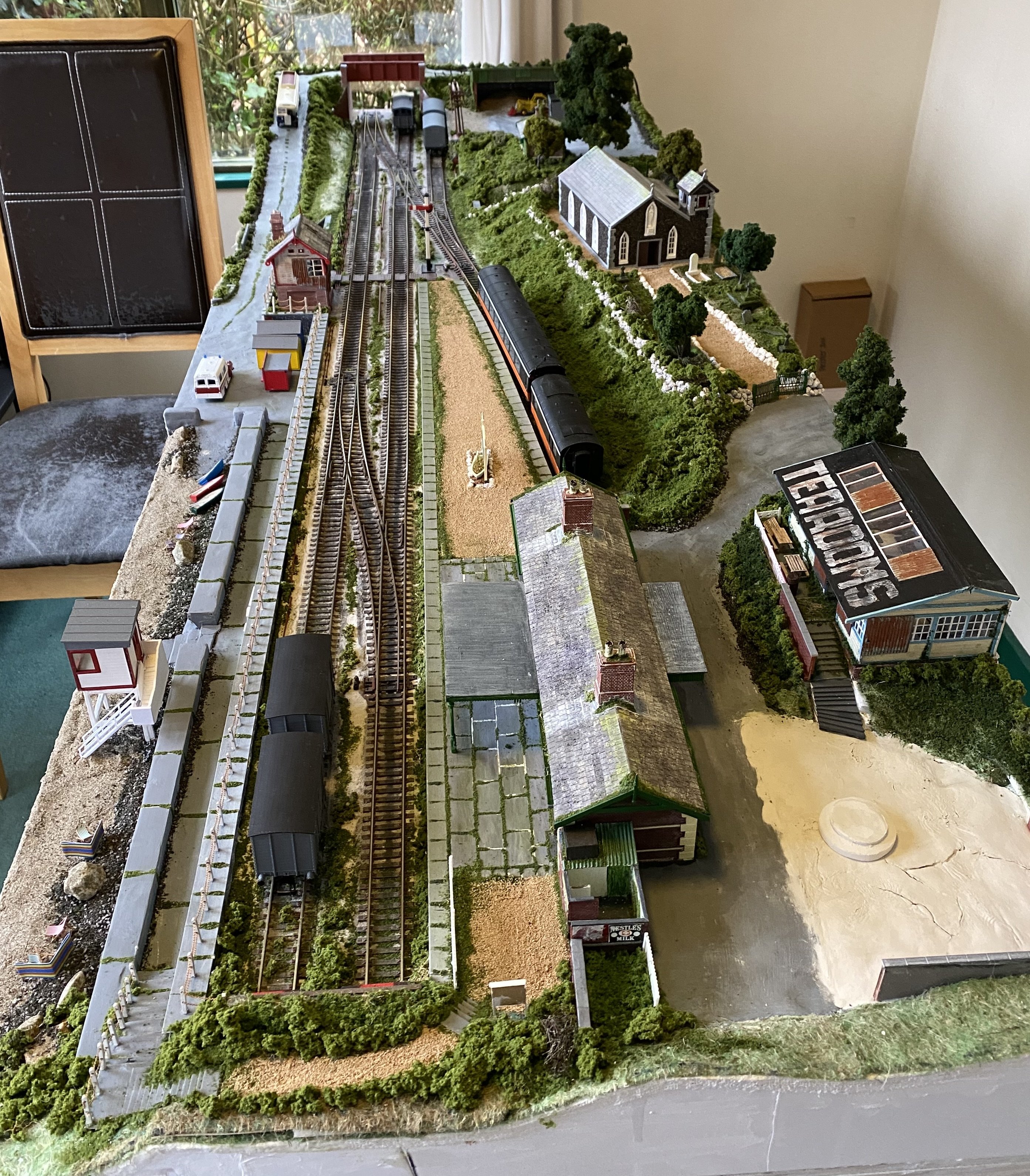
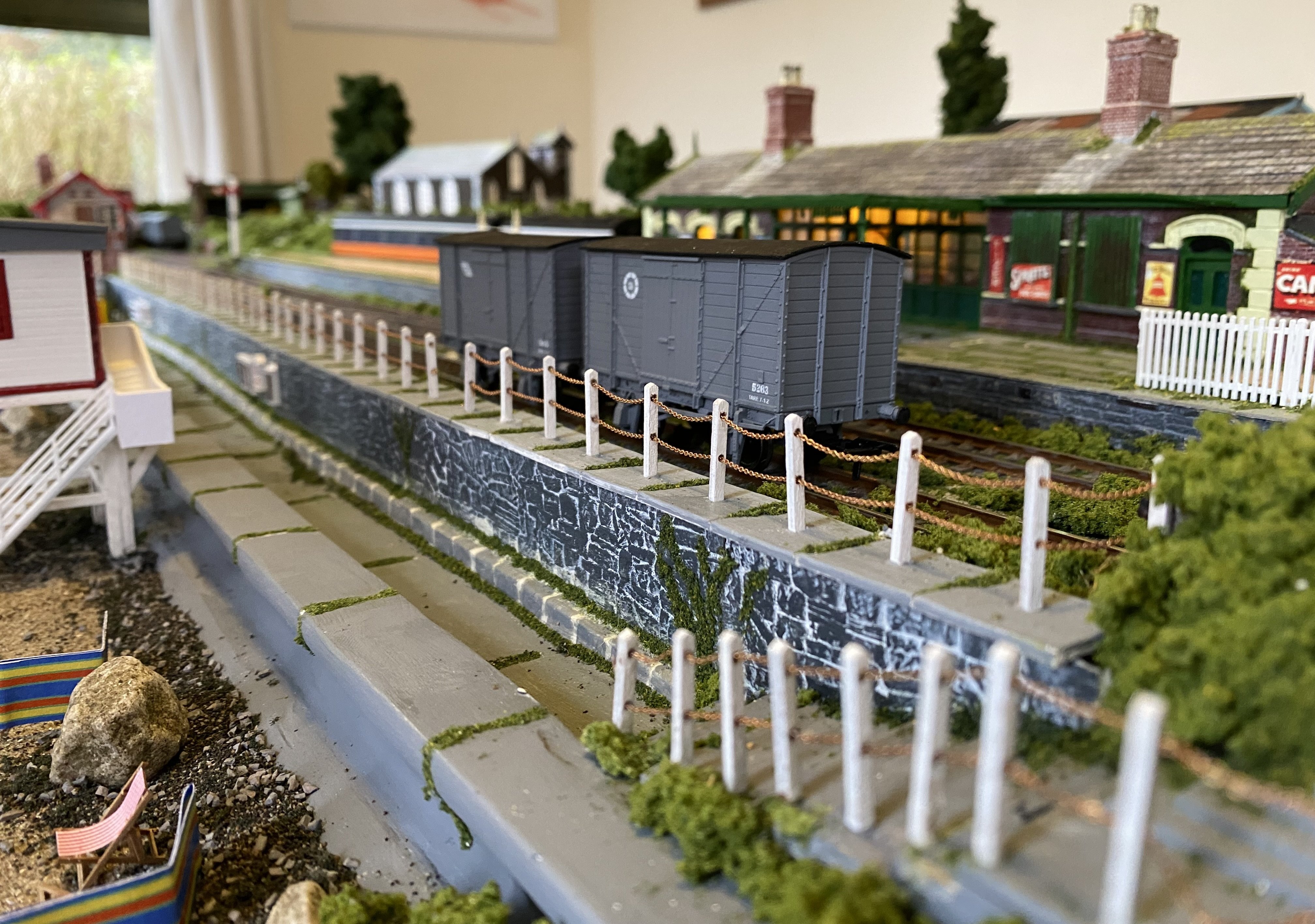
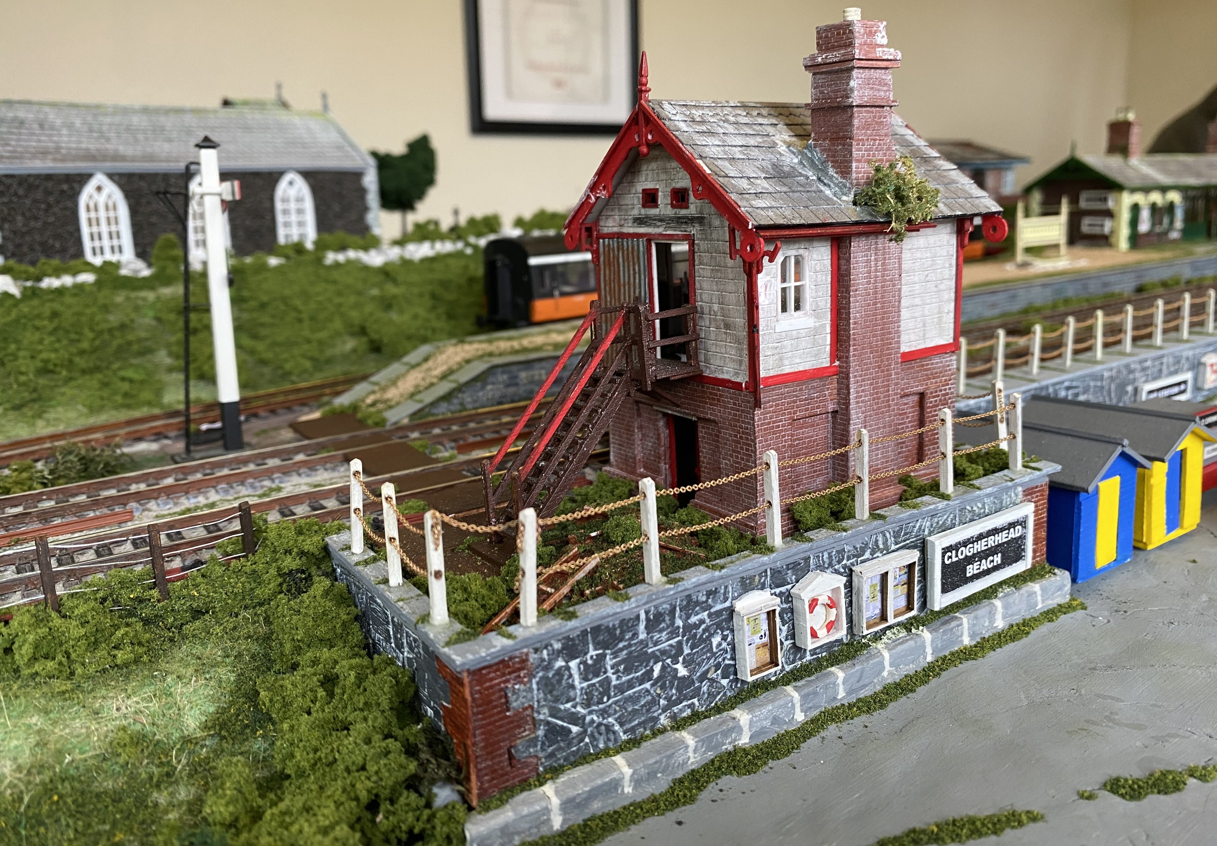
Clogherhead - A GNR(I) Seaside Terminus
Tullygrainey replied to Patrick Davey's topic in Irish Model Layouts
Leslie will correct me if I'm wrong but they look like Railtec transfers. I've checked the Railtec site and they offer a range of GNR(I) options but nothing in 7mm unfortunately David. Might be worth an email though because they do have other 7mm stuff in their catalogue. -
Wonderful! I love the B&W image. Full of atmosphere and detail but beautifully understated and the oul fella with his hands in his pockets just brings it to life. Less is definitely more here!
-
Clogherhead - A GNR(I) Seaside Terminus
Tullygrainey replied to Patrick Davey's topic in Irish Model Layouts
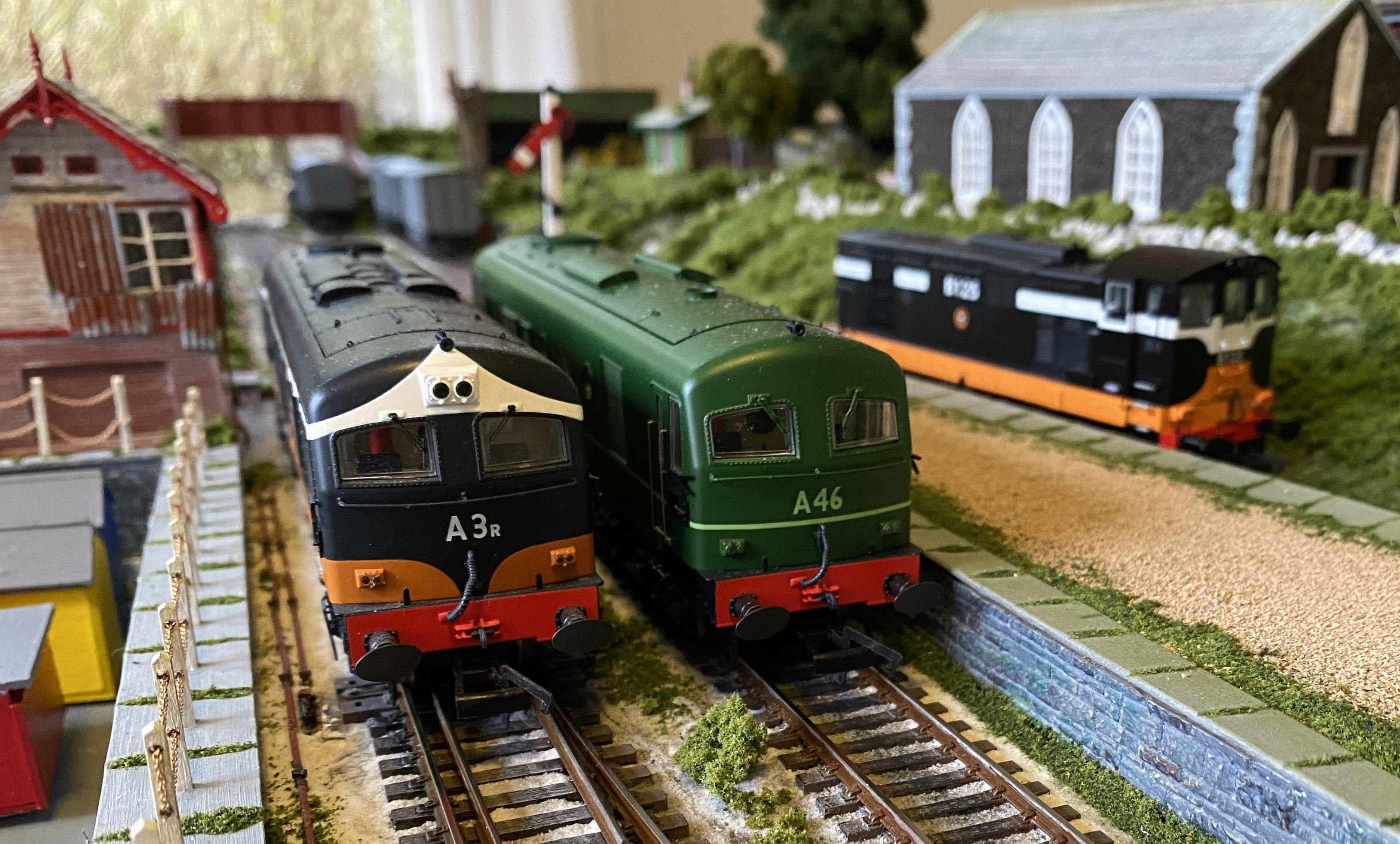
Had a very enjoyable day trip to Clogherhead today. I must say the original station building has weathered well. The dimly lit interior is like being in a time warp. The tearooms were closed (looked like they had been for a while) but we had the foresight to bring a packed lunch and so we just sat in the deckchairs down on the beach, eating our sandwiches and digging our toes into the Clogherhead sand. We'd have hired a dingy for a spell round the bay but there was no sign of Rowan Boats and being the good citizens we are, we wouldn't have taken one without paying. Some interesting motive power came past while we dozed in the weak sunshine. These beasts make a mighty racket when they get together. We were so engrossed in loco spotting, we missed the last train out but there's always a bus. Thanks Patrick. It was a blast. Brilliant layout. A credit to you. Alan
-
Has anyone said ‘a towering achievement’ yet? OK I will.
-
I like this!
-
Quality work!
-
Looks like his dream went up in smoke. It strikes a sad note for sure.
-
Judging by the prototype photograph of 254, the Austin is relying on its handbrake to stay aboard!
-
This is a really worthwhile project Paul. I wish you well with it. Don't suppose you have and Belfast and County Down locos in your collection?
-
N Scale Ballywillan, Co Longford.
Tullygrainey replied to Kevin Sweeney's topic in Irish Model Layouts
This isn’t model making, it’s miniature architecture! Wonderful work Kevin. Really impressive. -
Something out of a Transformers movie?
-
Brilliant stuff Ken. I’ve been drooling over these photos. The 3D prints are wonderfully crisp.
-
Definitely wow! I remember being bowled over the first time I saw pictures of Pempoul. The landscaping was just so good. Best modelling I’d ever seen. I’m sorry I never got to see it for real. They’ve retired it now I think?
-
Lovely stuff David. The rolling stock is looking suitably care-worn. Very convincing. The movement sequence sounds good and would be interesting to do and to watch. That the layout can support movements like these is a fair indication of the thought put in at the layout planning stage.
-
You may have noticed my model of No 18 started out as a full English
-
That's an impressive and very solid start. Puts my woodworking efforts to shame Very best wishes for the project. This one's going to be mighty I think!
-
Had them for breakfast, you might say
-
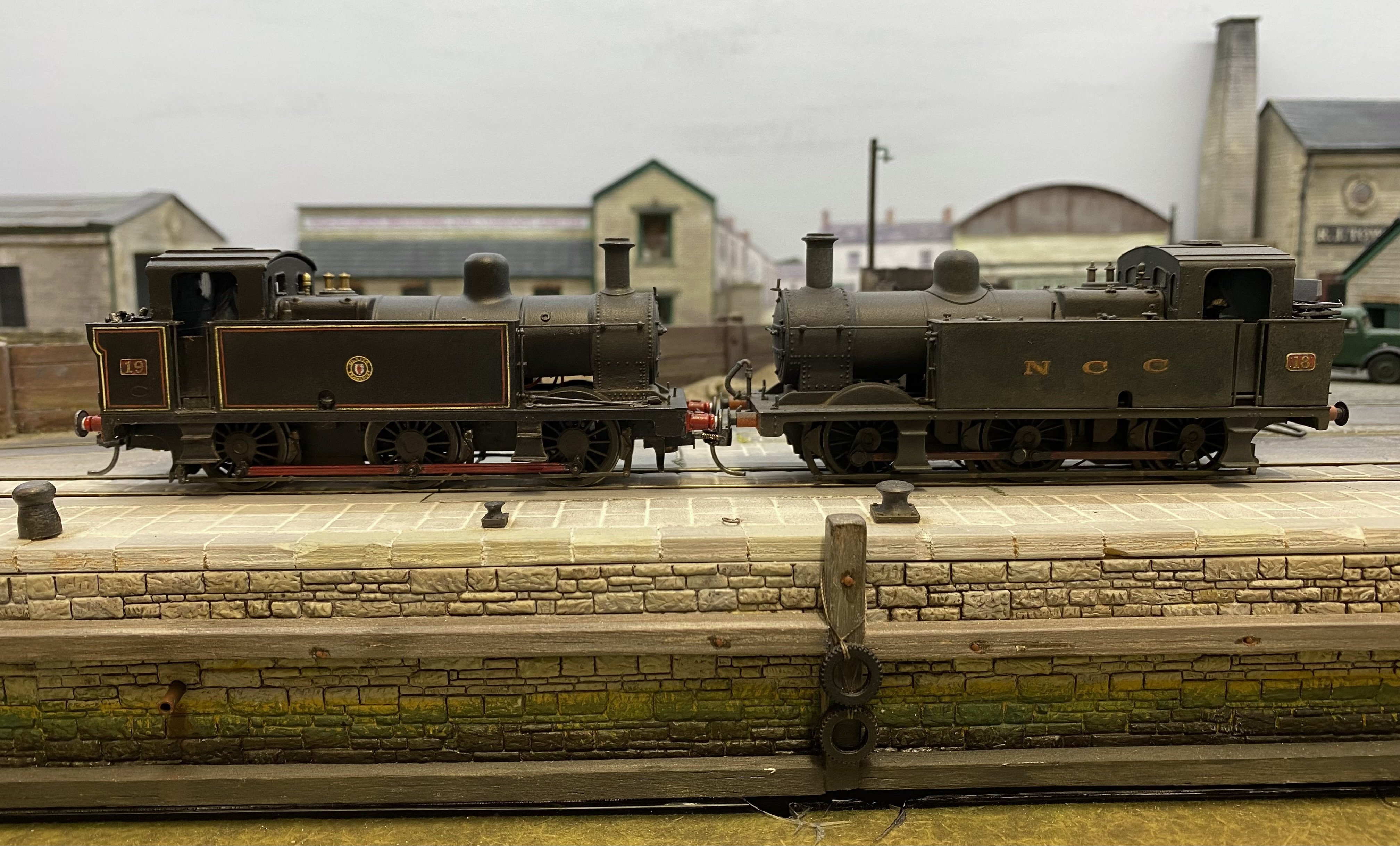
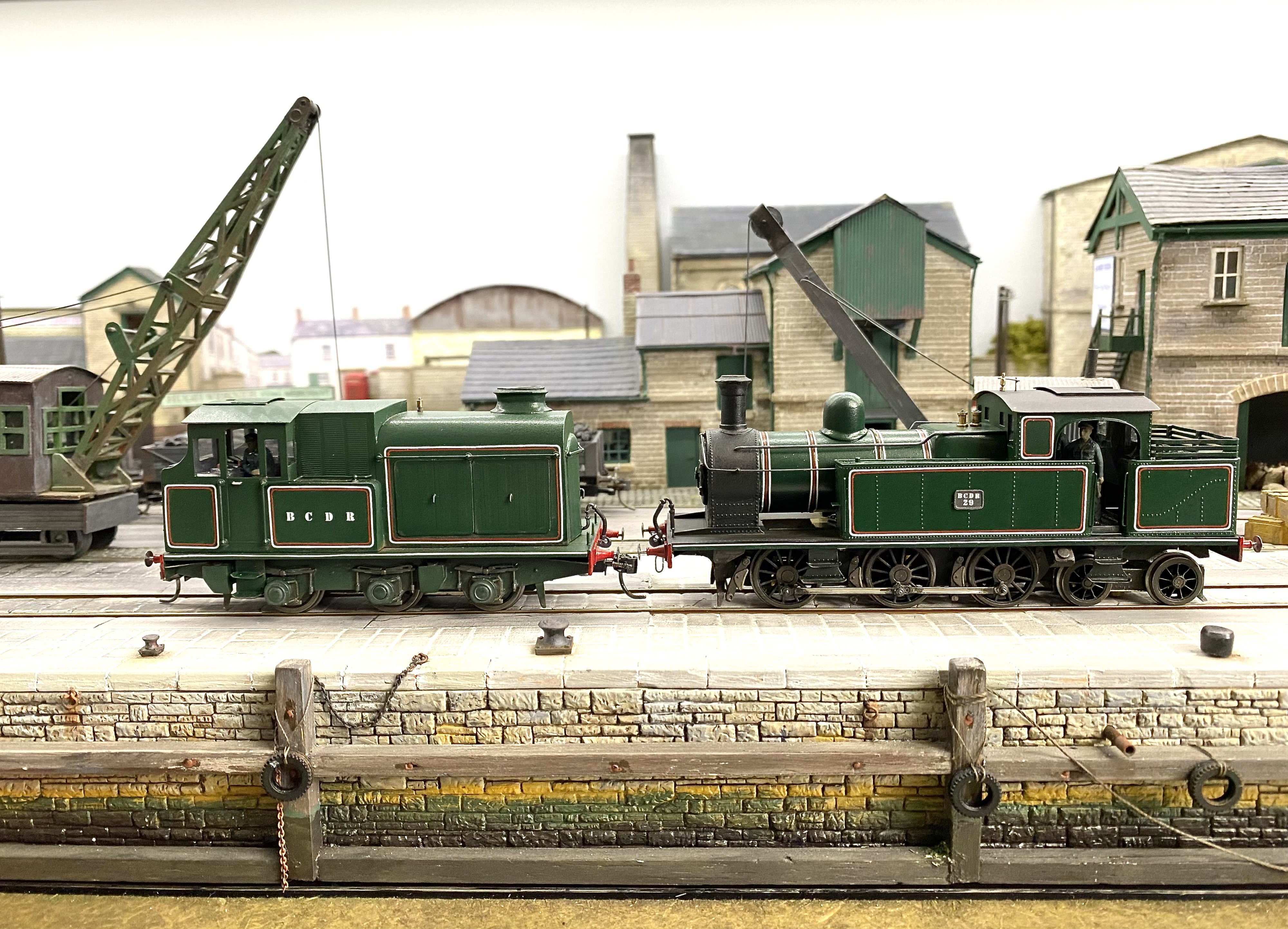
Yes, me too It's a shame one of this pair didn't make it to Witham Street.
-
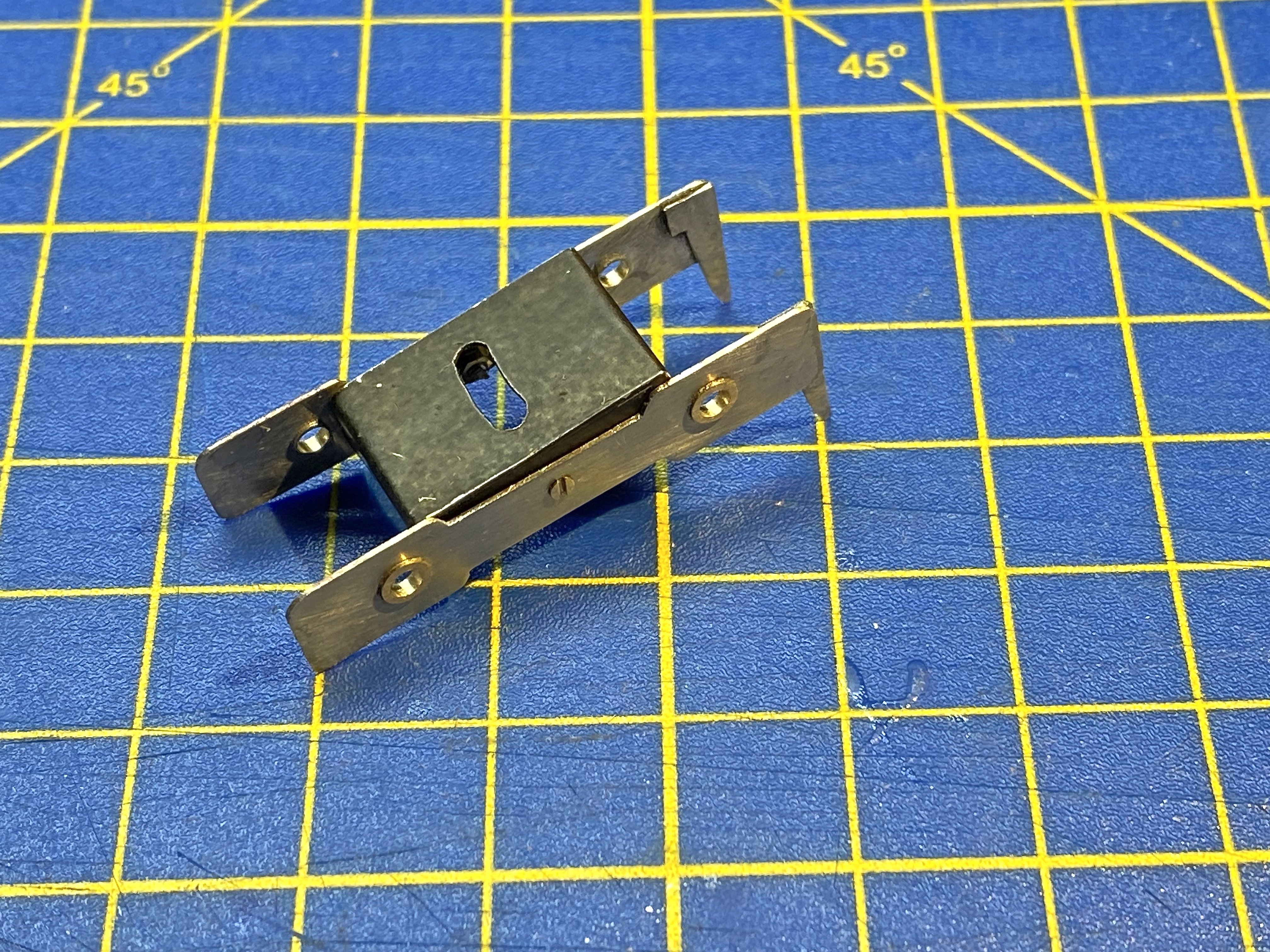
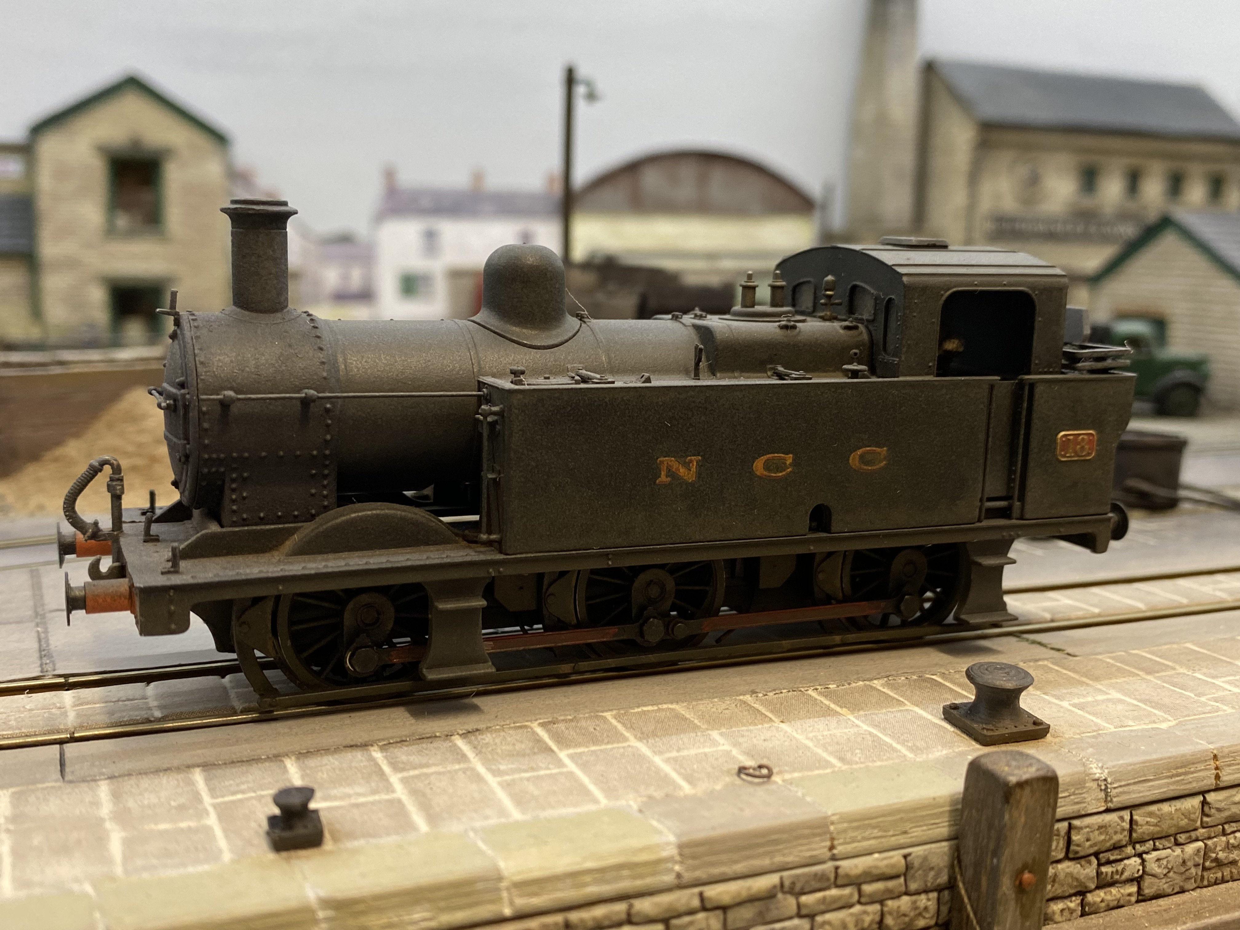
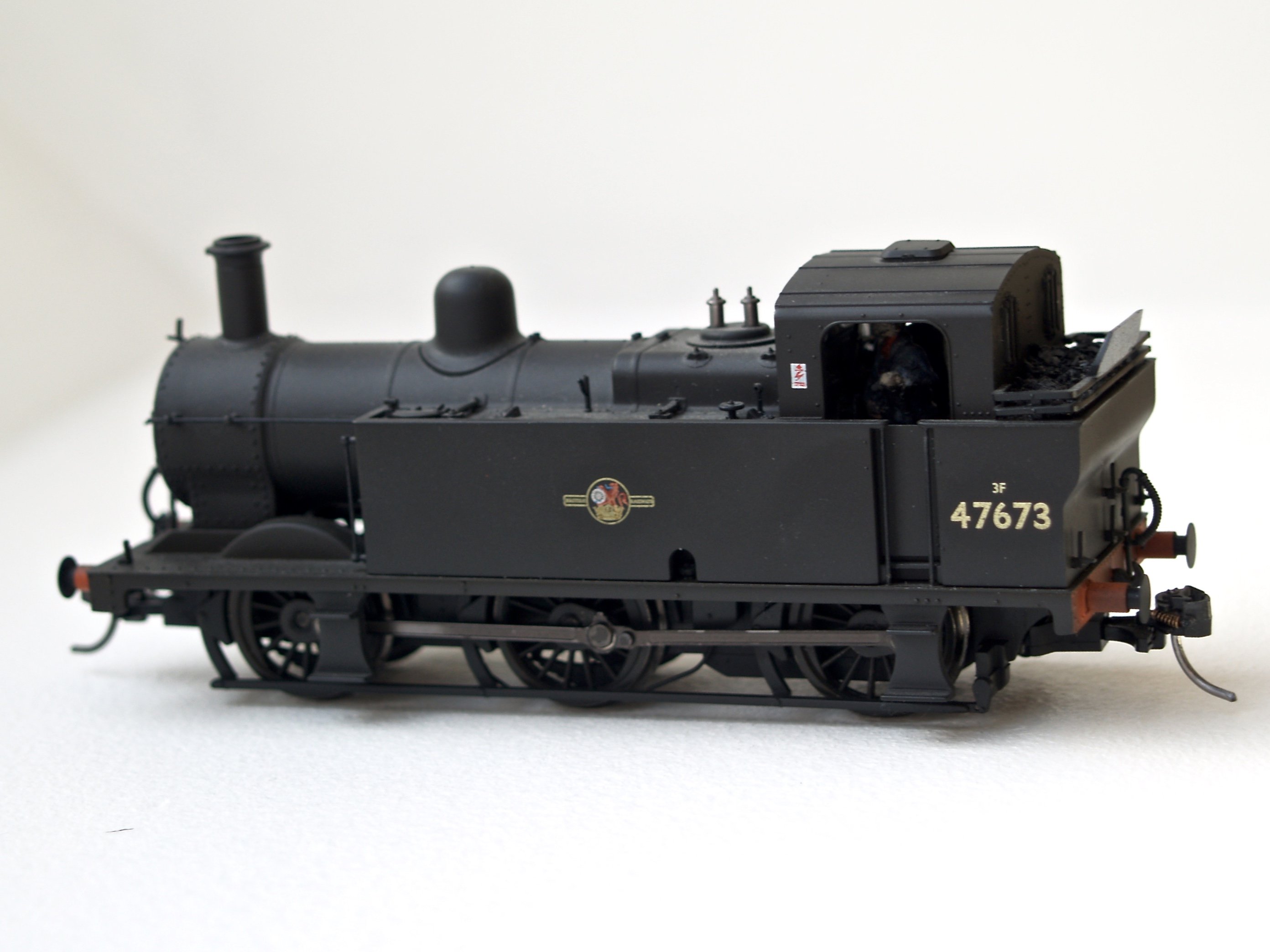
Another Jinty. This one required a good deal less work as it's a bog standard Bachmann Fowler 3F which started out in BR livery and is now masquerading as NCC Y Class no 18. Railtec supplied the livery and Humbrol the grime. I have a photo of the prototype looking even grubbier than this. Before... .. and after. Don't suppose they ever appeared together like this. I assume they both got the livery change at the same time.
-
Imagination and ingenuity - the best tools any modeller can have!
-
Clogherhead - A GNR(I) Seaside Terminus
Tullygrainey replied to Patrick Davey's topic in Irish Model Layouts
What a bright idea. Brilliant! Seriously though, Patrick it looks terrific. Very atmospheric. -
Brookhall Mill - A GNR(I) Micro Layout
Tullygrainey replied to Patrick Davey's topic in Irish Model Layouts
Any more news on the Sherman, Patrick? We seem to have lost track of it. Has it tanked? -
Well spotted! You may have noticed I moved the sweetie shop. No point tempting impressionable engine drivers to spend all their pocket money on clove rock or chocolate toffee rolls.