Tullygrainey
-
Posts
934 -
Joined
-
Last visited
-
Days Won
55
Content Type
Profiles
Forums
Events
Gallery
Blogs
Store
Community Map
Everything posted by Tullygrainey
-
Absolute gem!
-
That is surely a labour of love but it will be worth it. Looks terrific! And totally convincing. I like the small irregularities and the sagging ridge.
-
Nice bit of heavy corrosion on that cab roof
-
That last pic is a charmer! The bridge sits nicely in the landscape and I love the track curving away out of sight
-
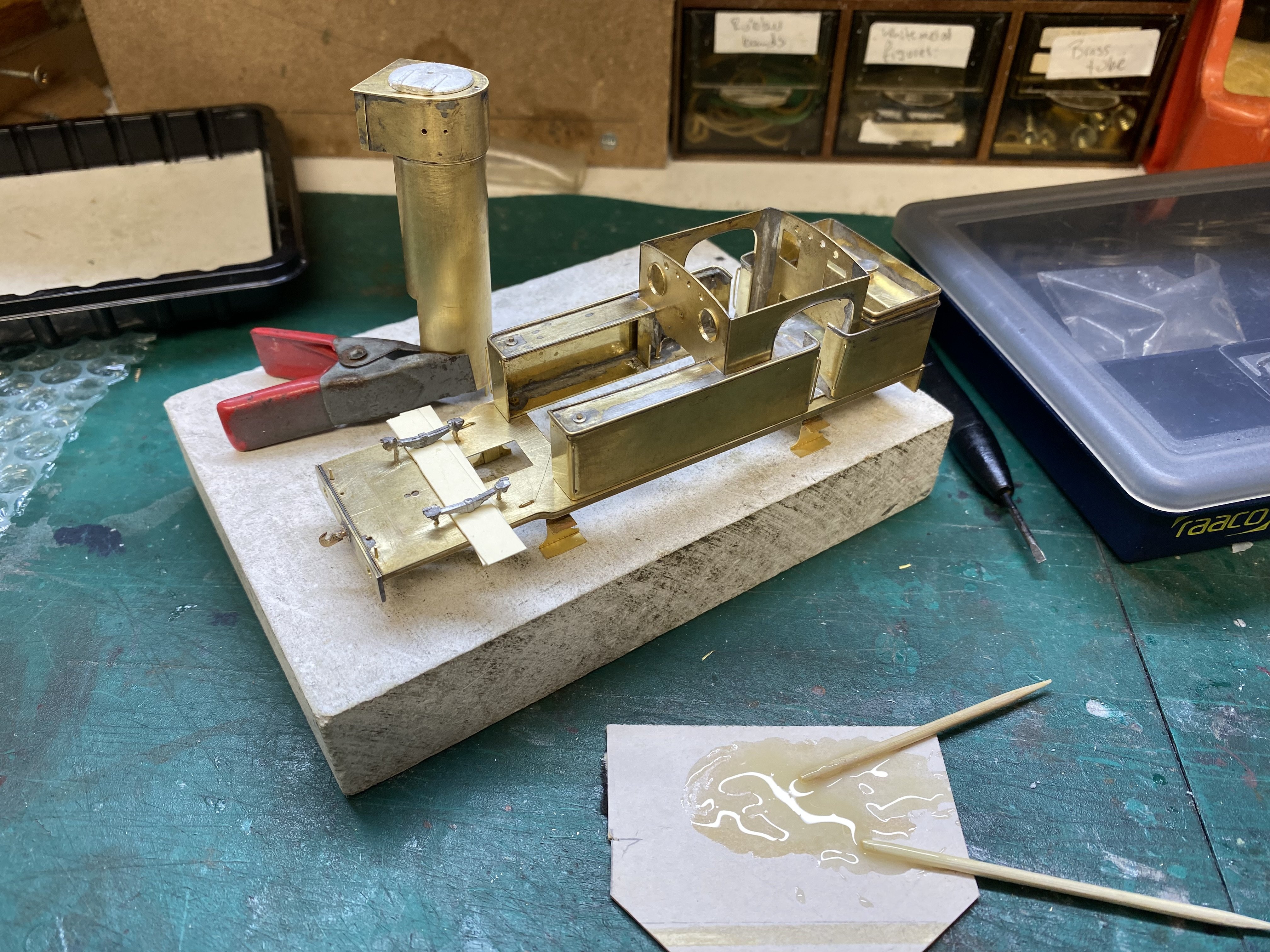
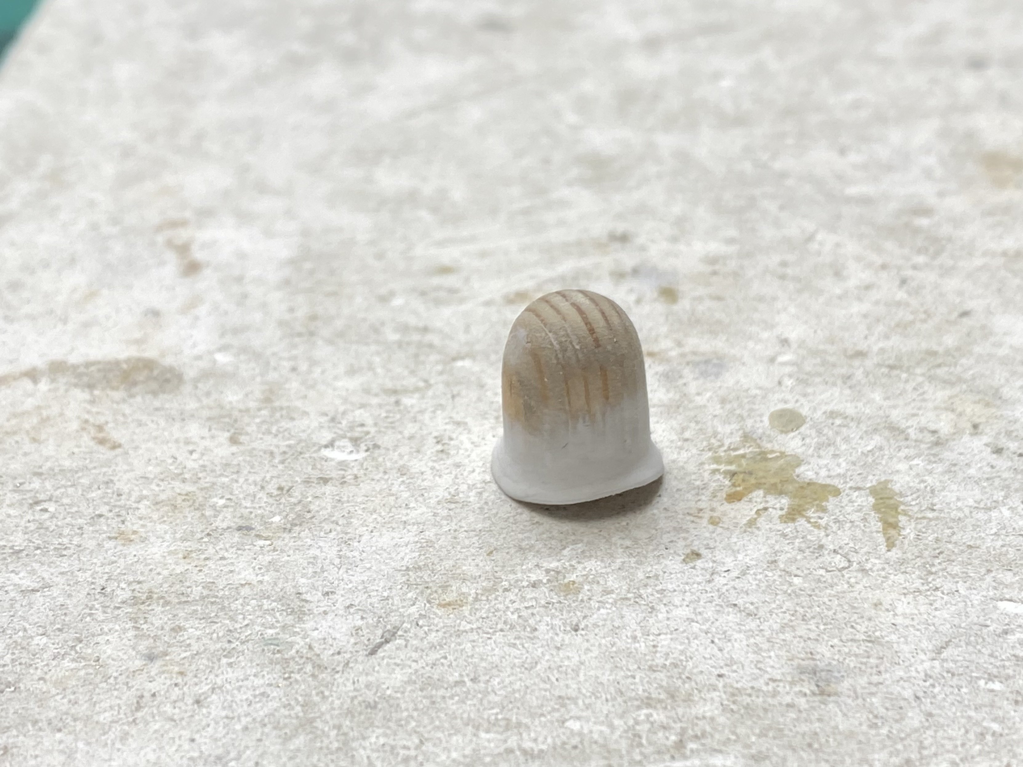
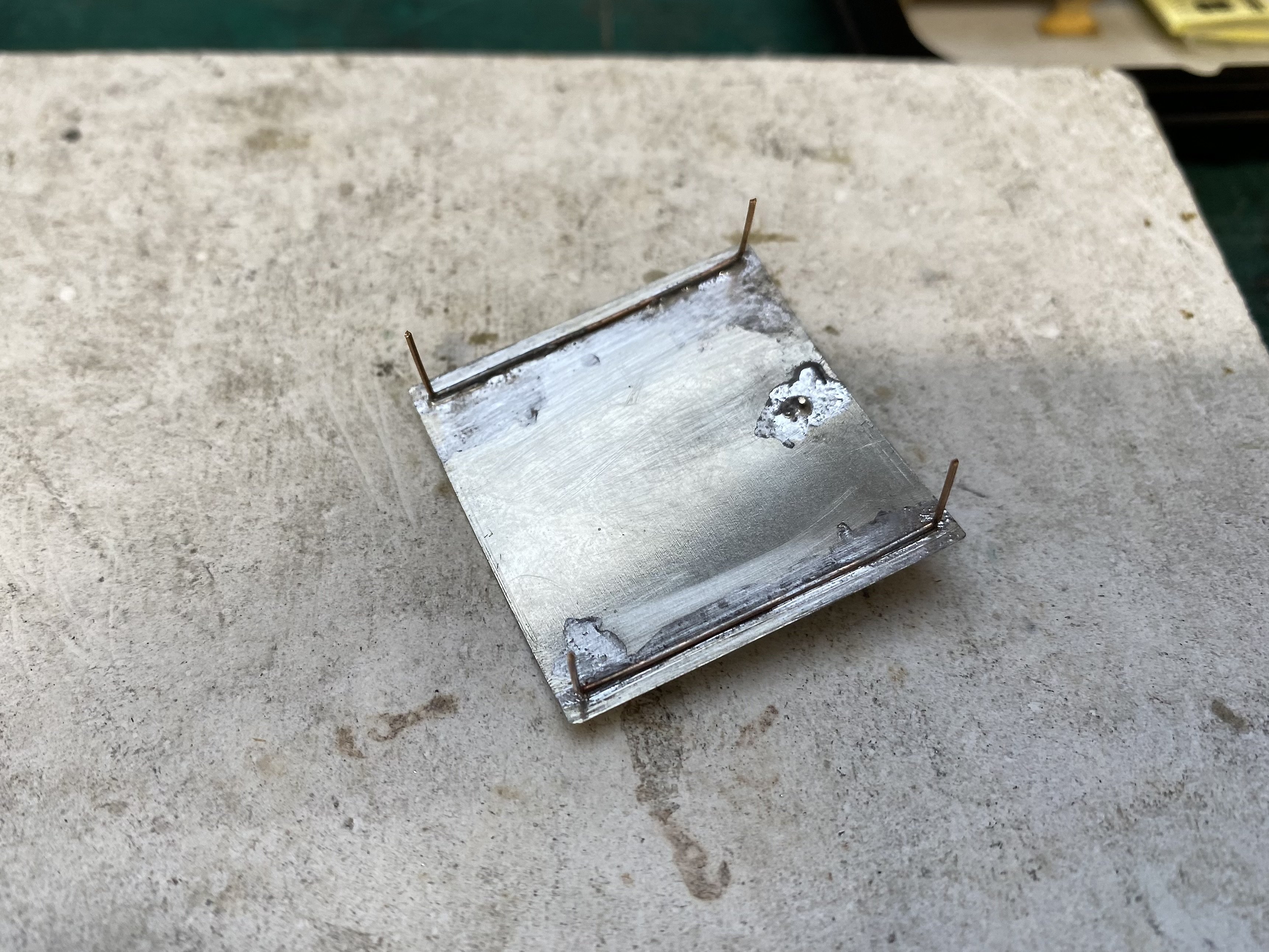
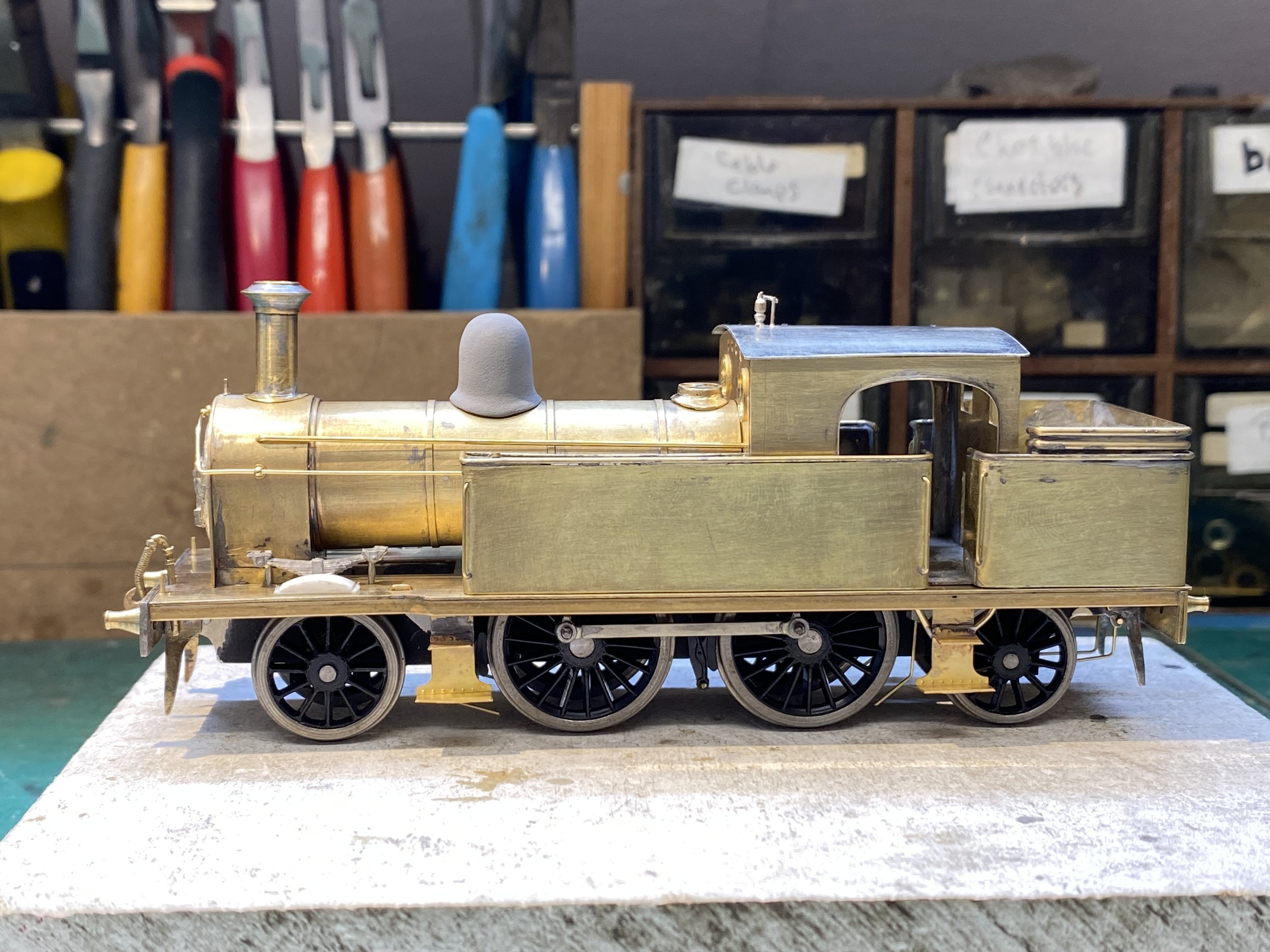
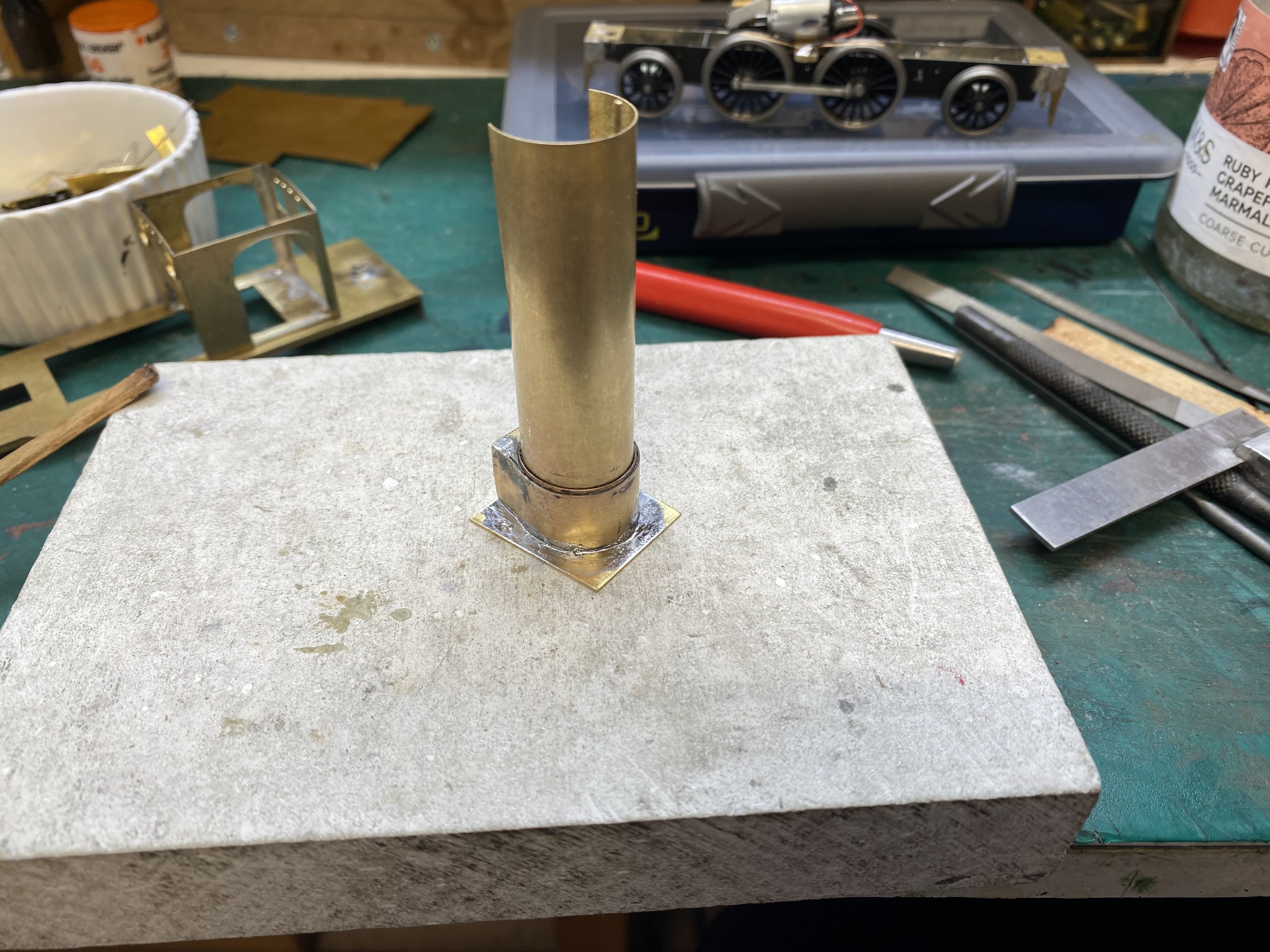
A week spent sweating the small stuff. The chassis got some sandboxes left over from an RT Models kit. Then brake gear with brake pads in plastic to avoid issues with shorting (Alan Gibson 4M103, GWR Tender Brake Gear). Back with the superstructure, some whitemetal wagon springs (MJT 2284) and brass rod epoxied into place made a reasonable representation of the front springs which are visible just ahead of the tanks. The smokebox door is another whitemetal casting (Mainly Trains MT329 from Wizard Models). Chimney was made as before from brass tube, solder and a washer, shaped with files and emery paper in the electric drill. The dome was made the same way but with wooden dowel, plasticard and filler. I usually use a central bolt and captive nut to attach the cab roof but this time I tried this method which I learned from the late Ken McElhinney's (KMCE) workbench thread. The phosphor bronze wire slots down into the cab corners and holds the roof tight. It works a treat. Thank you Ken. The handrails, pipes and sundry cables are variously 0.33, 0.45 and 0.7mm brass rod. Most of the bits are just set on to see how it looks. Don't breathe on it or they'll all fall off. Getting close to the painting stage Alan

- 613 replies
-
- 17
-

-

-
 Bachmann are selling sound equipped versions of their O-16.5 Quarry Hunslets John. I've just taken delivery of one and very good it sounds too! IMG_0334.MOV
 -
I think you'll find that Count Zborowsky was killed at the 1924 Italian Grand Prix at Monza driving for the works Mercedes team in a Mercedes M72/94 single seater with a 1990cc supercharged engine rather than in one of his own aero-engined creations.
-
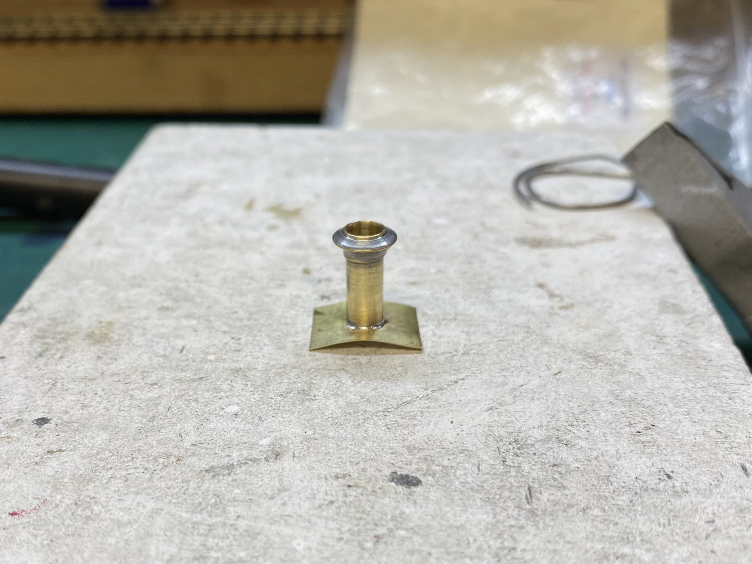
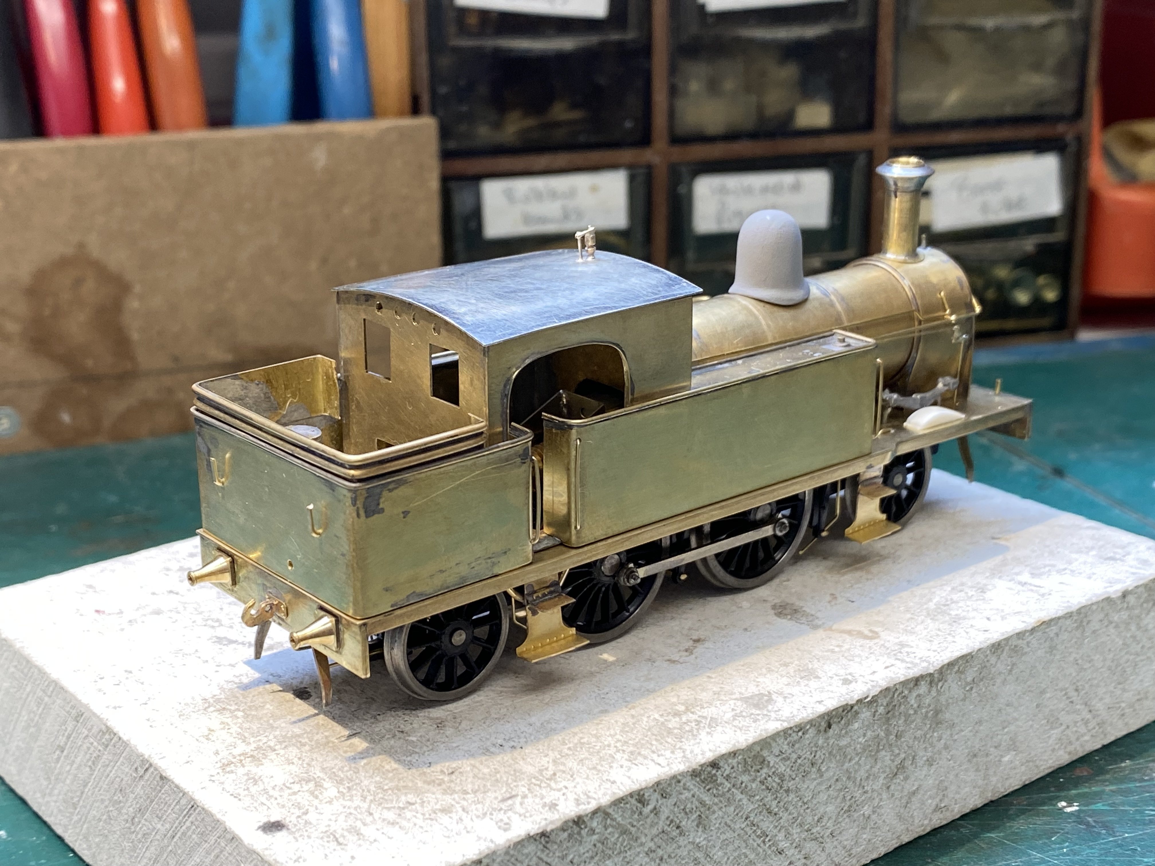
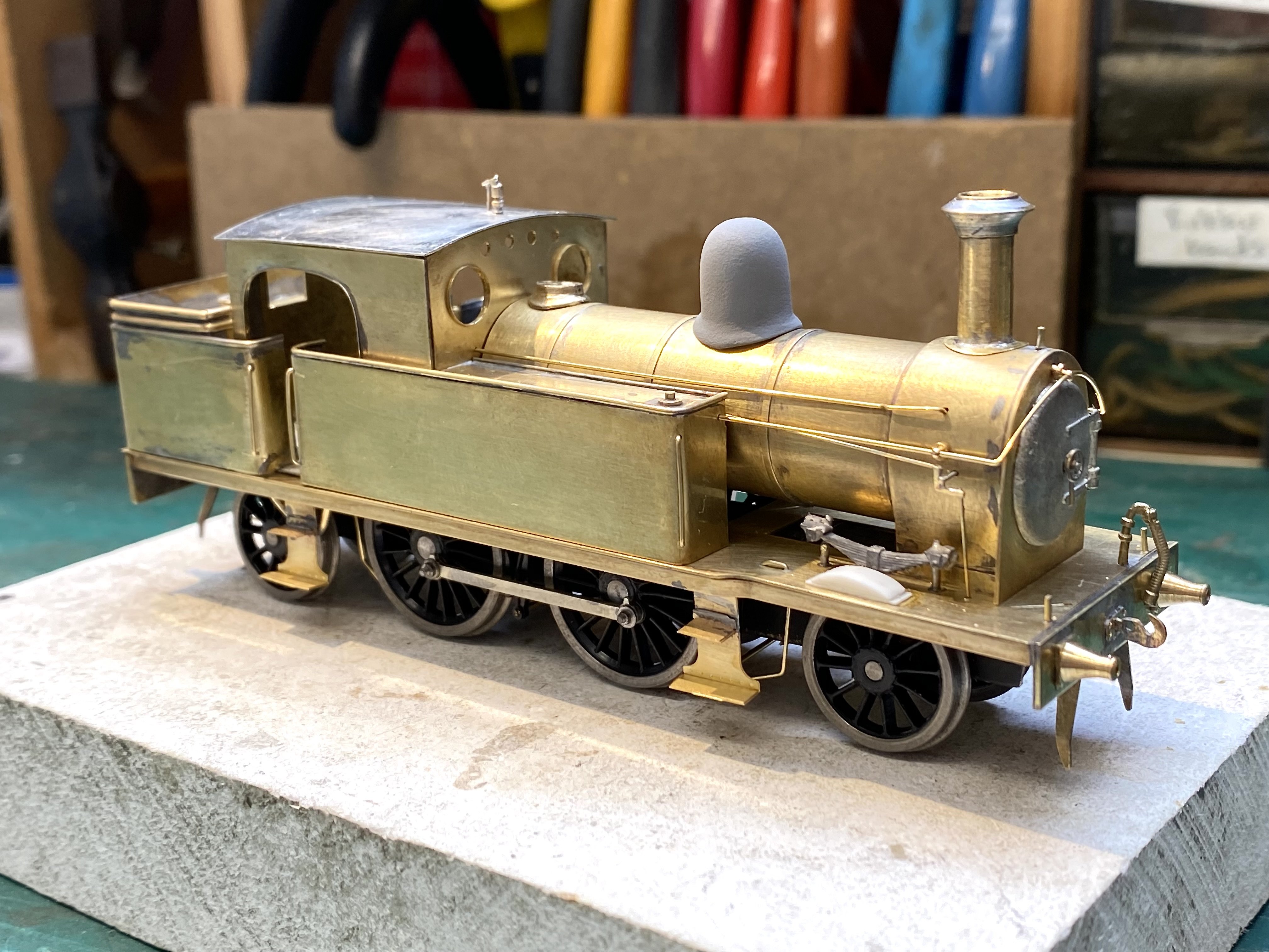
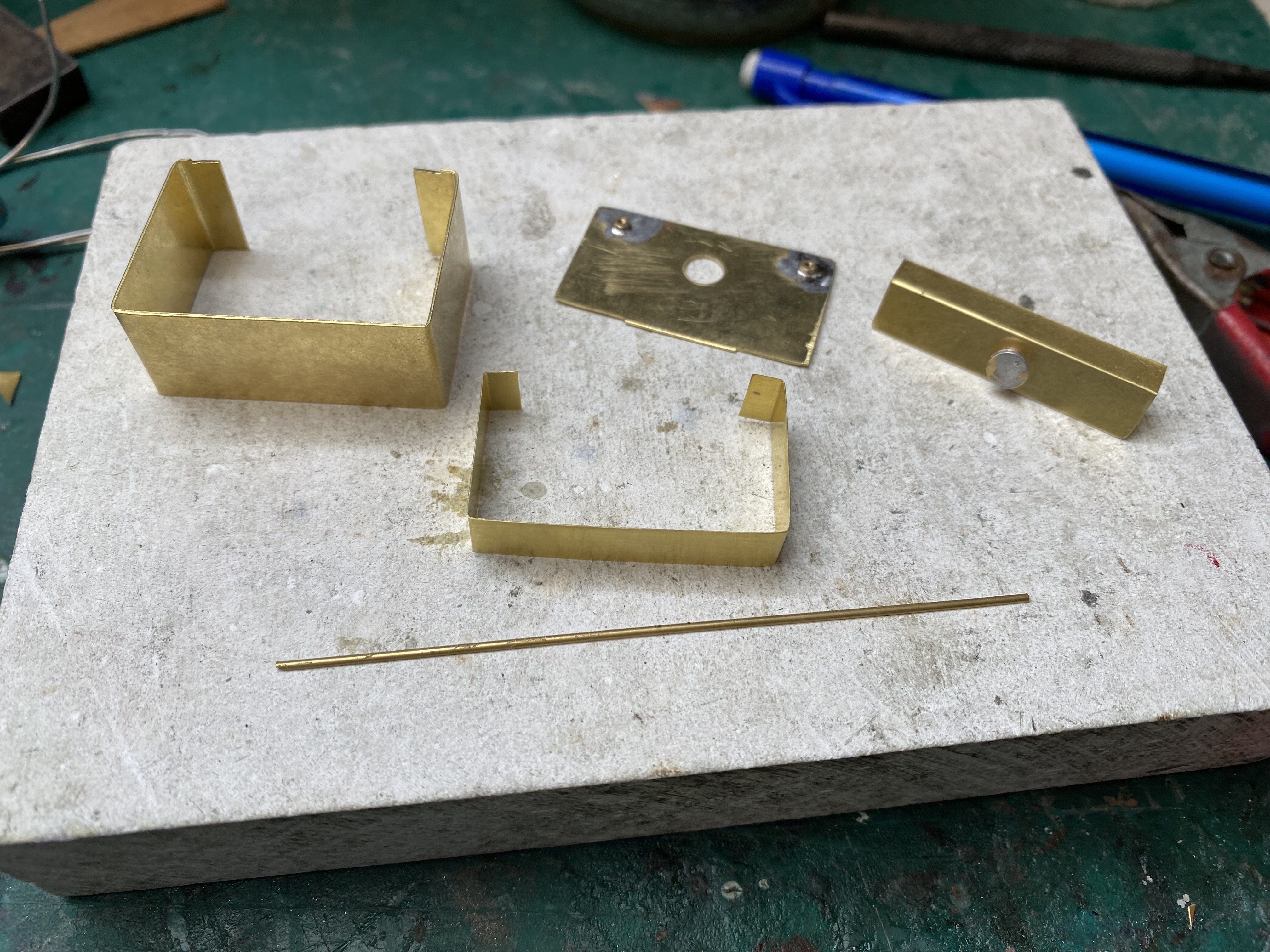
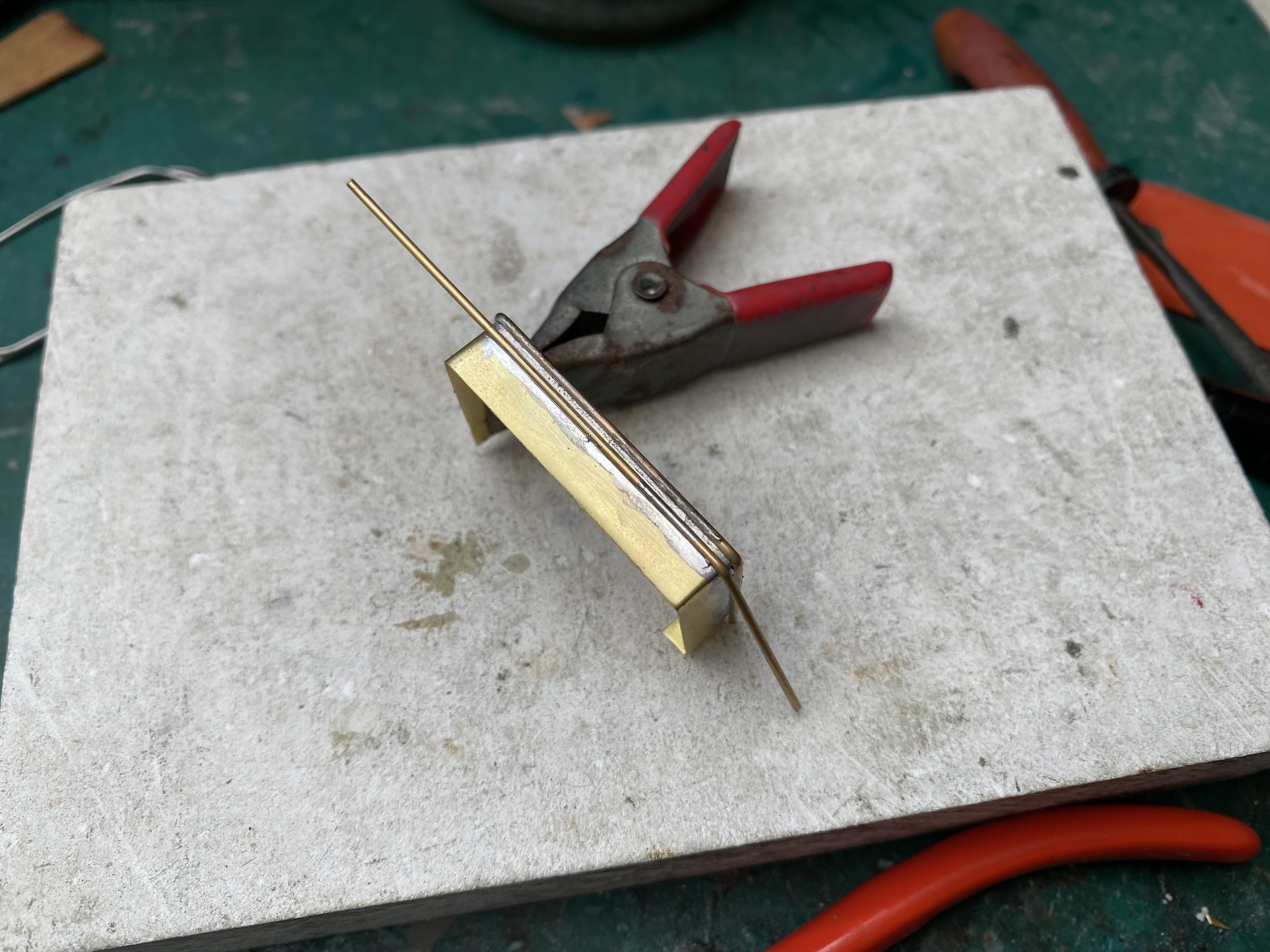
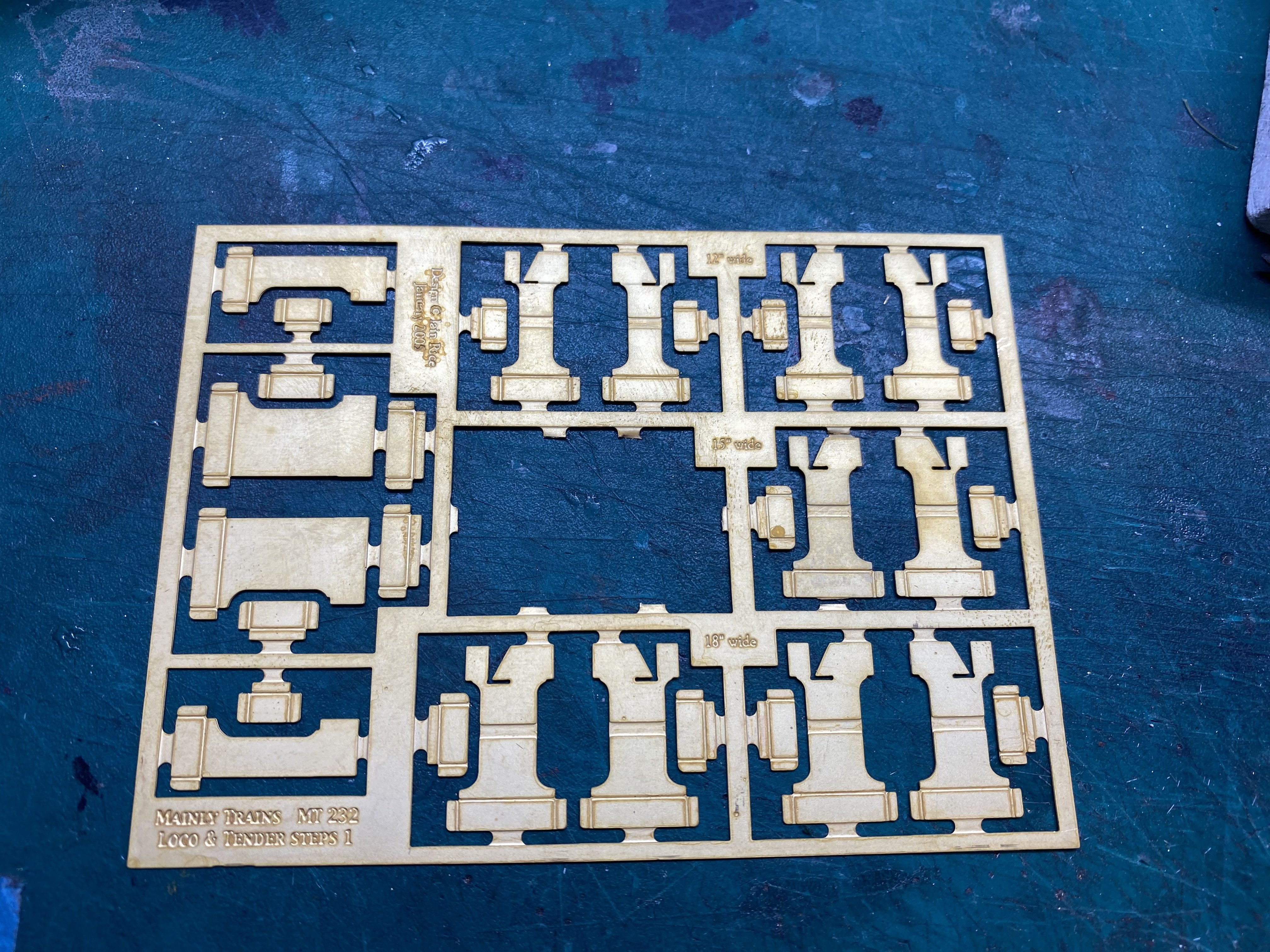
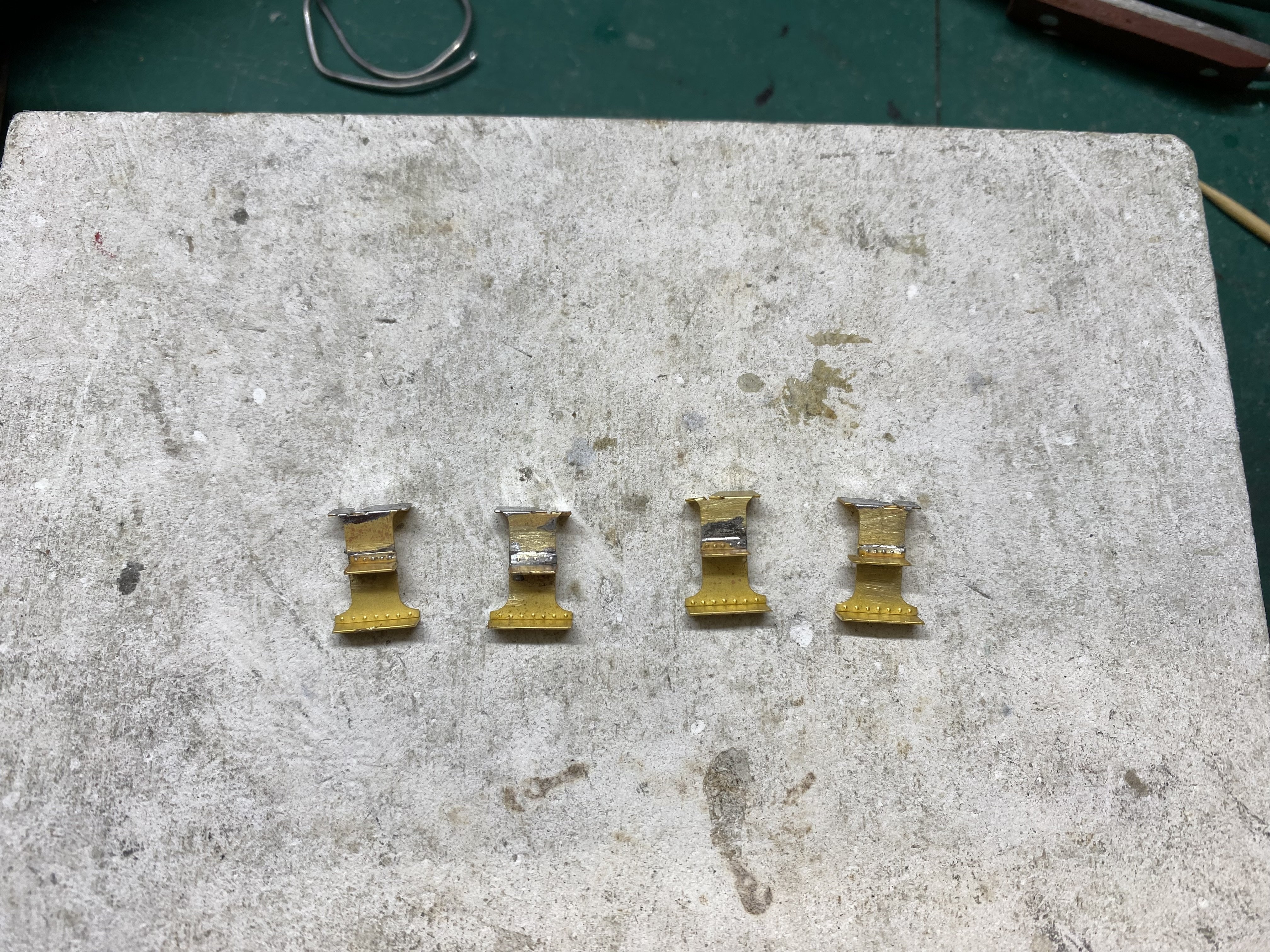
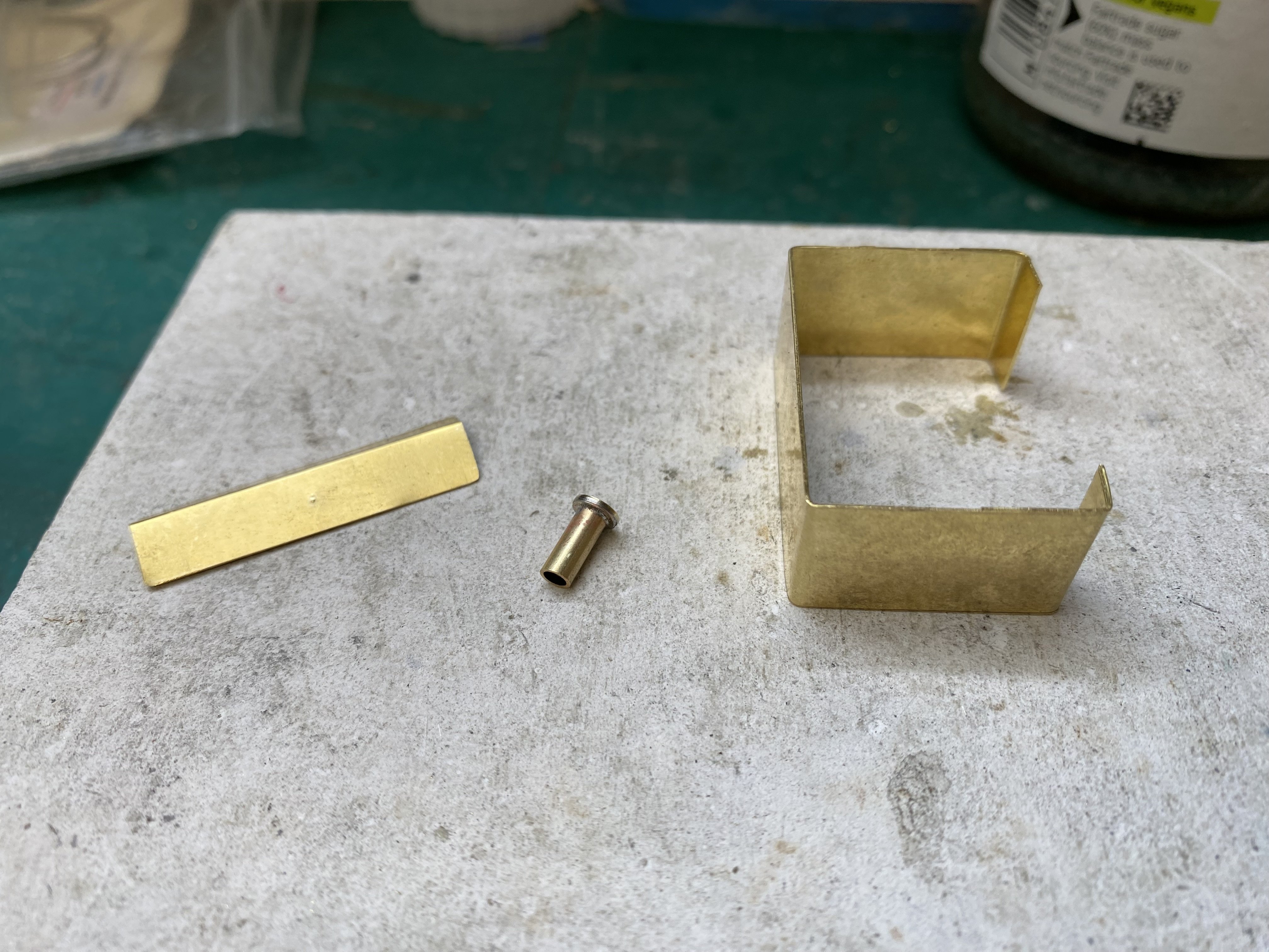
BCDR 2-4-2T got a bunker this week. Bending the outer panel work was a bit hit and miss. I needed two goes to get the width right. It's made in 15 thou brass. Tank filler is brass tube with a conveniently sized washer soldered on. The coal rails on this one have a solid backing with no airspace between individual rails. Made here in 10 thou brass with rails from 1.0x0.5mm half round brass. The bunker has a floor which will be bolted to the running plate like everything else. Having made cab steps from scratch in the past, I was keen to avoid doing THAT again. This fine Mainly Trains etch from Wizard Models had exactly what I needed. What took about 3 or 4 hours before took about 20 minutes this time. Result! I noticed whilst working that it's an Iain Rice design. From some angles, the boiler looks to be going downhill but I've already wrestled with it a number of times and I'm done doing that. Galloping horses and all that. We're getting into the smaller details now. Chimney, dome, smokebox door, buffers, vacuum pipes, safety valves, handrails, whistle, brakes, sand boxes... (continued, page 94). And here's me thinking it was nearly done Alan
- 613 replies
-
- 18
-
-
-
John Gareth Brennan, whose scratch-built models in plastic are amongst the best I've ever seen, tells me that Plastruct TFS 1 is the stuff you need for this job. Good luck with your build. Alan
-
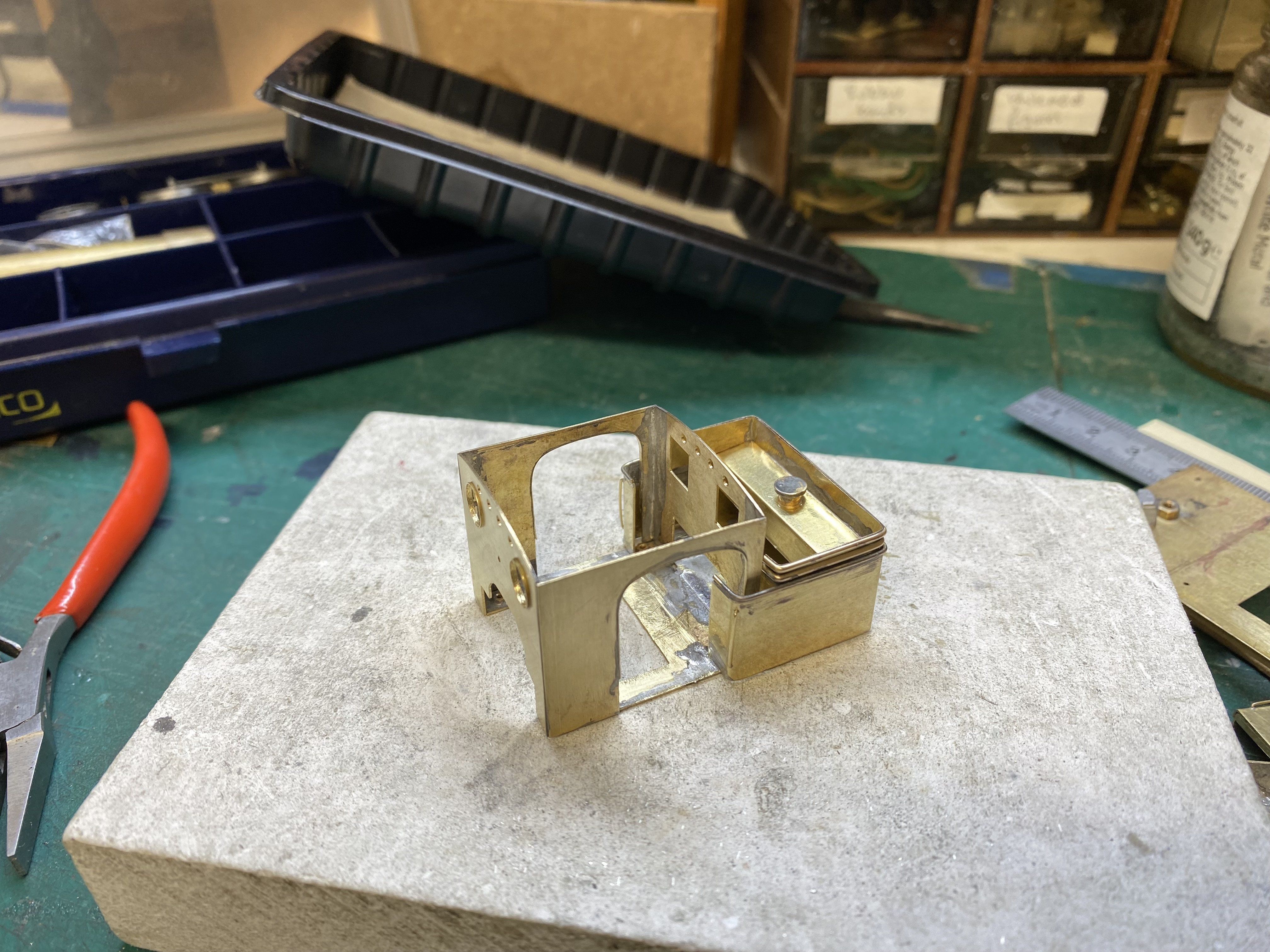
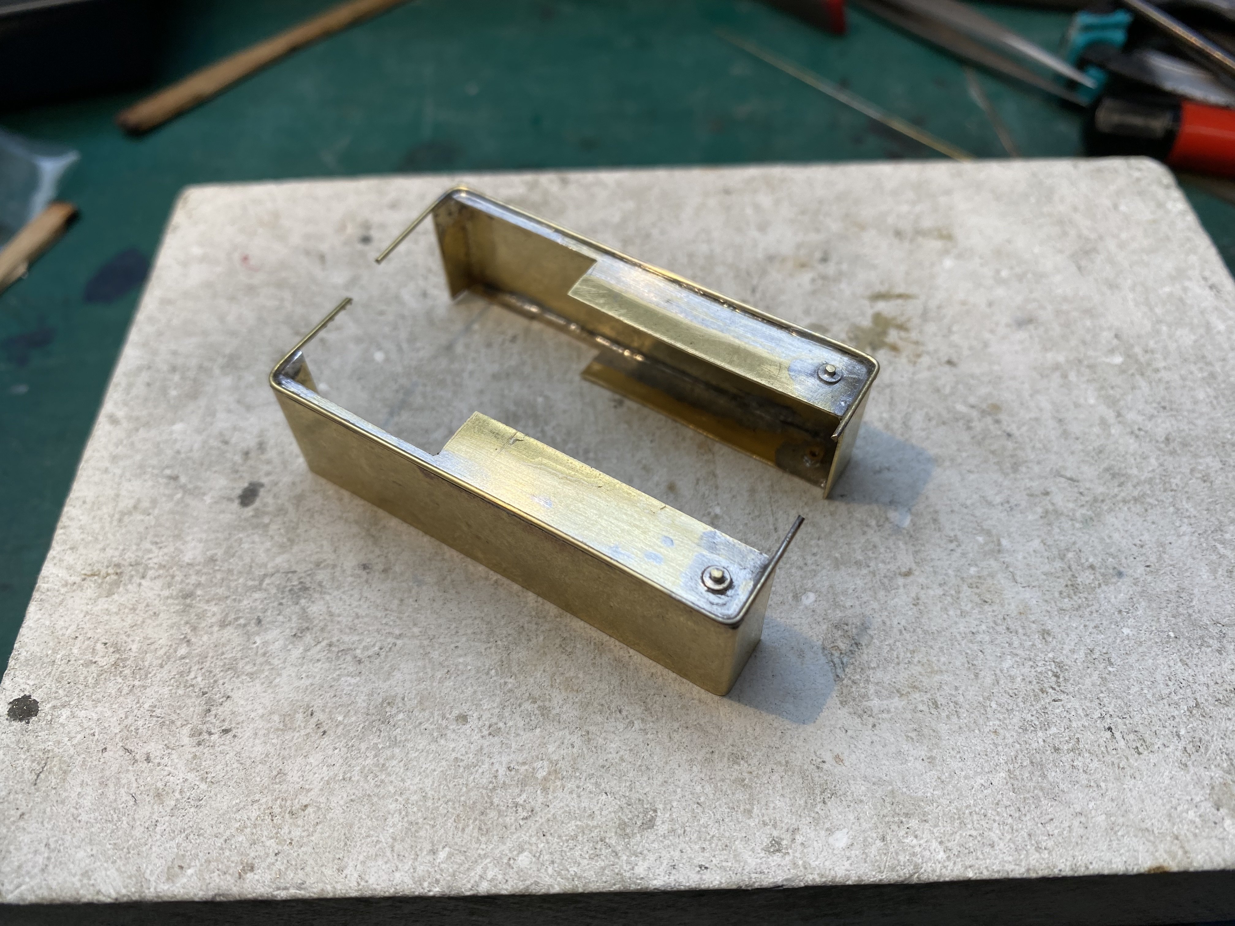
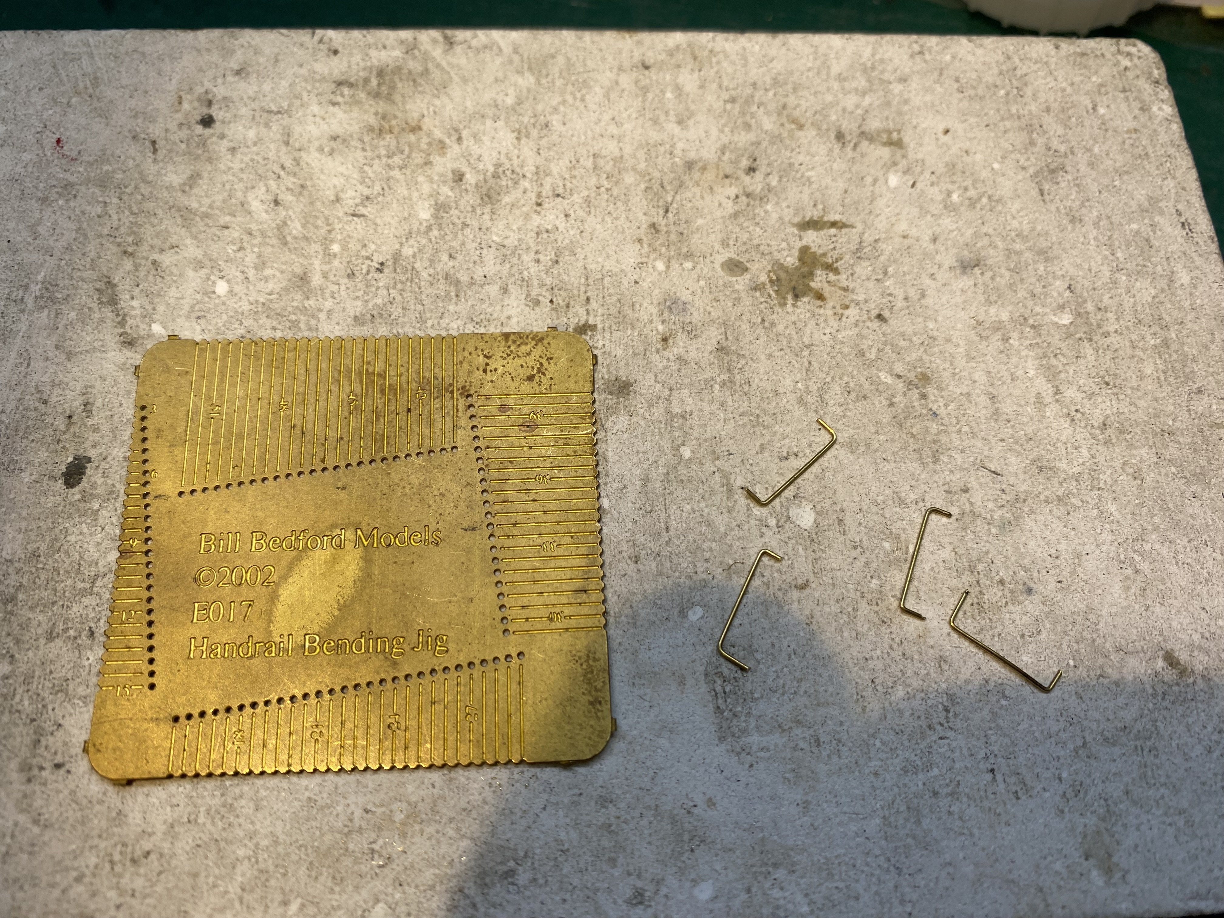
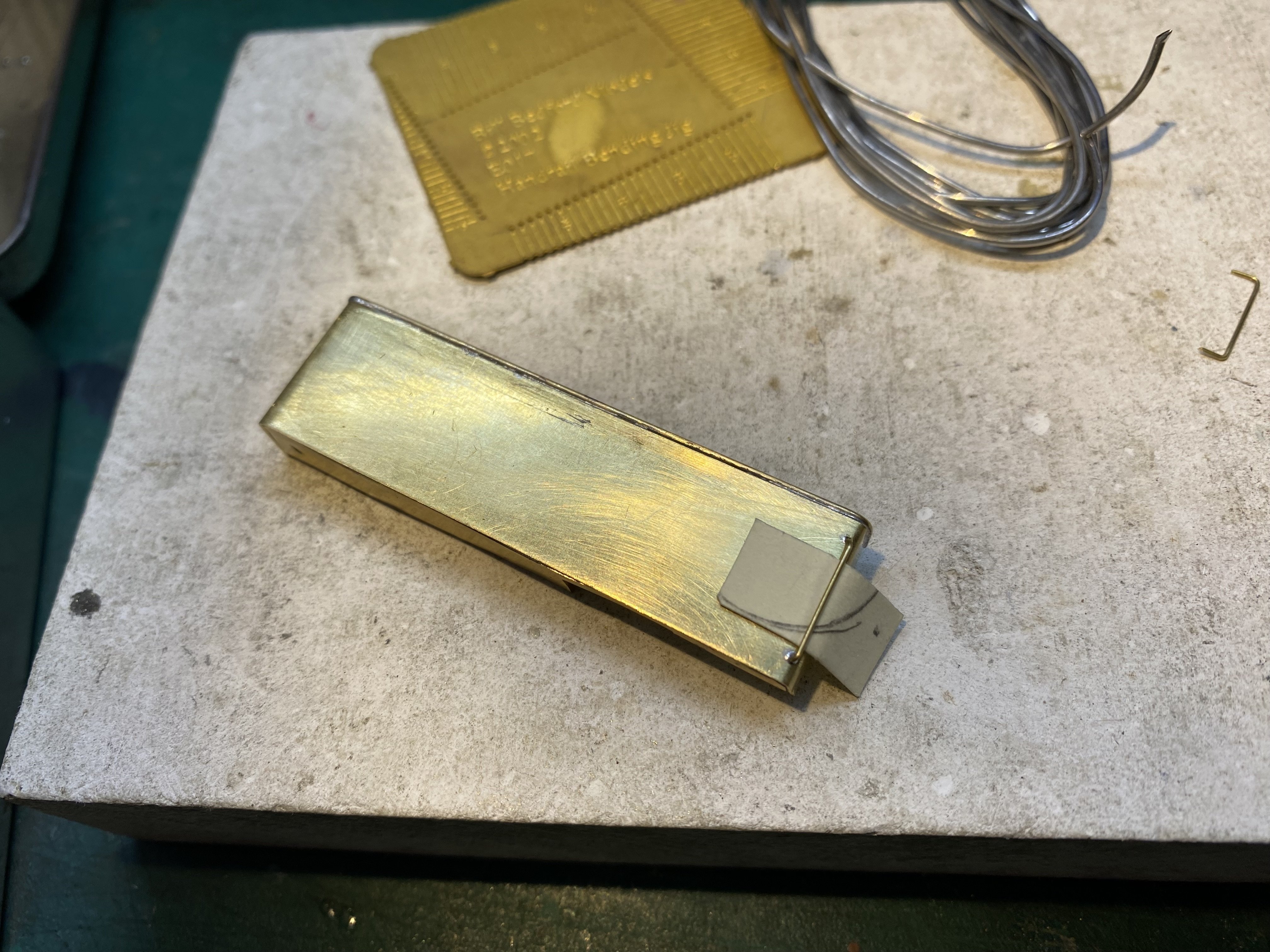
Water tanks taking shape. 15 thou brass with 0.7mm brass rod for the beading. I find matching handrails to their holes a bit of a challenge. This handy little Bill Bedford jig helps. The tanks bolt down to the running plate at the front and will be soldered to the cab sides and front. Alan
- 613 replies
-
- 13
-
-
-
On my Hornby Railroad Jinty, which admittedly is pretty old, the large couplers are held to the chassis at each end with a single screw and easily removed, leaving a space for the coupler of your choice, either screwed or glued in place. Assuming nothing has changed, the Mark's Jinty should also be easy to modify. Getting hold of NEM sockets is harder in my experience. Sources, anyone? Alan
-
I may follow your lead on that John. The smaller ones get harder and harder to see as time goes on!
-
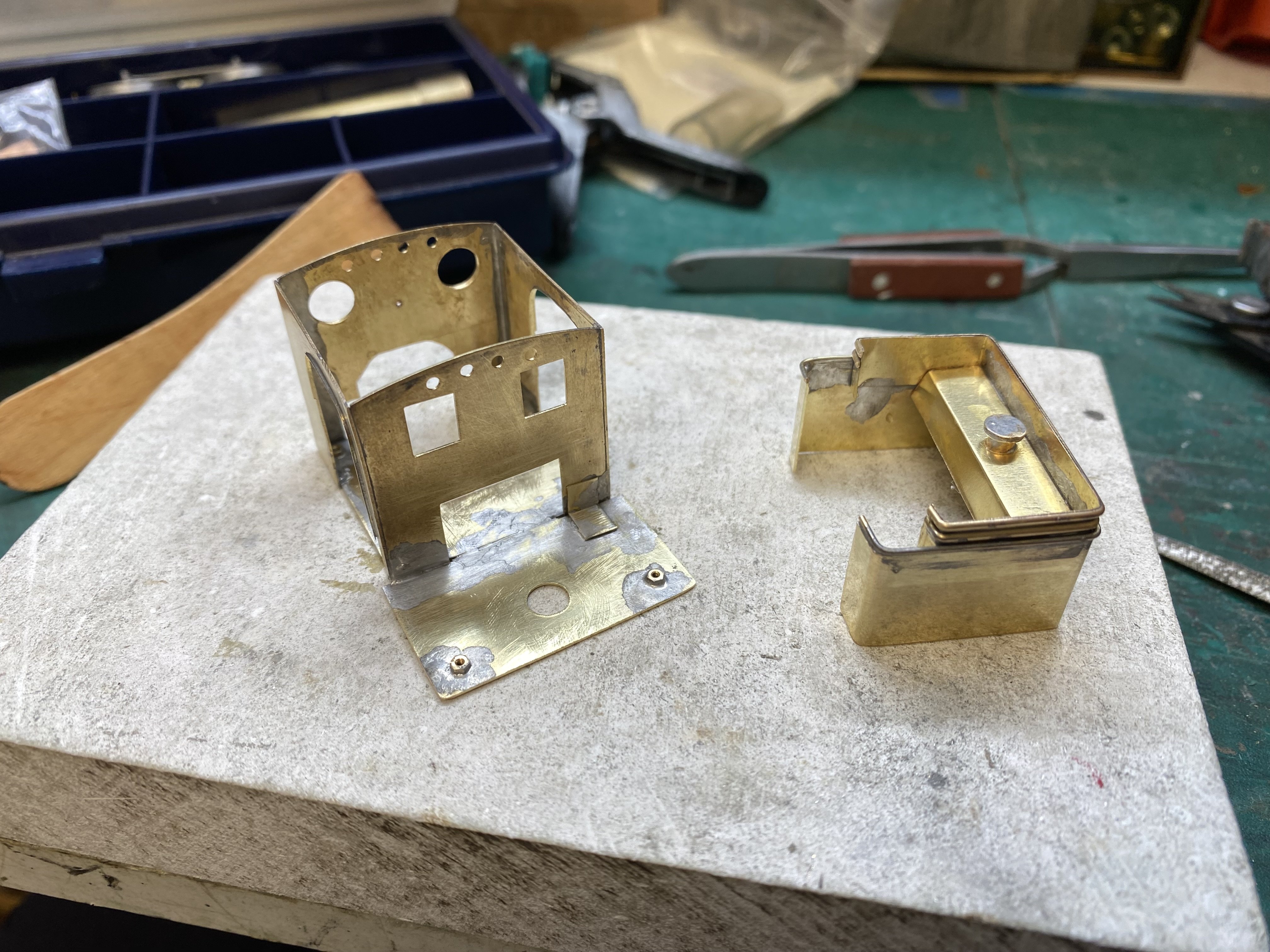
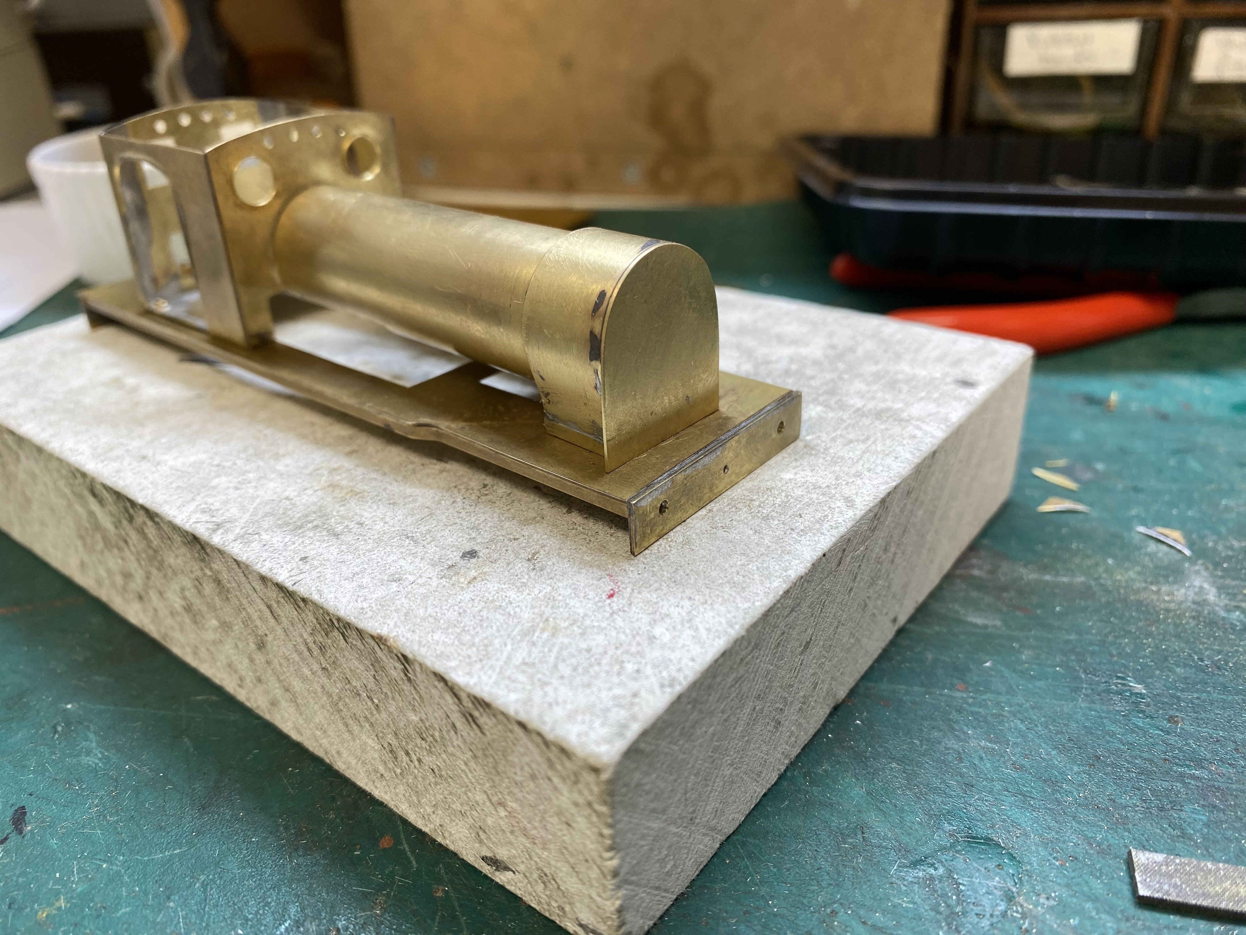
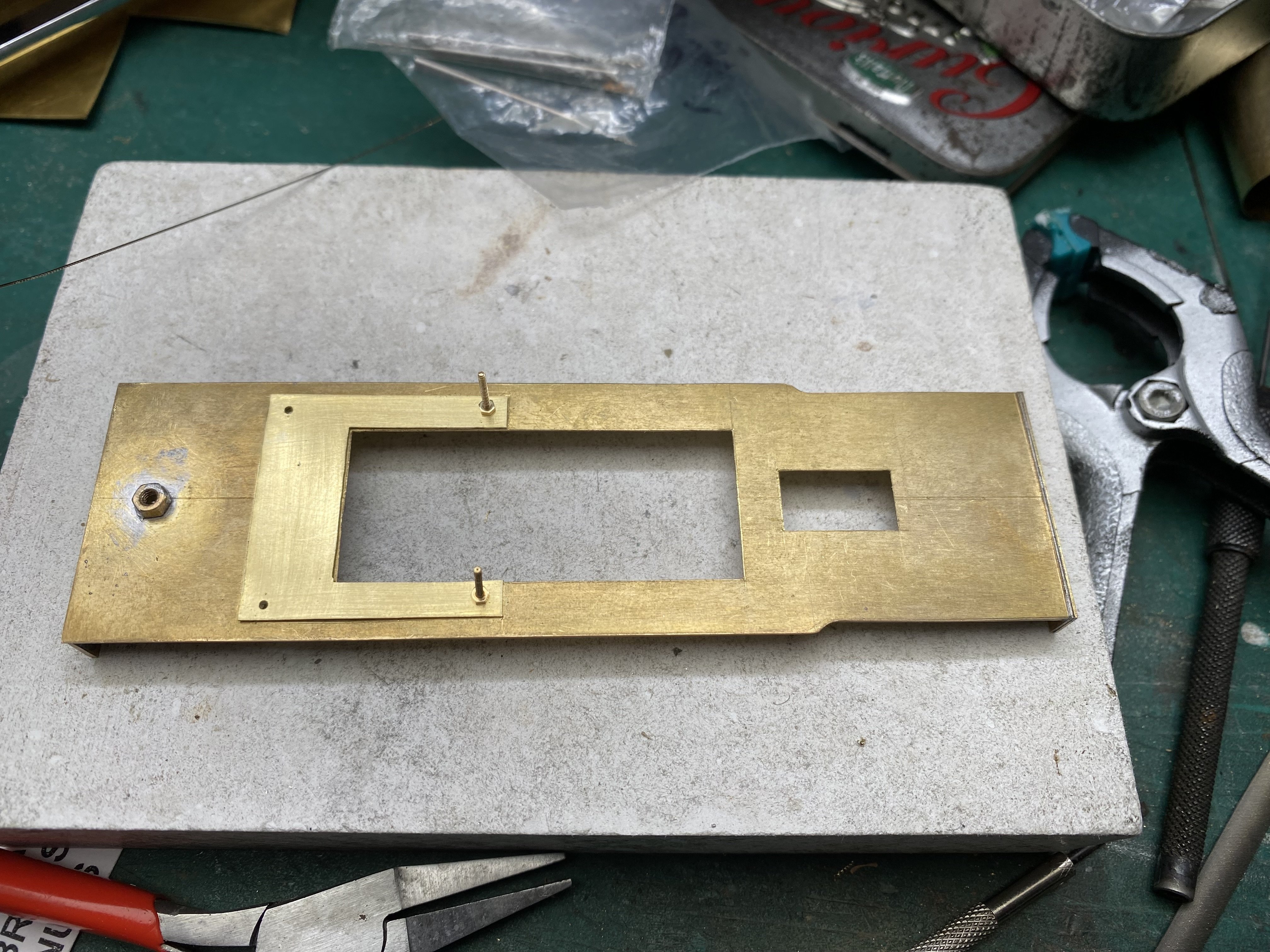
A bit more progress with the 2-4-2T. A front plate for the smokebox required a lot of solder, a lot of filing and significant amounts of unseemly language. The finished job conceals a multitude of sins. Next, the beginnings of a pair of water tanks. There's a lot of 14BA bolts and captive nuts holding this one together - founder members of the Little Things Sent To Try Us club - but having separate sub-sections makes painting and lining a lot easier. Alan
- 613 replies
-
- 16
-
-
-
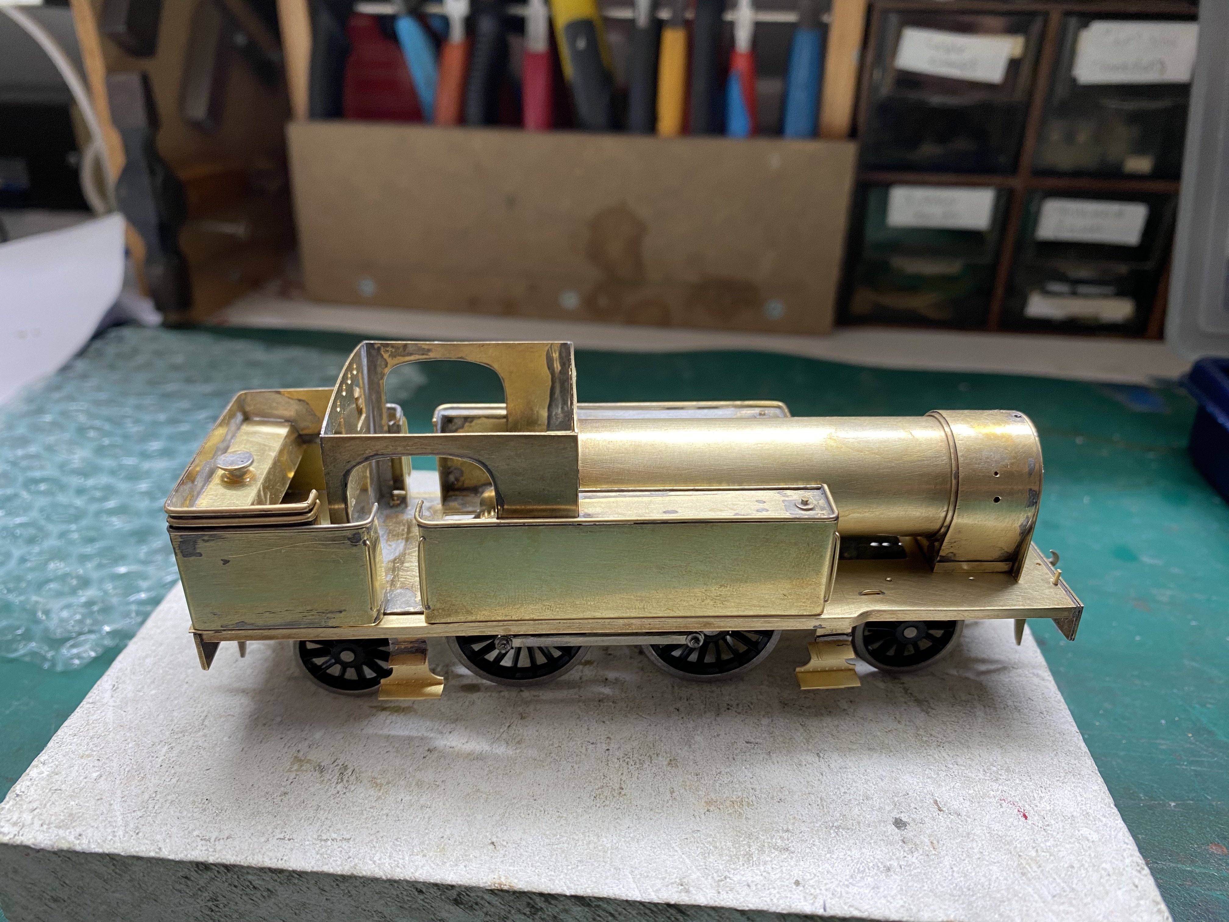
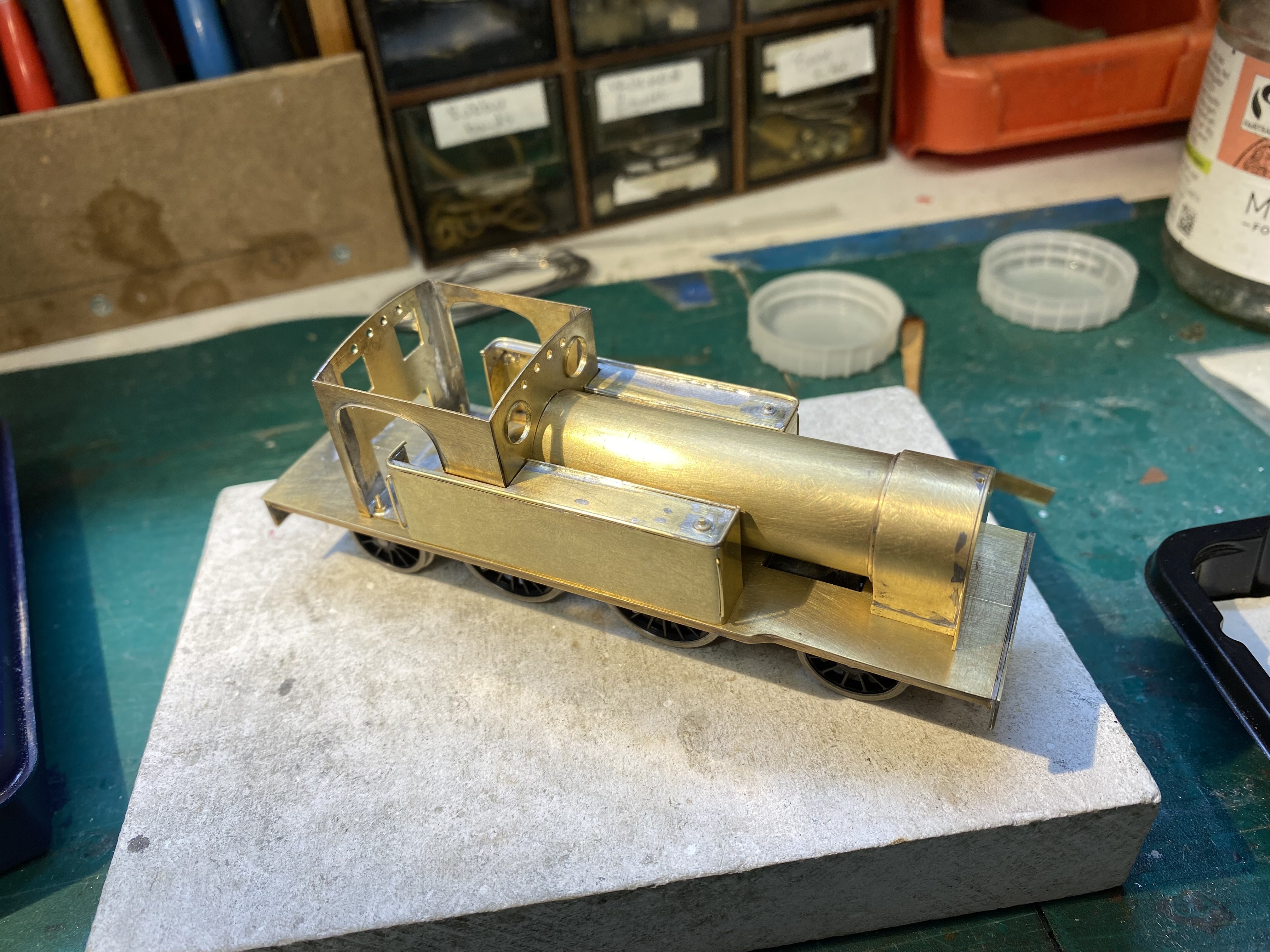
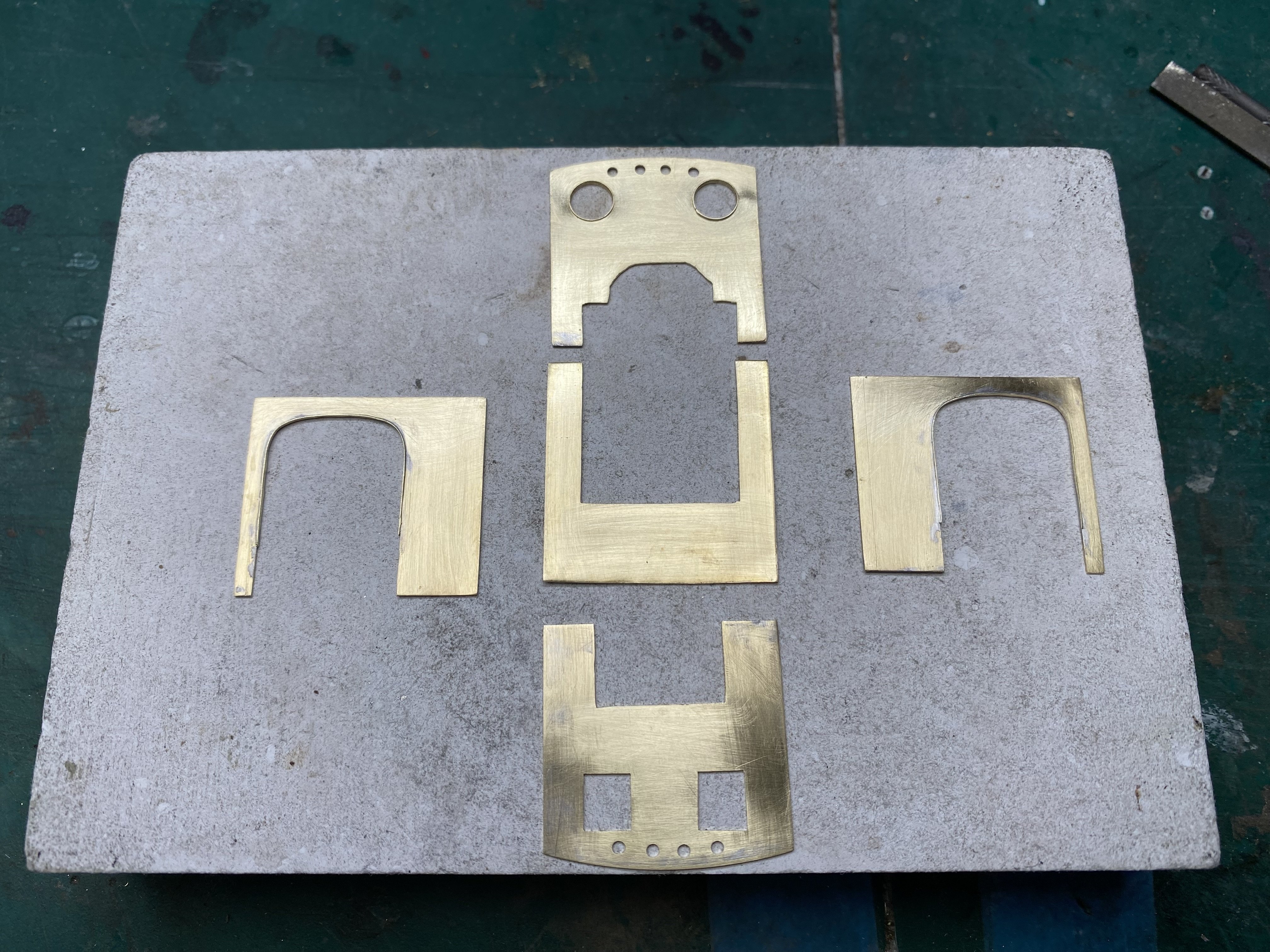
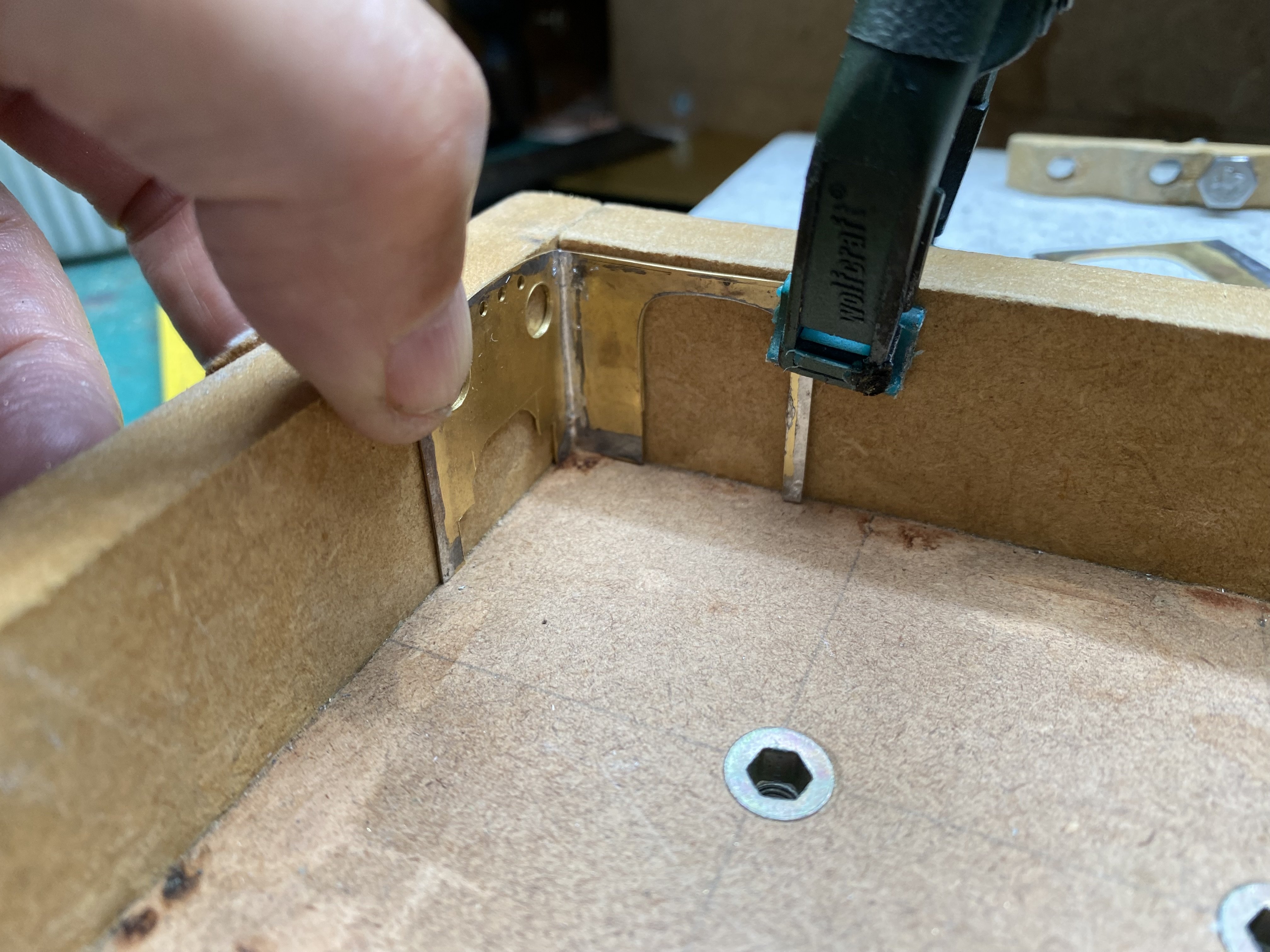
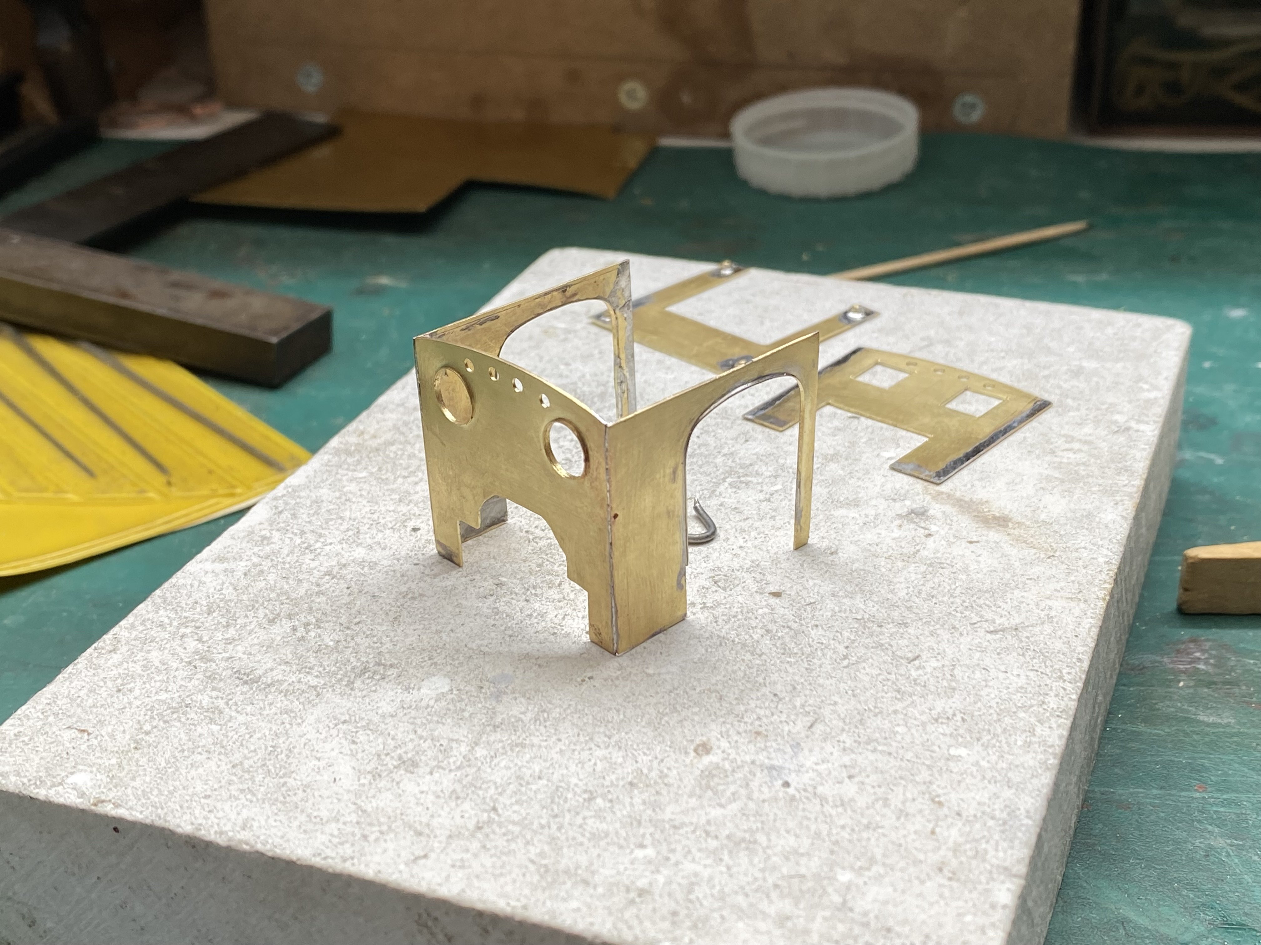
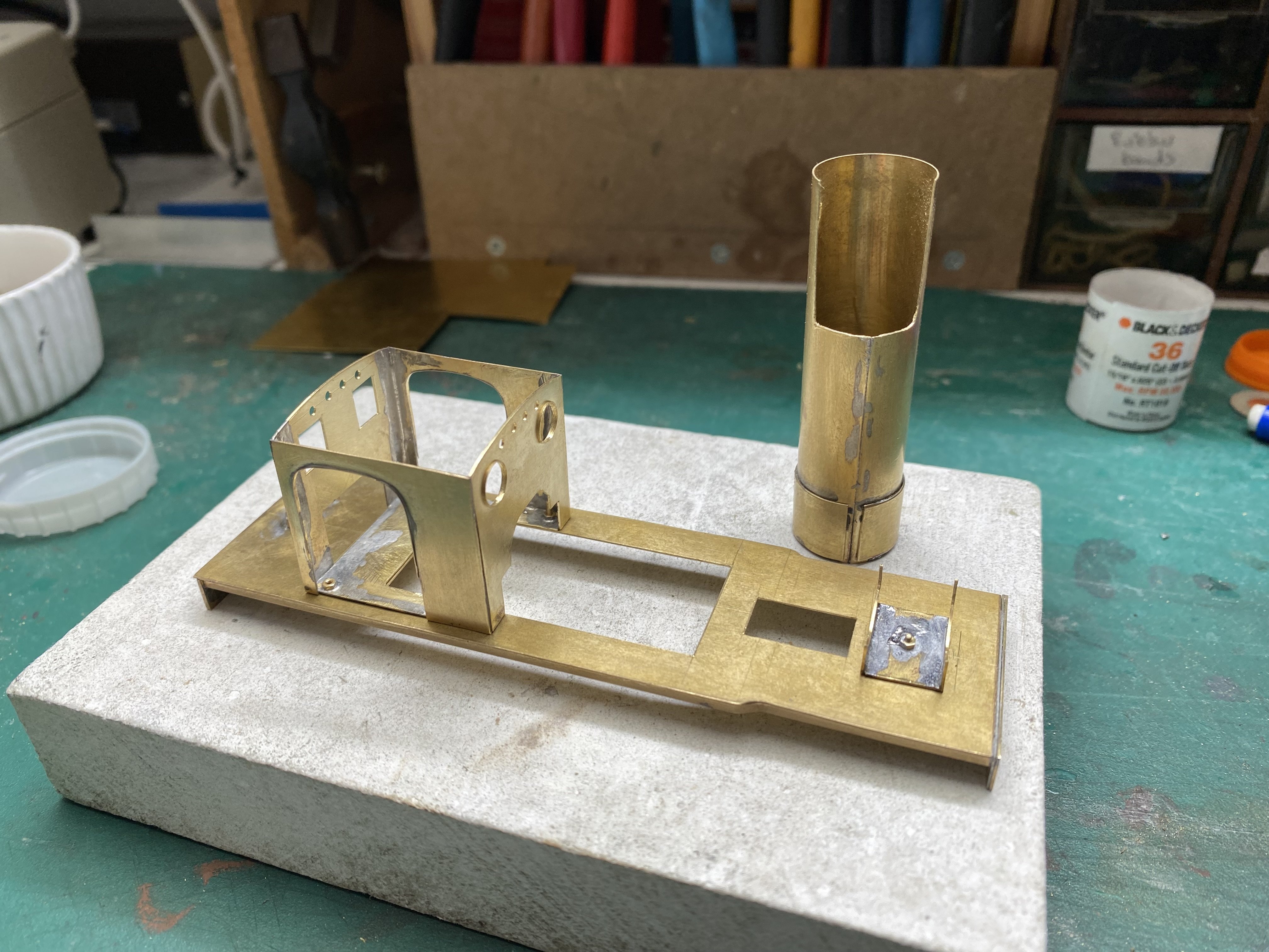
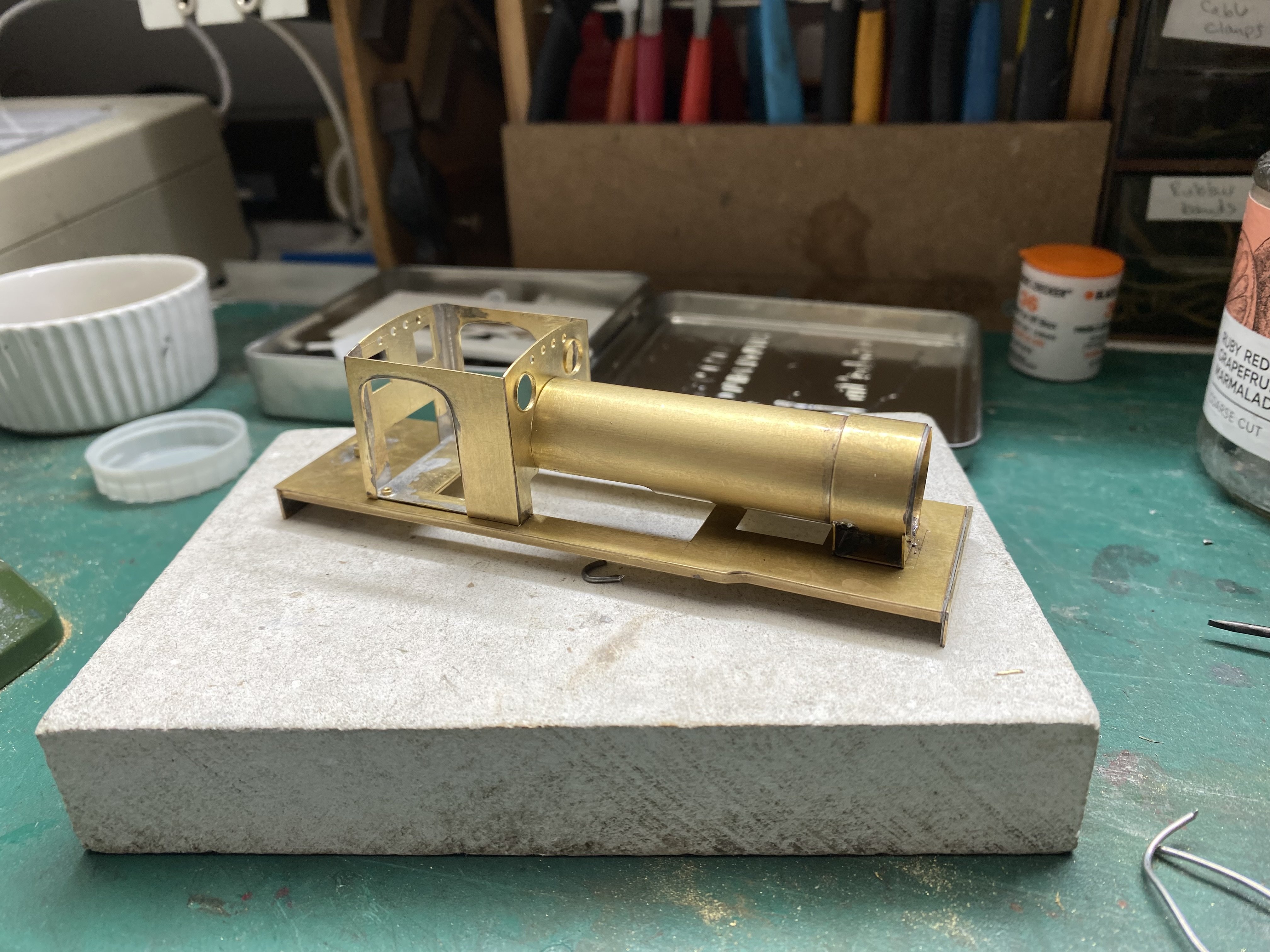
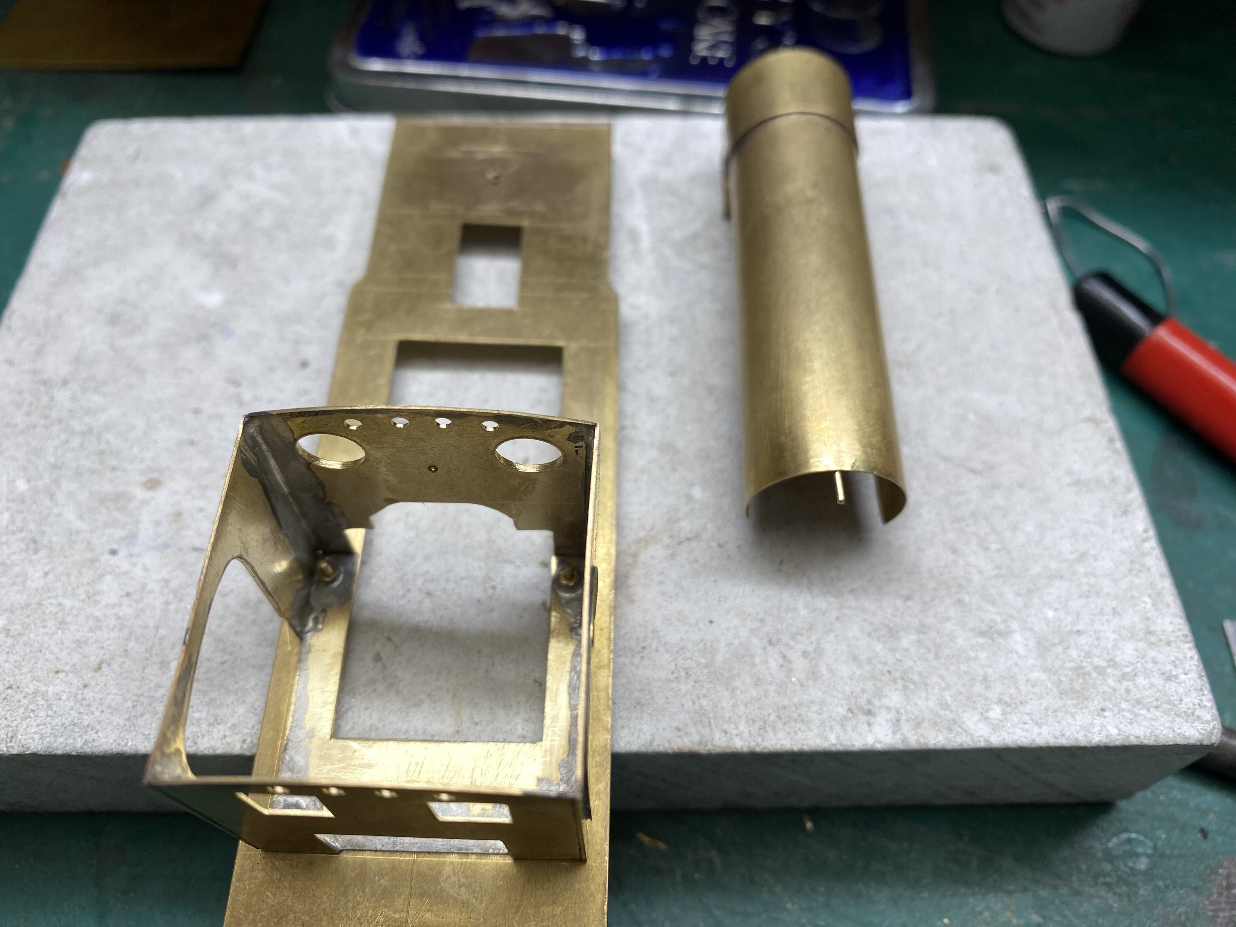
Time for some superstructure for BCDR 2-4-2T. A boiler was rolled from 10 thou brass with 15 thou used for the smokebox. A twist of brass wire held both together tightly while solder was run in at the edges. The smokebox will get a wrapper in due course. Much cutting, drilling, filing and under-the-breath muttering produced a flatpack set of parts for the cab. 15 thou brass again with 5 thou shim for the cab side beading. The raised rims round the front spectacle windows were a happy side effect of reaming the holes to size and just needed filing back a bit and tidying up to make an acceptable representation of the window frames. Saved having to solder bits of tubing into the holes. Then the tricky job of soldering it all together reasonably straight and square. Always a challenge and requiring a fair bit of adjusting and doing again. Not to mention asbestos fingers. The cab floor will bolt to the running plate using 14BA bolts with captive nuts. Holes were drilled and nuts soldered in place before the floor was soldered to the cab. Getting all the bits in the right place relative to one another is, for me anyway, a process of trial and error with plenty of the latter before it comes good. I find making and fitting the saddle which supports the smokebox a real trial. Luckily, the smokebox wrapper, which will blend smokebox to saddle, will hide most of the bodgery. A length of 0.7mm brass rod soldered inside the boiler slots into a hole in the cab front to hold the boiler straight and level. I think it's teatime. Alan
- 613 replies
-
- 16
-
-
-
Thanks David. The High Level gearboxes are wonderful little devices and I nearly always use them but they do need careful building. I think we've all managed to get glue in the wrong place at least once. And those grub screws seem to have a life of their own. I lost one earlier in this build and against all the odds, found it again by trawling the carpet with a magnet!
-
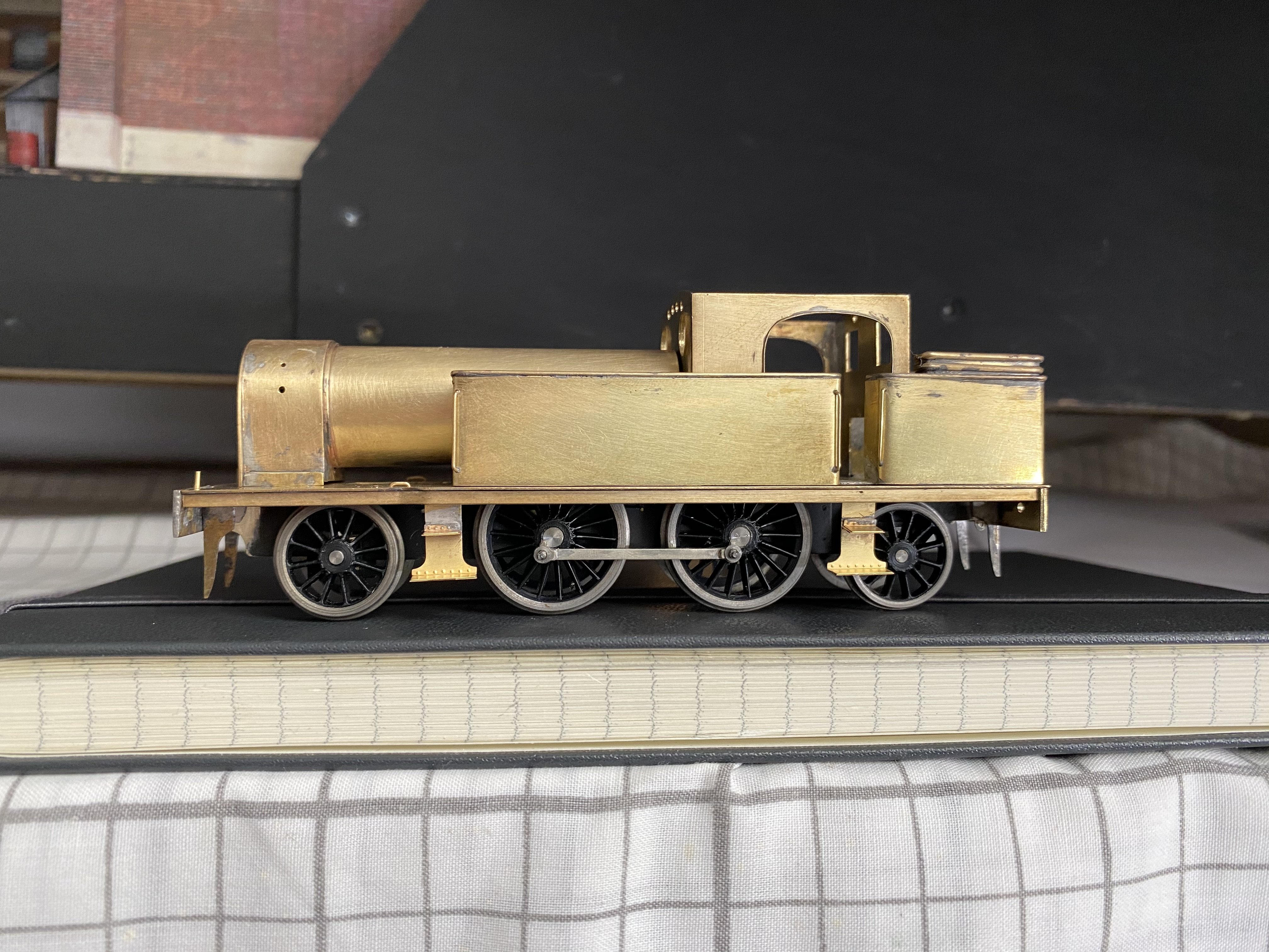
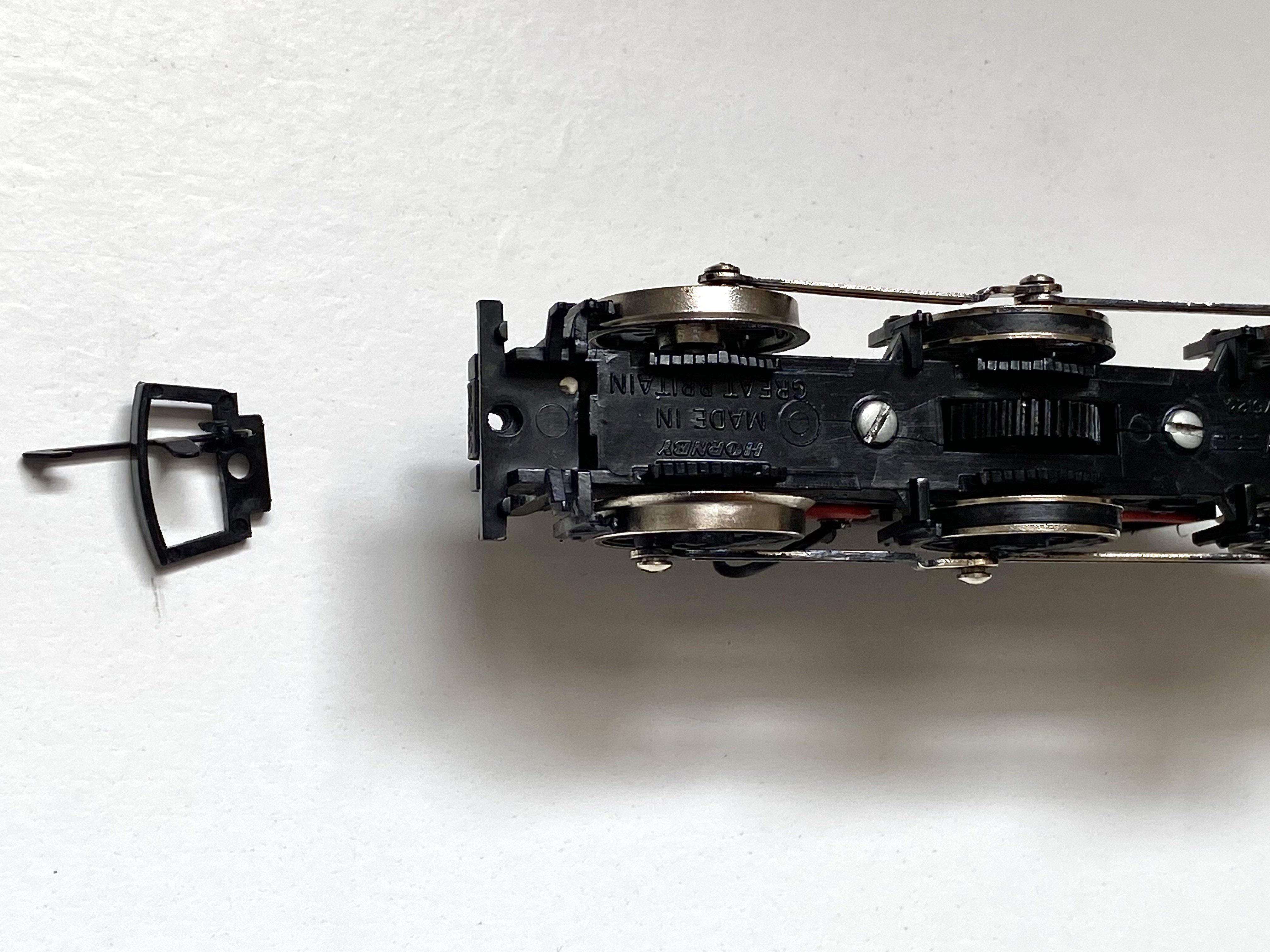
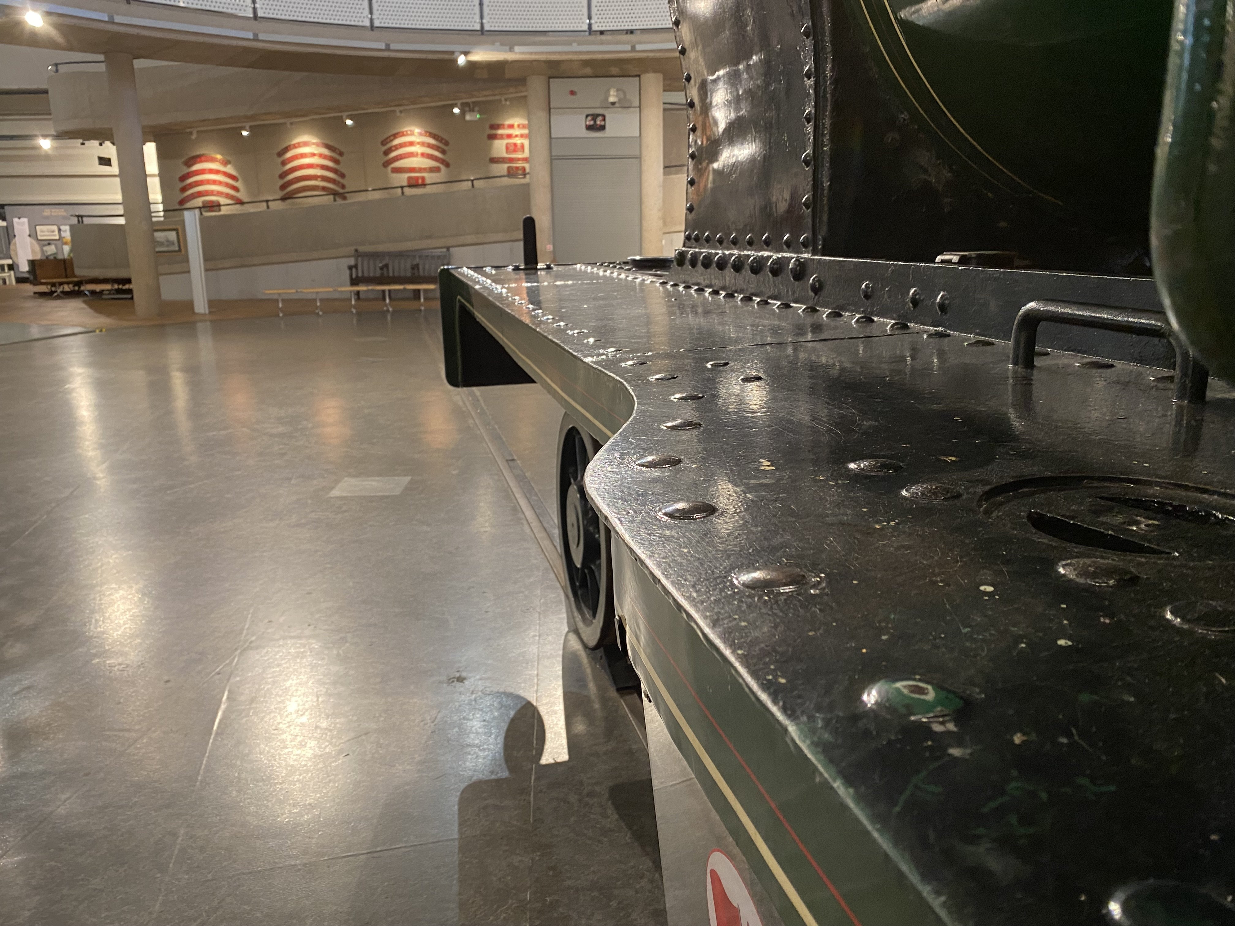
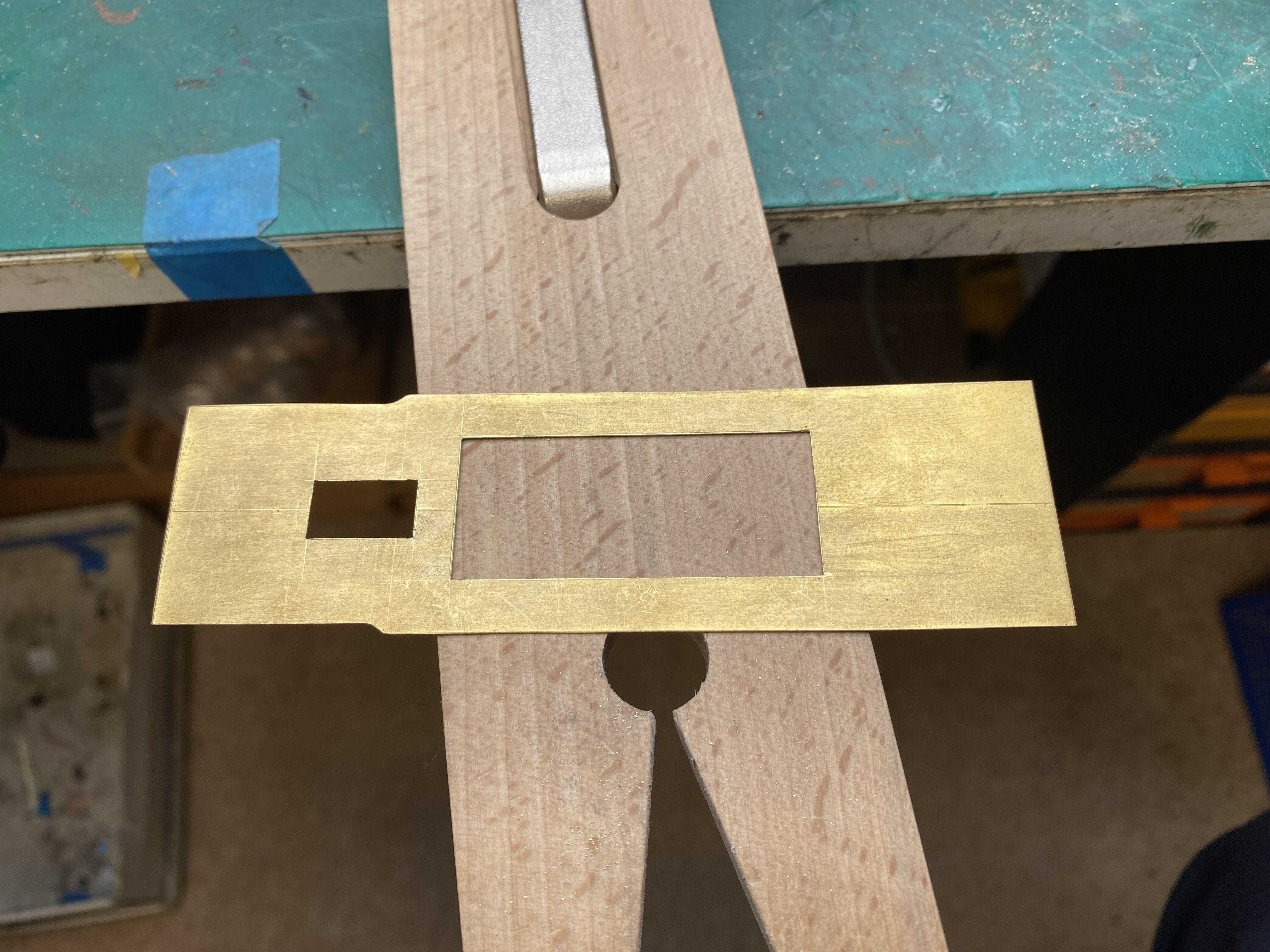
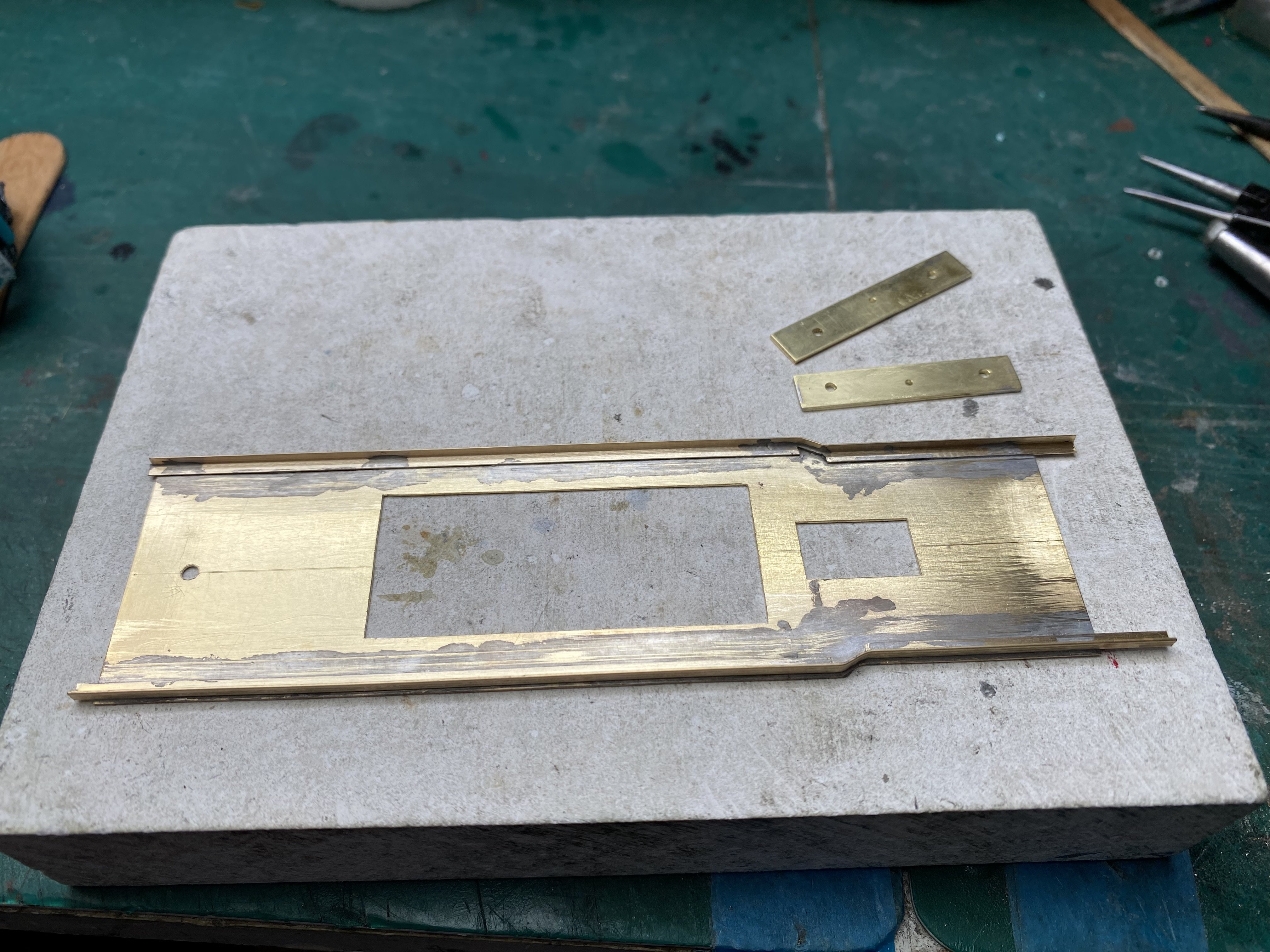
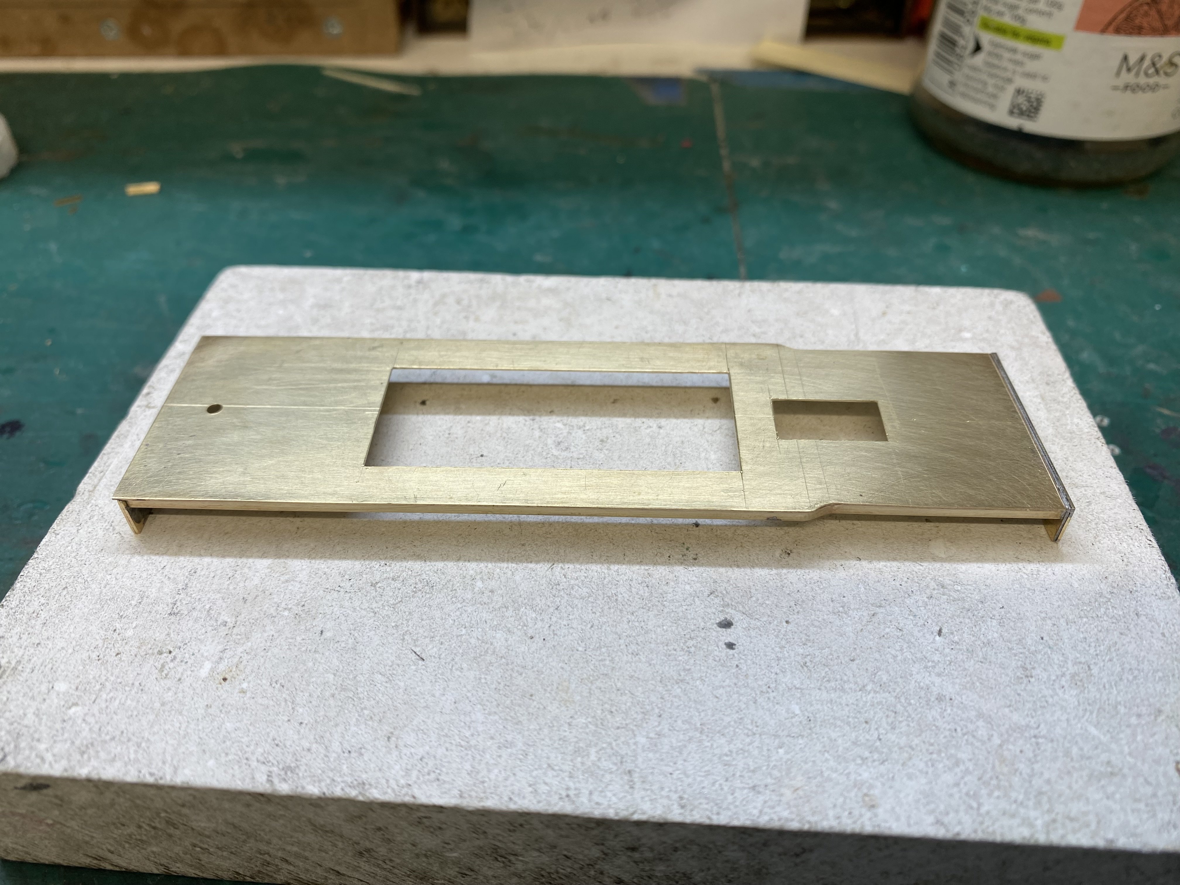
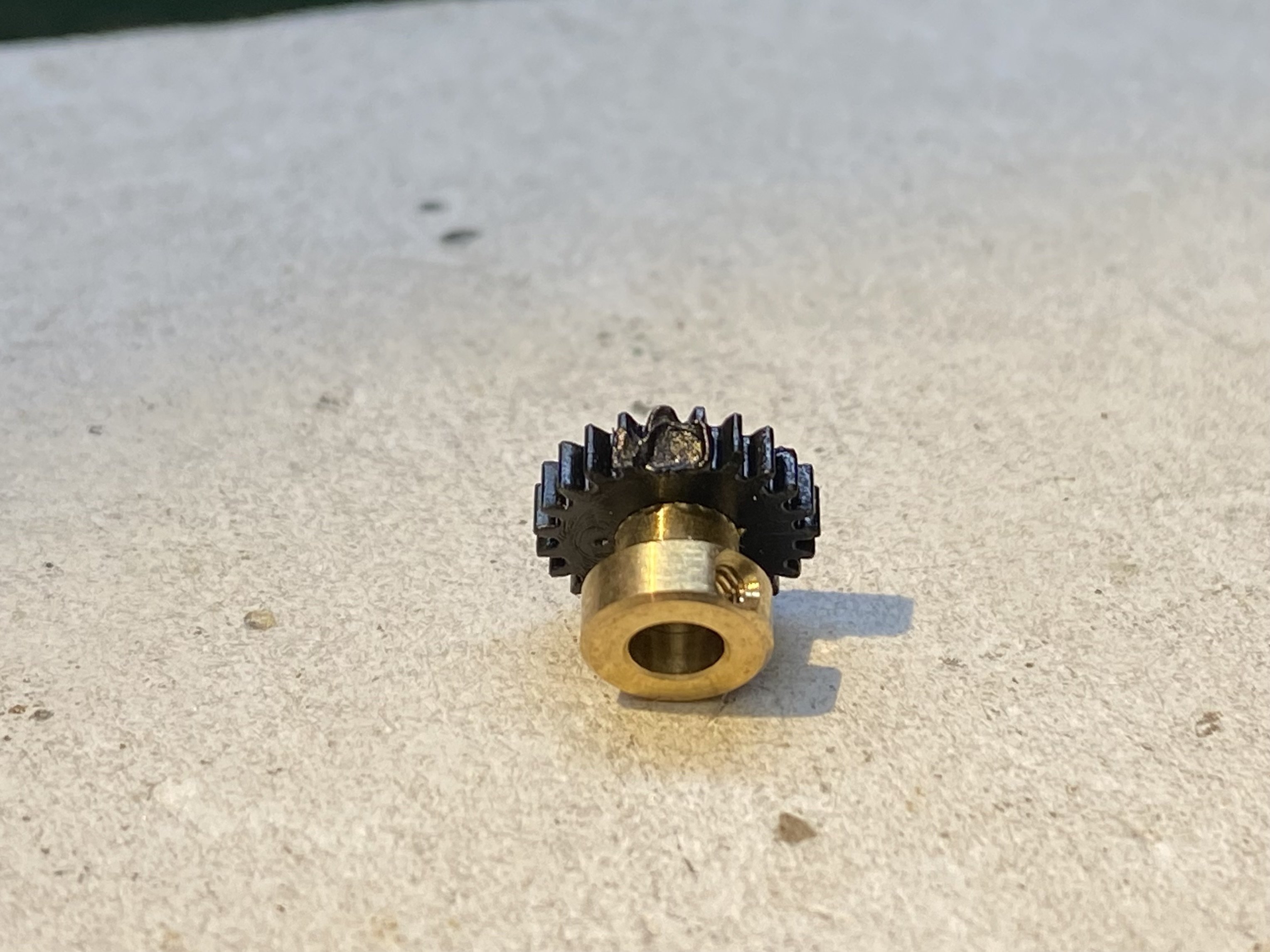
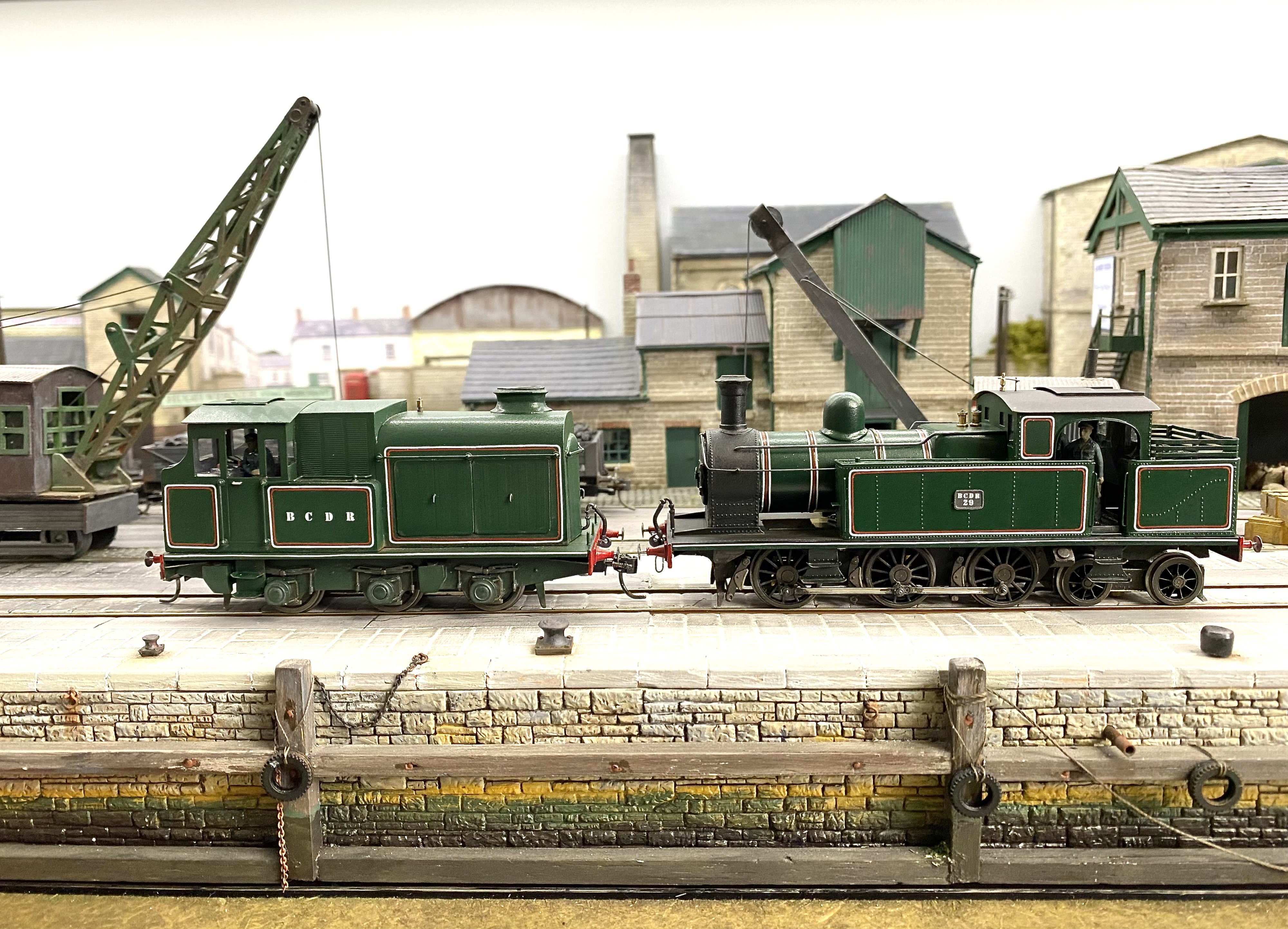
The BCDR 2-4-2T progresses slowly. I soldered guard irons and brake hangers to the chassis - all a bit of a faff because they should've been done before the gearbox went in and the wheels went on. Anyway, after all the mucking about I checked the chassis was still running ok. Was it? Nope! One half revolution of the wheels and it seized up. Couldn't see what the problem was at first but eventually traced it to this... Seems I'd been waving the soldering iron around like Harry Potter's wand and managed to melt some teeth on the final drive gear without even noticing. Clumsy? One yeah! Minus 1000 brownie points and no supper. Luckily, High Level sell spares and in the meantime, I borrowed a replacement from an unbuilt gearbox in the to-do drawer to keep this project on the rails. Next up, the running plate, made from 15 thou brass sheet. In common with the later BCDR bogie tanks, the running plate on the 2-4-2T narrows just ahead of the water tanks. This is No 30 at Cultra. What should have been a simple rectangle ended up taking a lot longer to do and involved filing a bit out of one flange on the 1.5x1.5mm brass angle strip used for the valances so it could be bent. The end result is more or less symmetrical but since you won't be able to look at both sides of the finished loco at the same time ... Buffer beams are two thicknesses of 15 thou brass. Now I look at that last photo, I can see a pickup wire being stand-offish with its wheel. I'll give it a severe tweezering later. Alan
- 613 replies
-
- 11
-
-
-
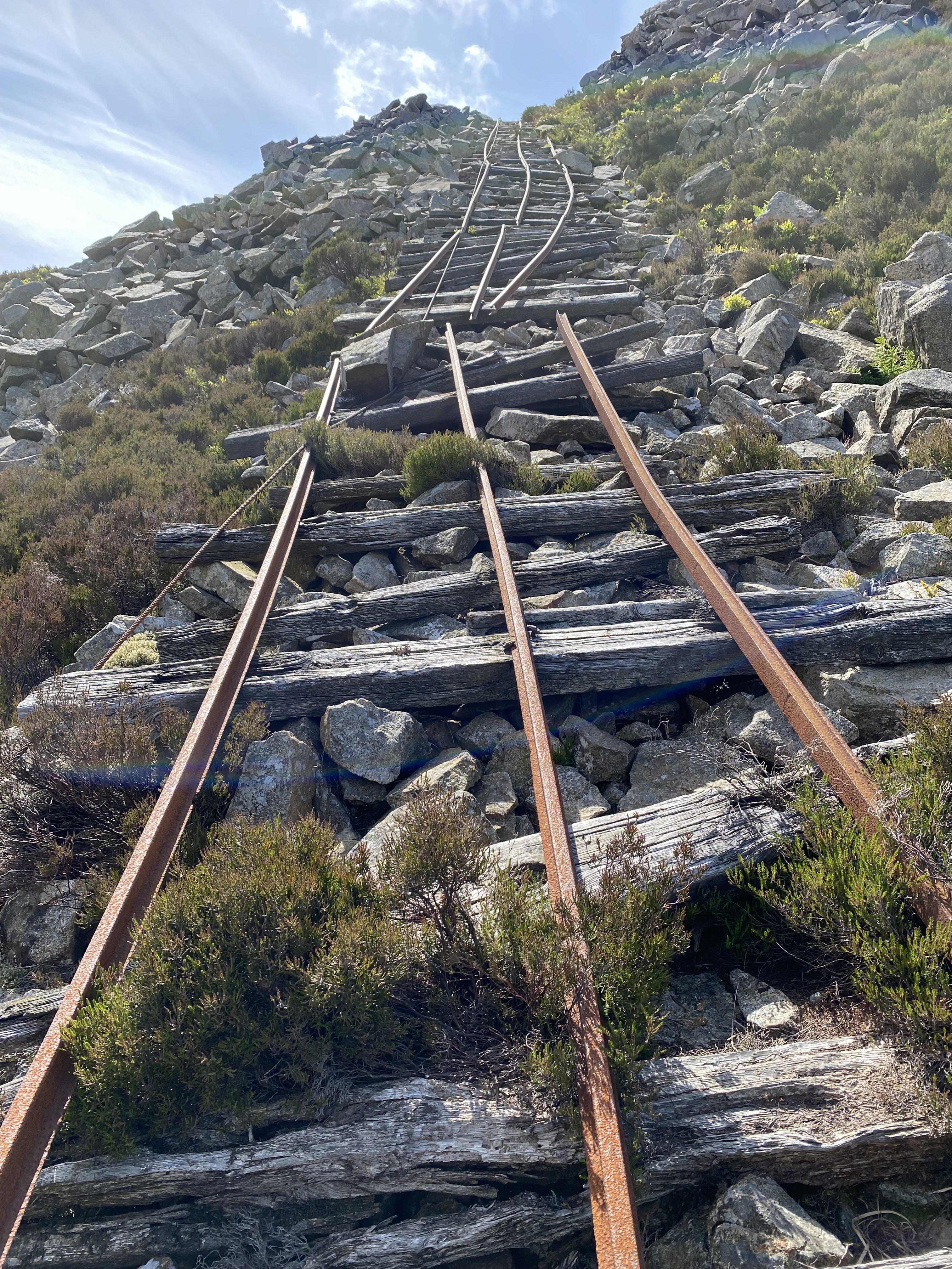
Whilst granite quarrying in the Mournes was extensive and some of the quarries are sizeable, there's nothing on the scale of the Welsh slate quarries you mention but the challenge of getting stone down the hillside would have been much the same. It didn't occur to me to measure the gauge but 3ft probably wouldn't be far from the mark. As far as I know, extensive quarrying in the area mostly ceased in the 1950s though small quantities are still occasionally taken at various sites. Carr's Face is best approached from Bloody Bridge (where some of the mountains sweep down to the sea). About a 2 hour walk, at my pace anyway
-
It's easy to miss this stuff unless, like me, you're looking for it
-
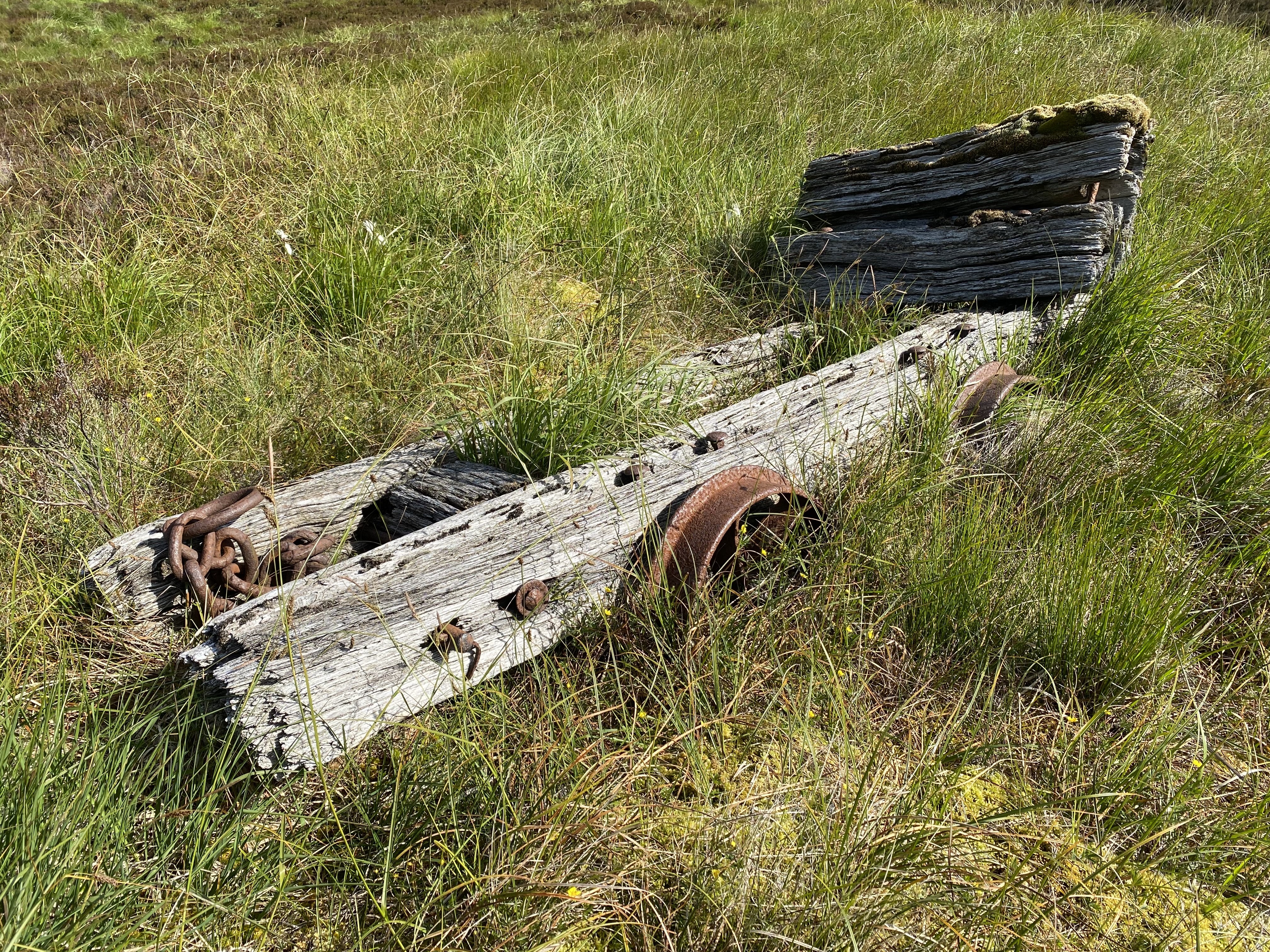
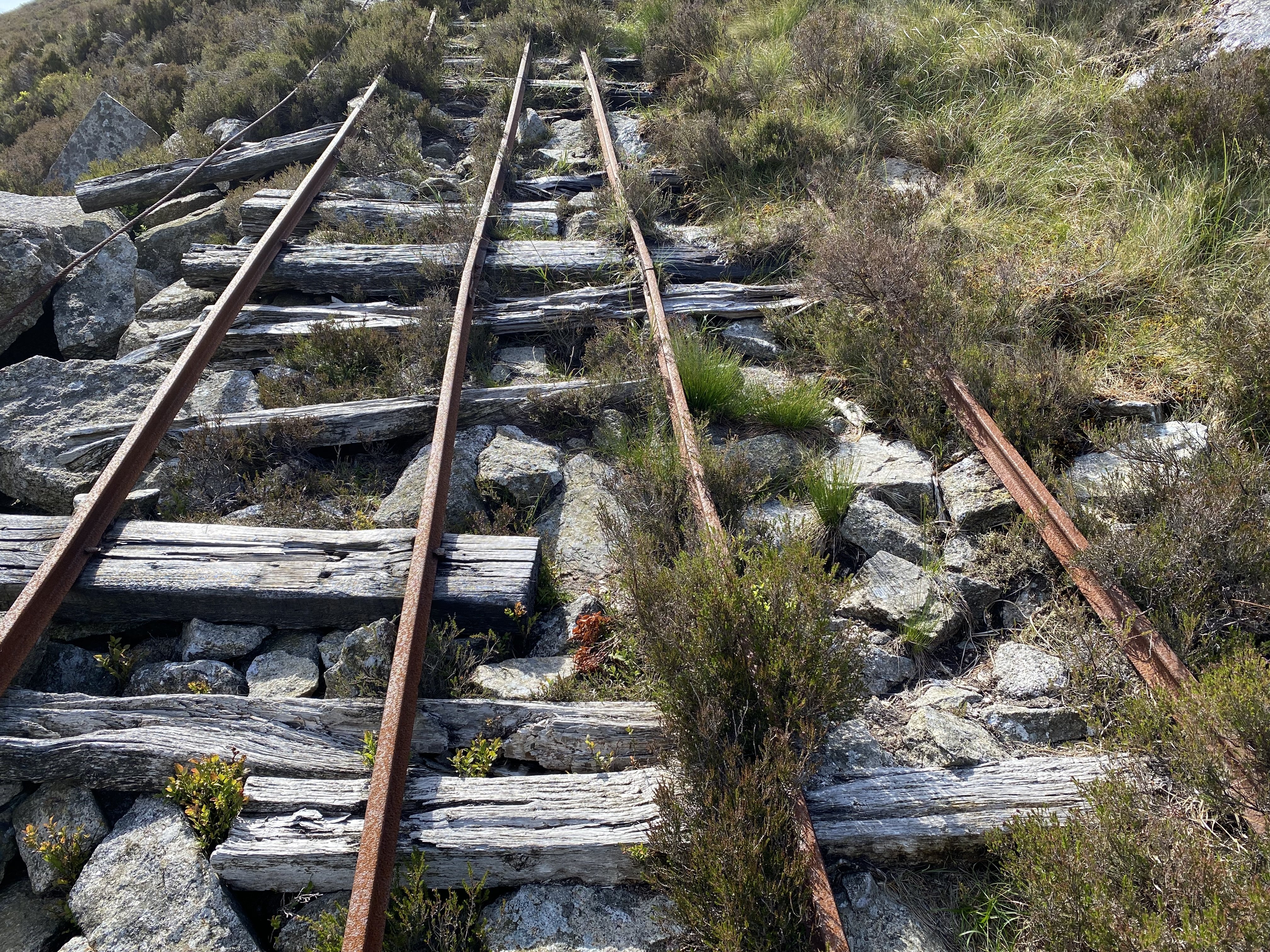
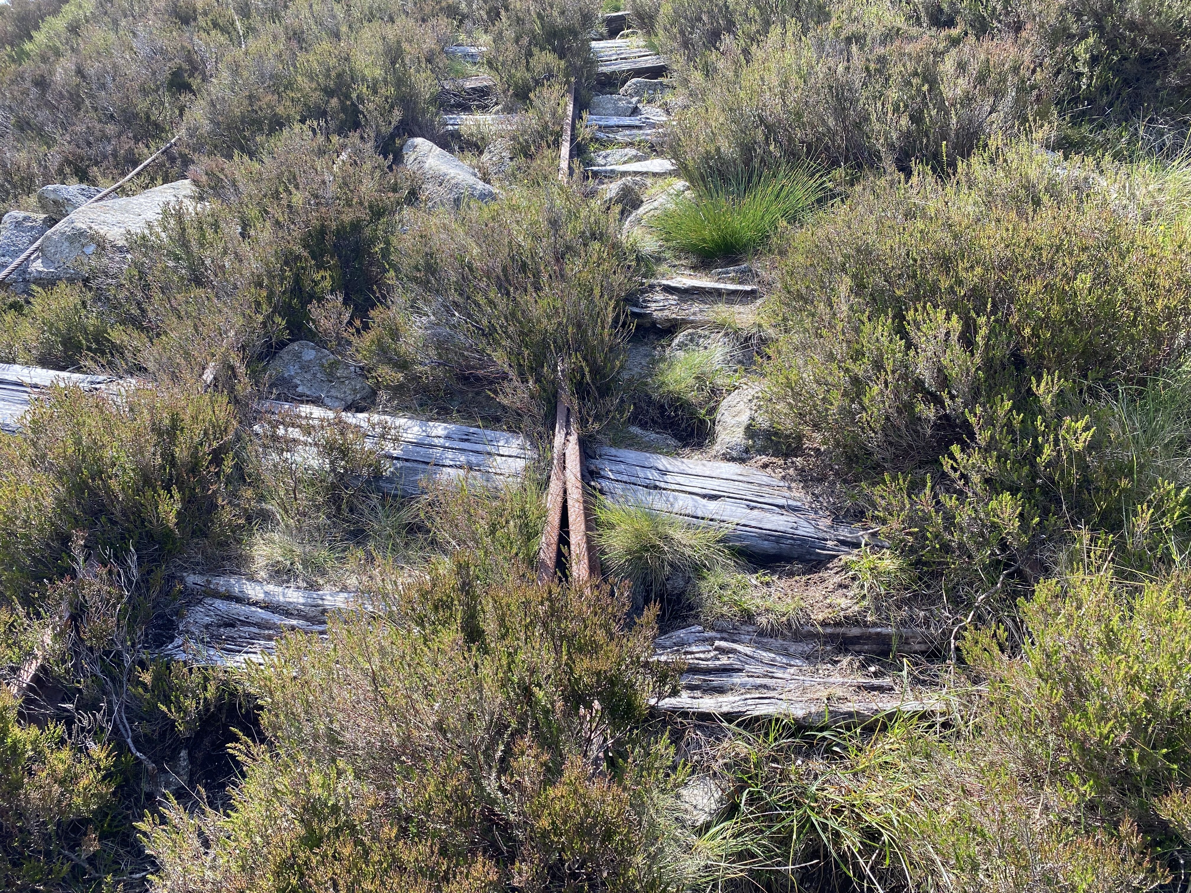
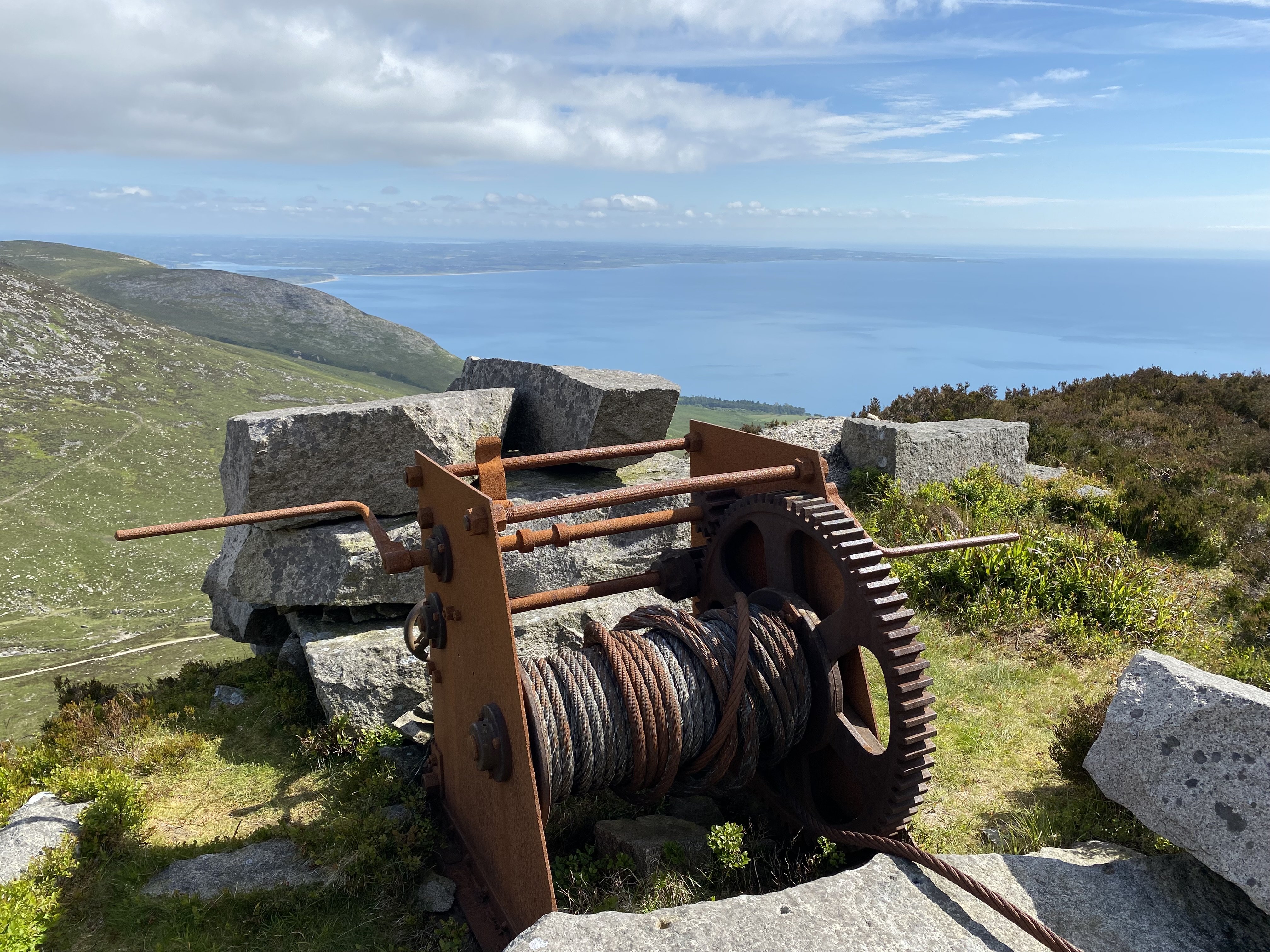
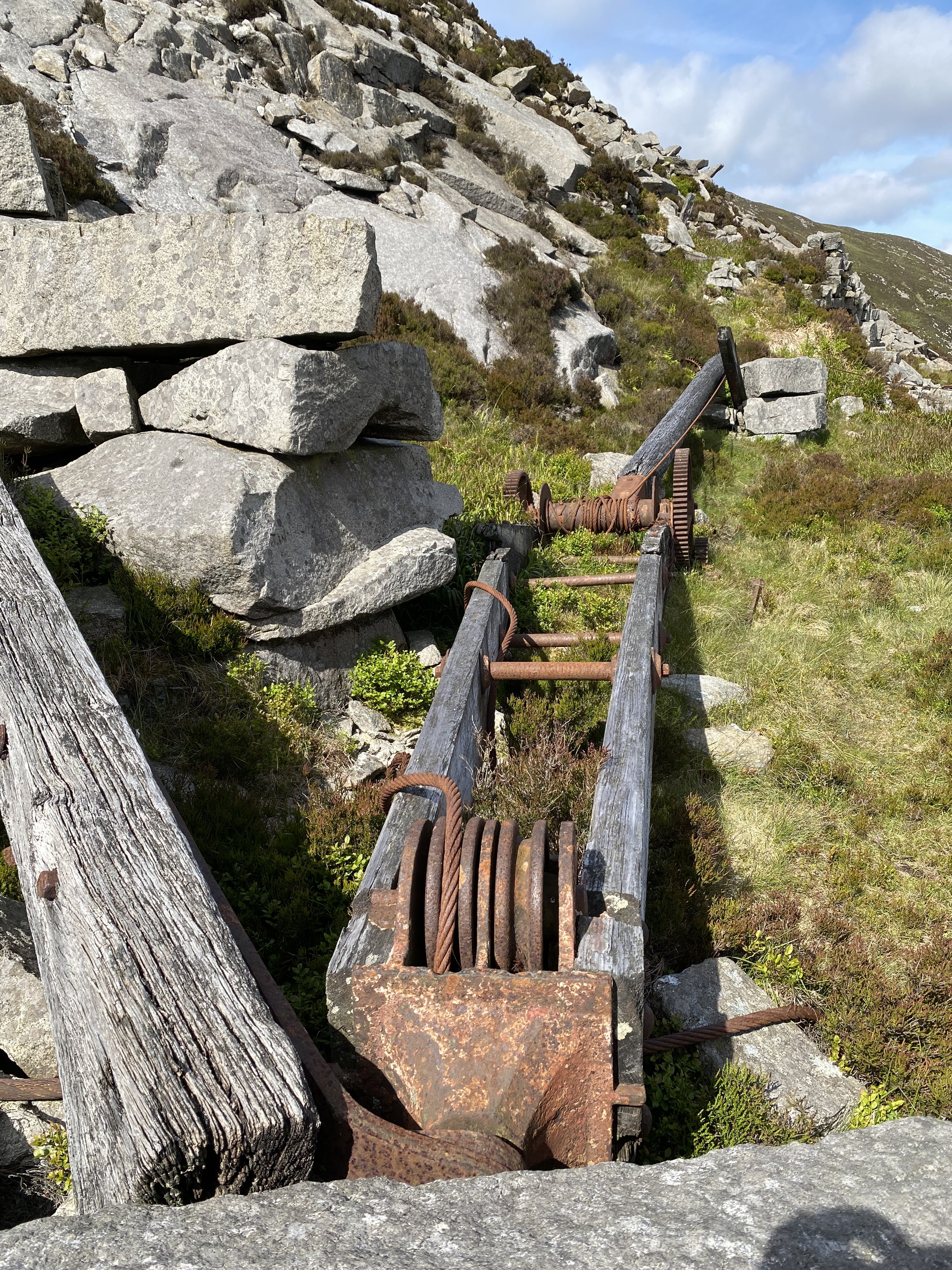
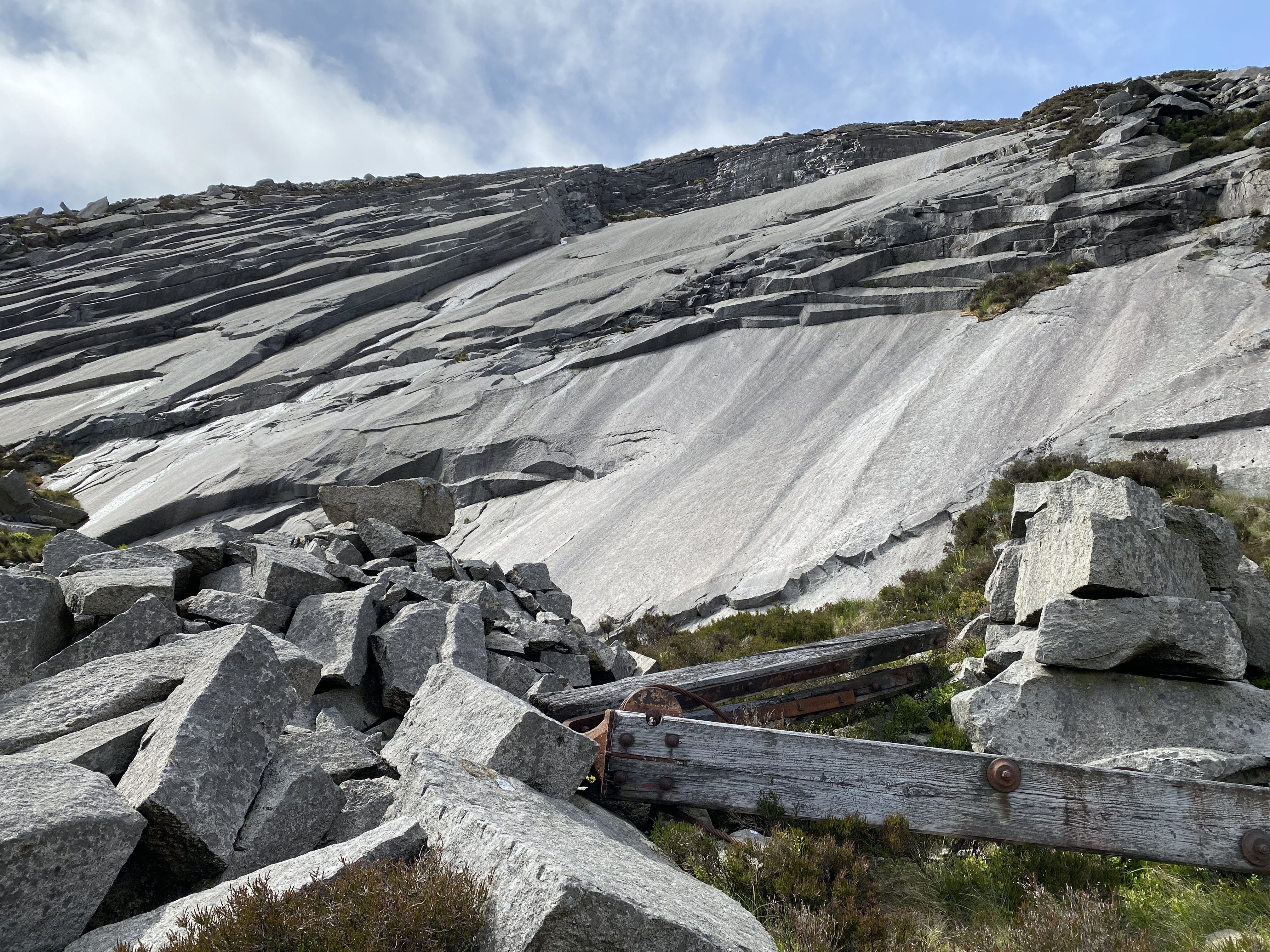
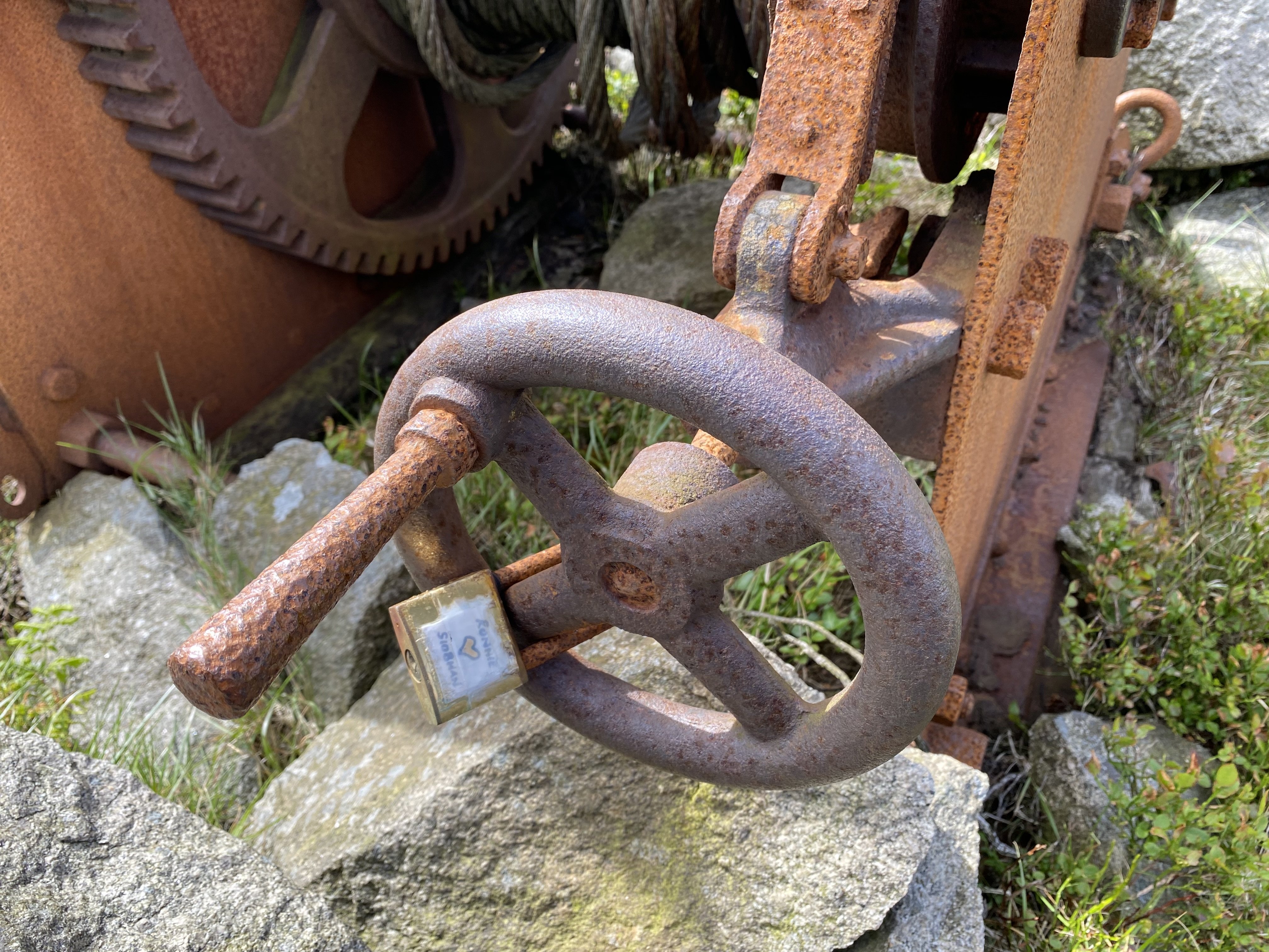
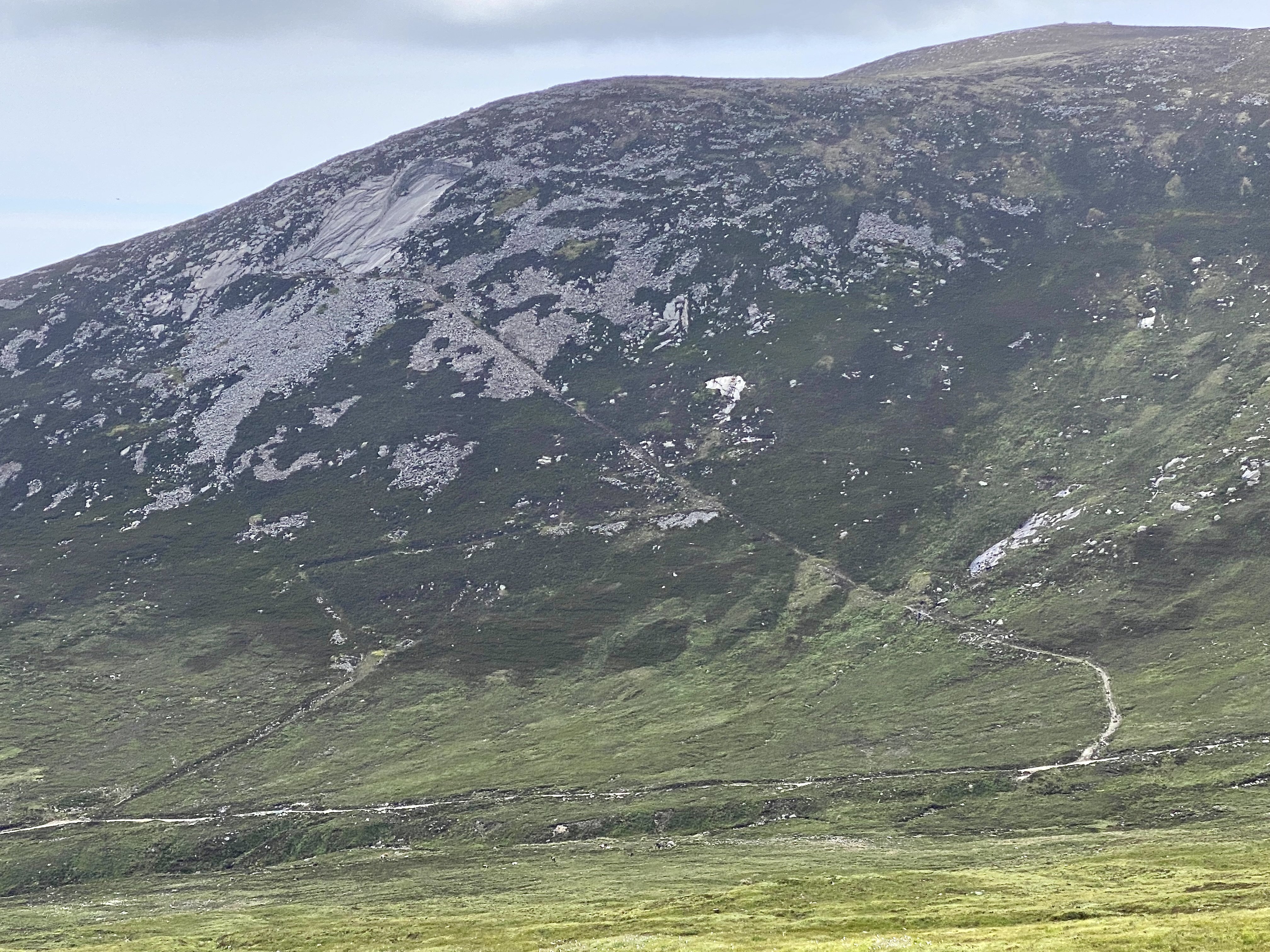
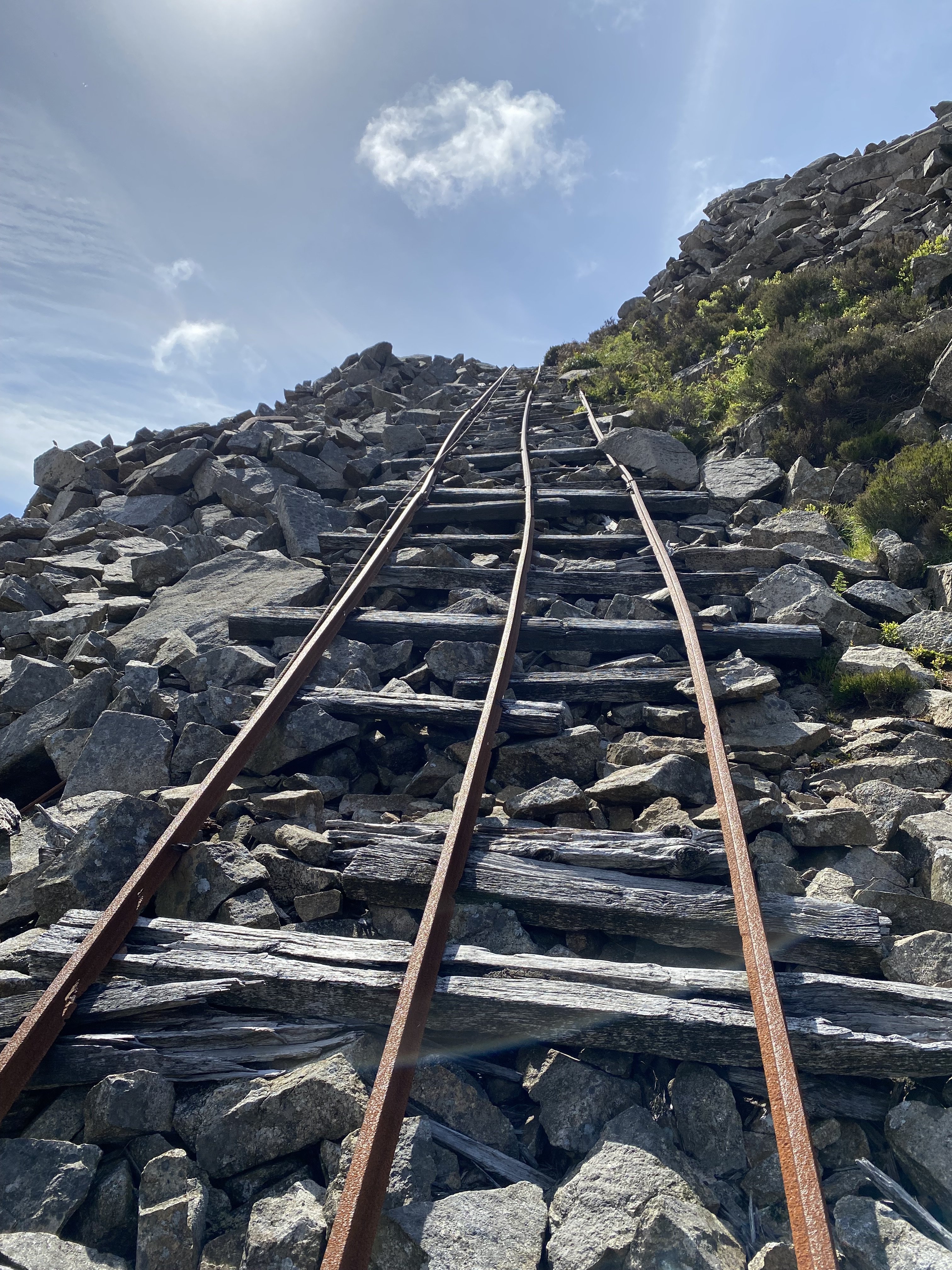
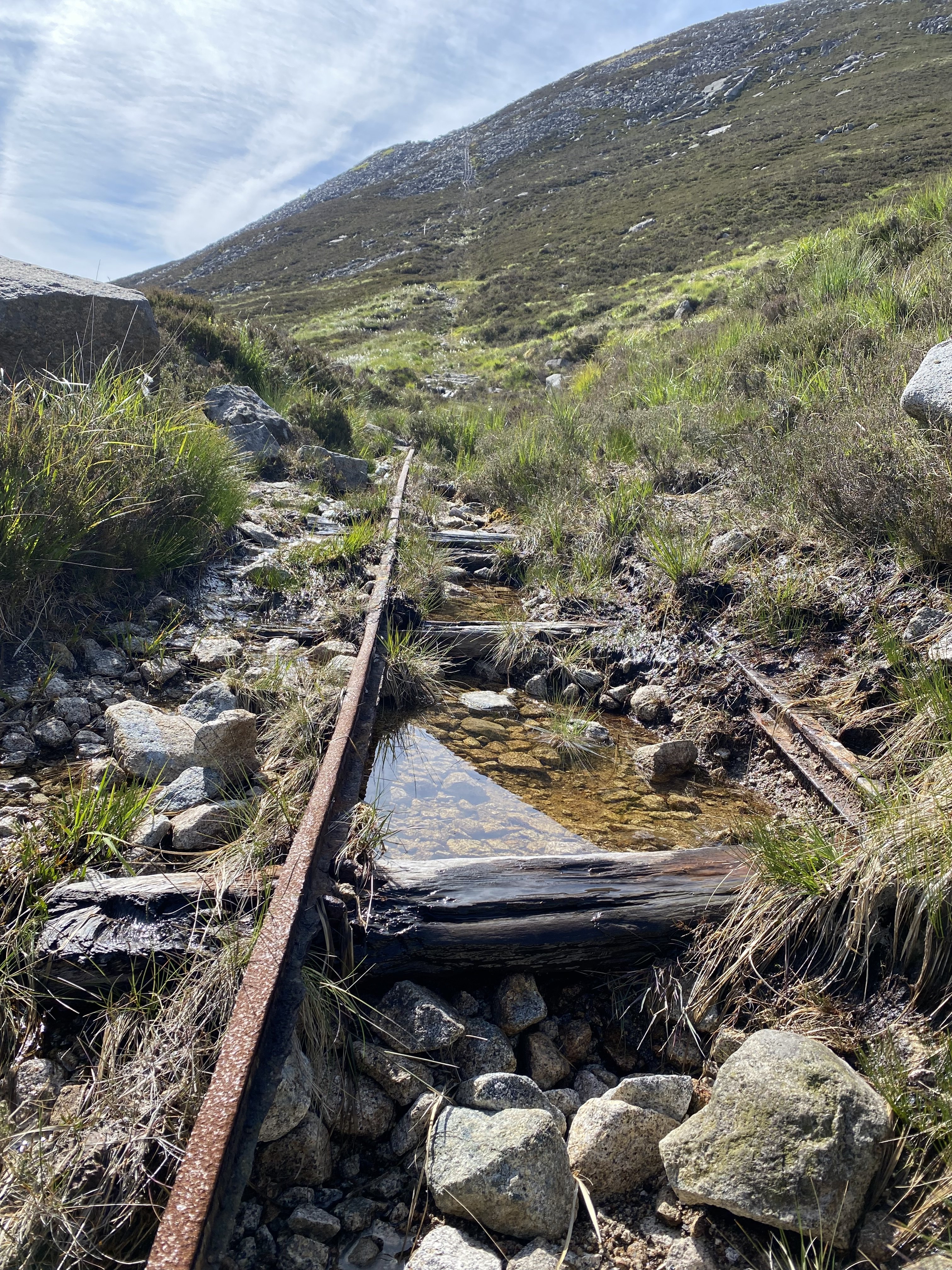
Not a locomotive in sight but this does involve rails. A sunny day today took me to the Mourne Mountains for a wander. This is Carr's Face. It's one of many sites in the Mournes where granite was once quarried. The diagonal slash up the slope is a railway used to transport stone down to the quarry track in the valley. Some rails and sleepers are still in place... ... and one of the wagons. It looks like a classic gravity system with the weight of the descending loaded wagons pulling the empty ones up, though there are pulleys and winches at top and bottom. Three rails at the top, with the centre rail common to up and down movement. Half way down, the centre rail spits into two, creating 4 rails and allowing wagons moving in opposite directions to pass one another. Seems to reduce to a single track near the bottom. I first came here about 20 years ago. Nothing much has changed in the interim. A grand day out. Alan
- 7 replies
-
- 19
-
-
-
Brilliant! I love the blending of fact and believable fiction to create a coherent system. Rewritten history or not, it's still more logical than my scattergun approach - "I think I'll build... hmmm... that" (points finger at random photograph of locomotive). I'll enjoy watching this take shape David. Best of luck with it.
-
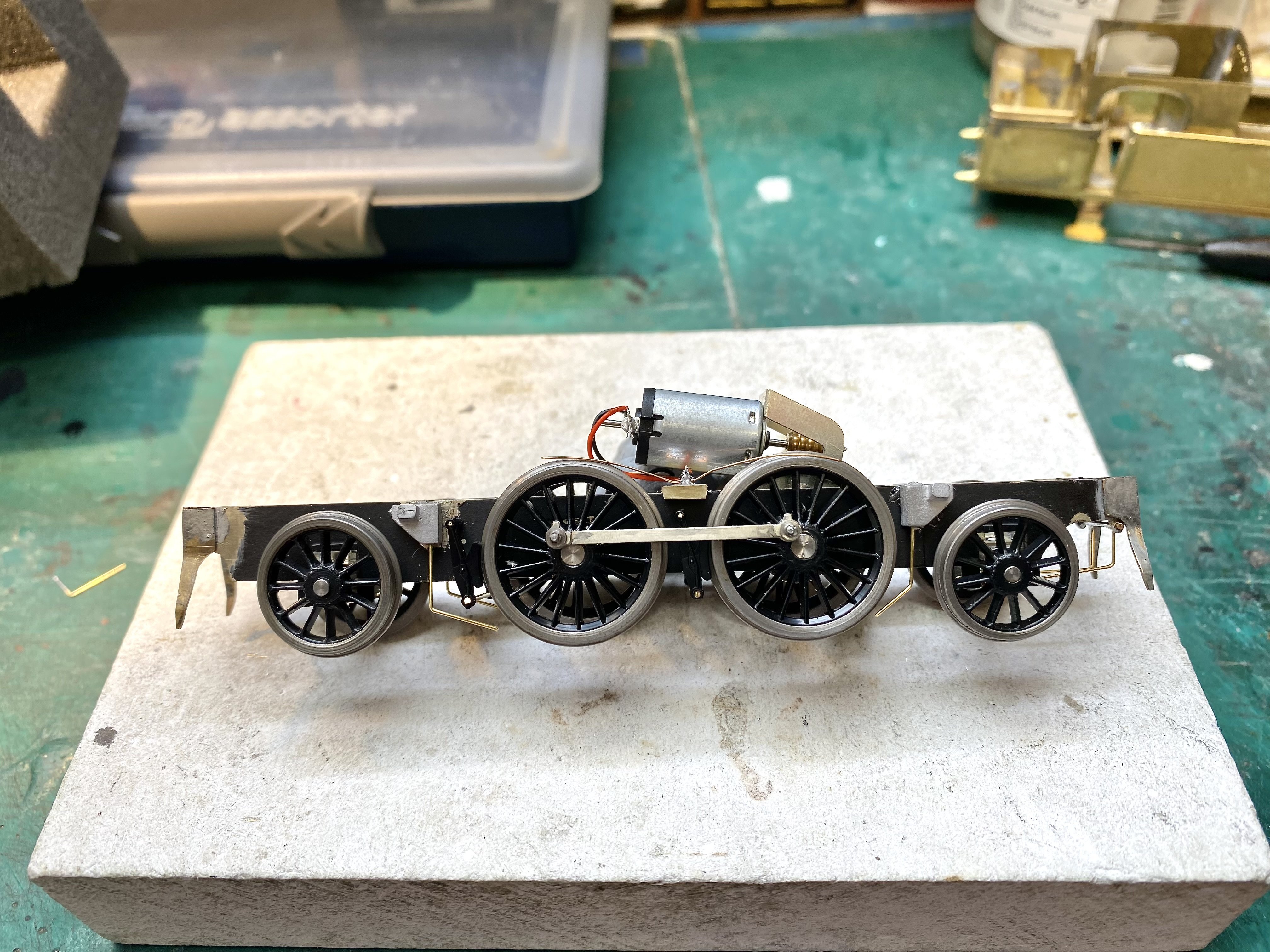
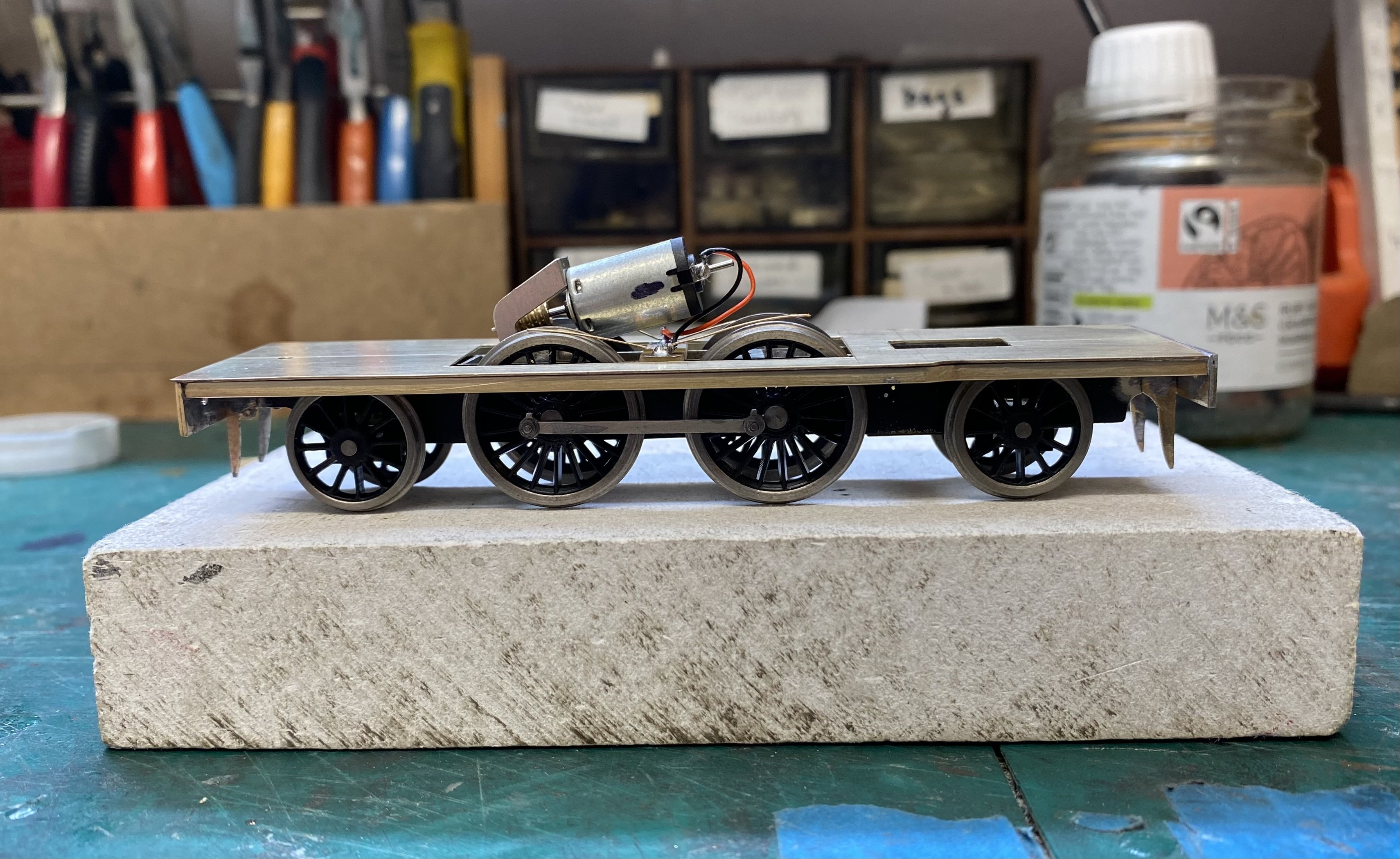
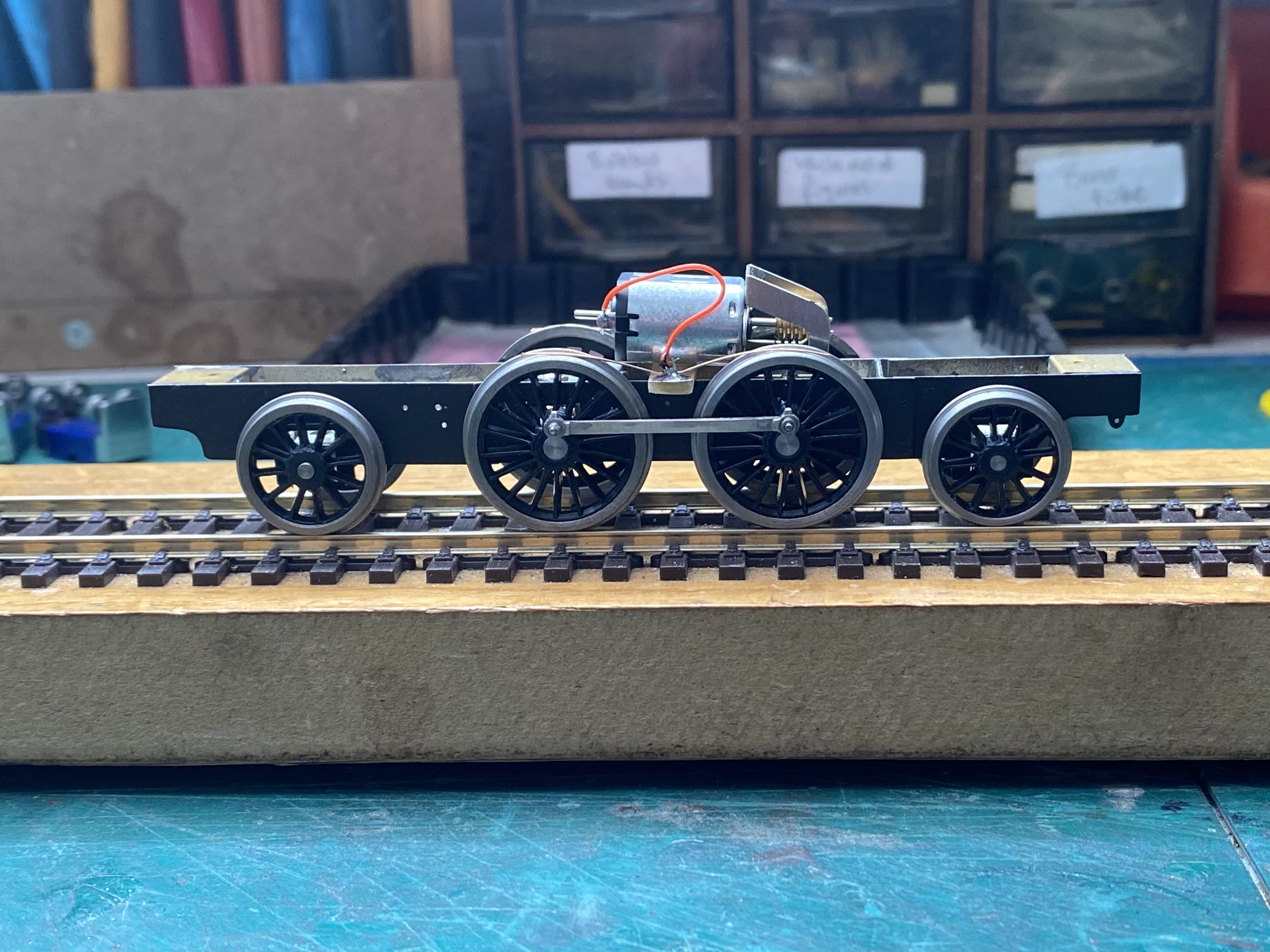
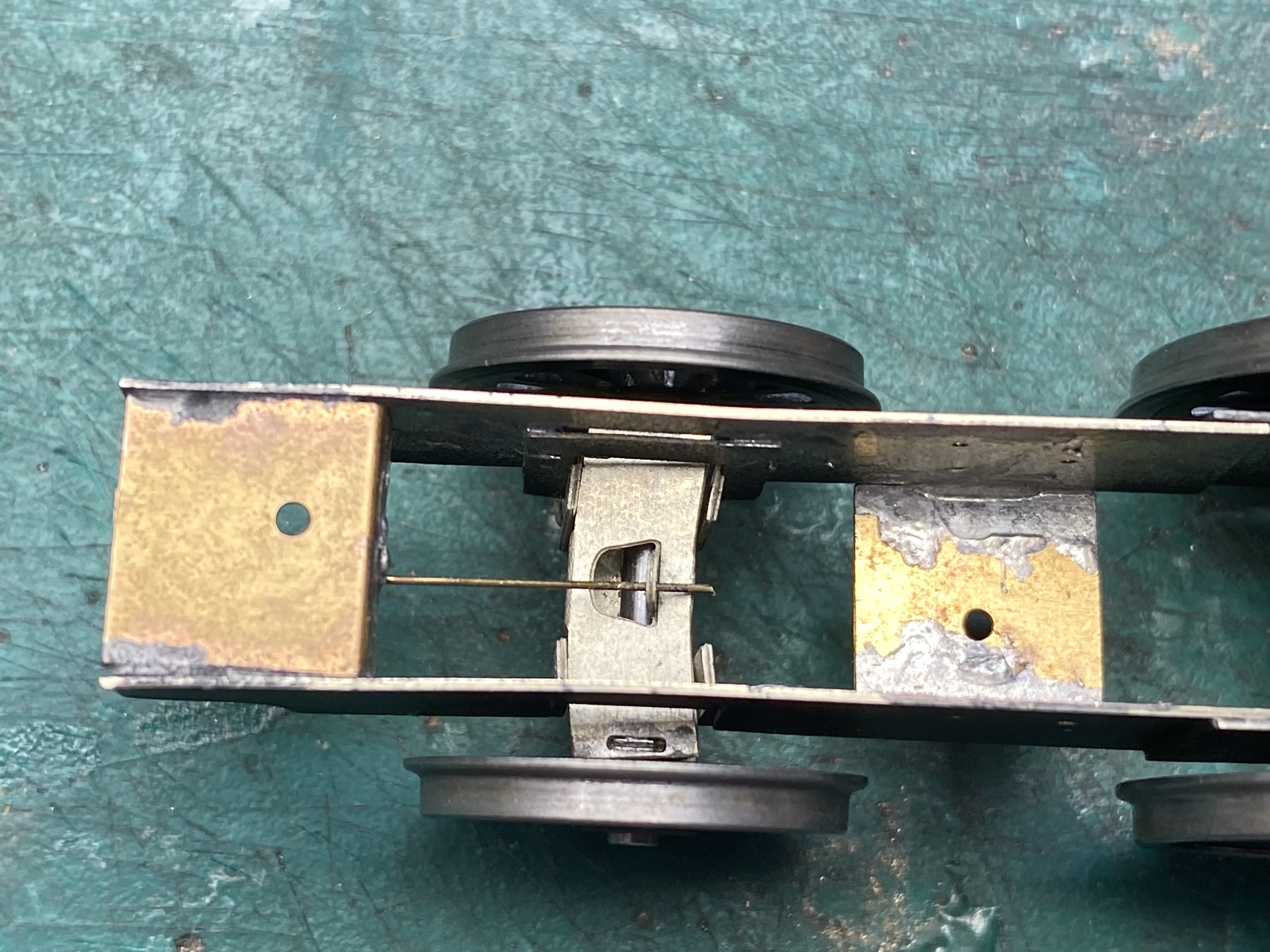
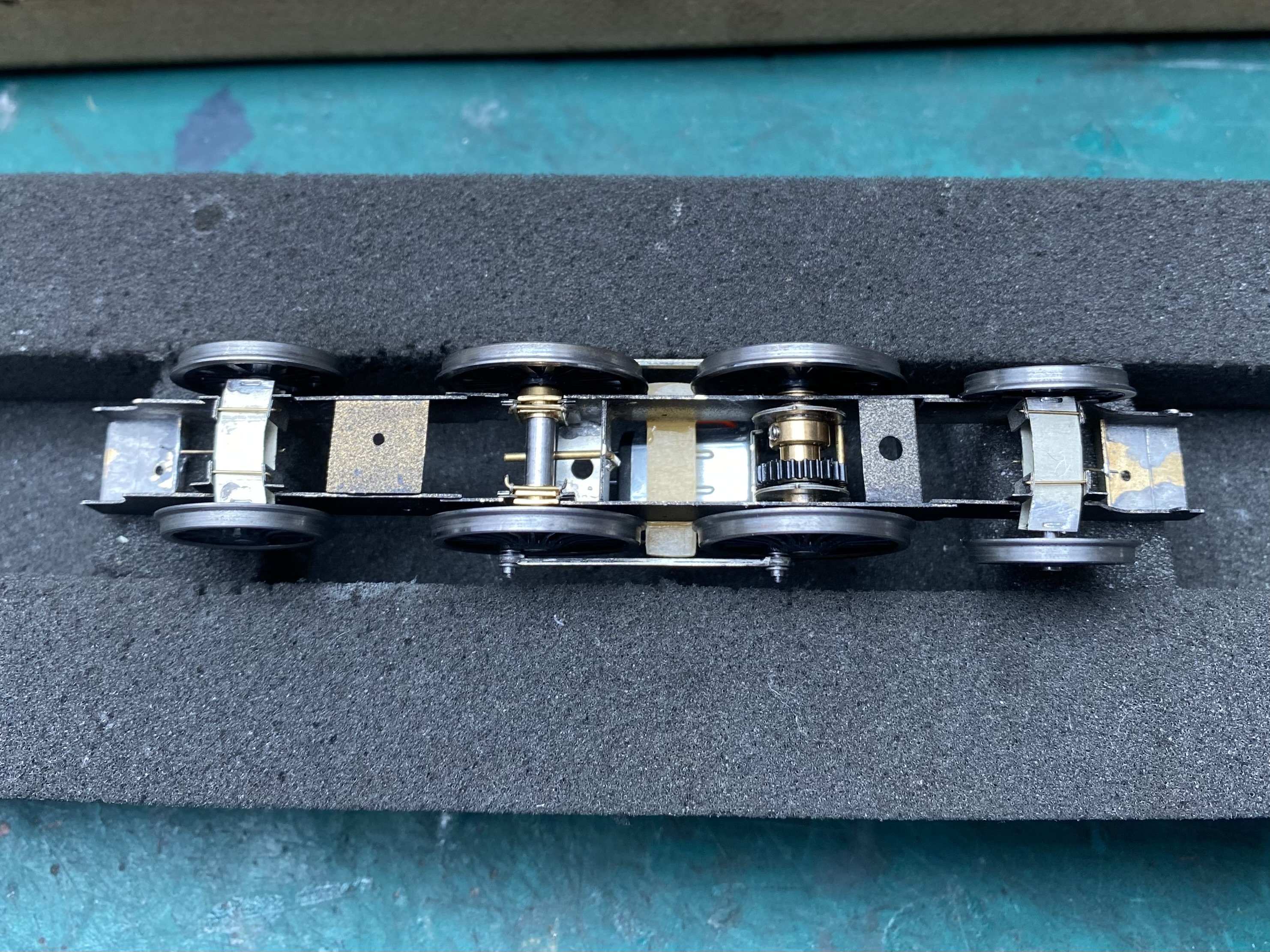
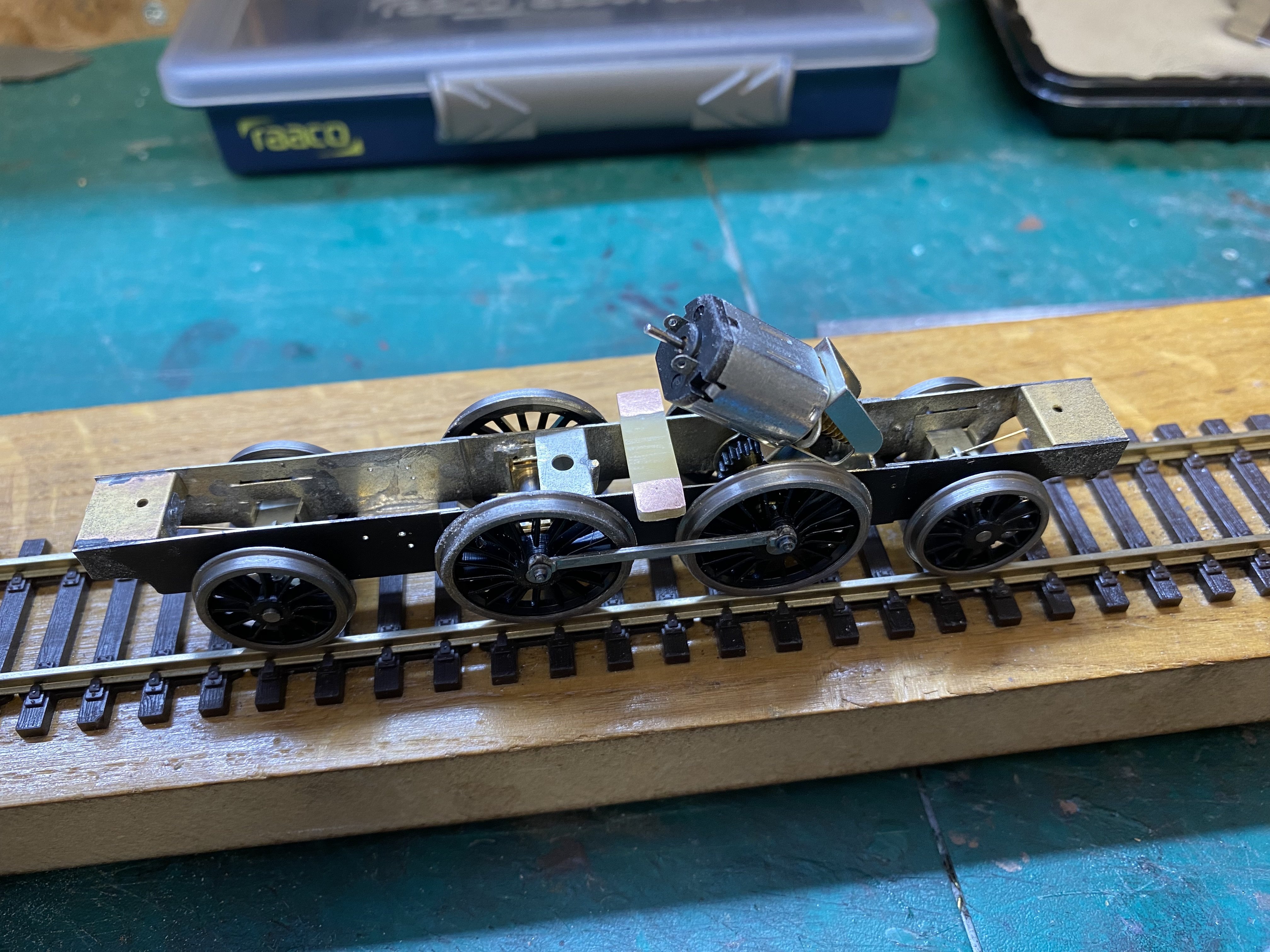
Eight wheels on my wagon now. The London Road Models radial trucks slot into guides soldered to the chassis frames and are prevented from falling out by short lengths of brass wire underneath. The trucks slide from side to side in a gentle arc. A length of 0.33mm brass wire soldered to a frame spacer at one end and slotted into a tab in the middle of the radial truck acts to centre it. It also provides some downforce. Pickups on the coupled wheels are 31swg phosphor bronze wire soldered to a bit of gapped PCB epoxied across the frames. A first run through the points on Loughan Quay looks fairly promising. All the wheels are turning in the right direction despite the video evidence. Honest. IMG_0122.MOV It's spinning its driving wheels in places but the addition of some weight and a bit of tweaking of the truck springs should improve things. All in all, it's performing better out of the traps than I expected. I think this might work! Onward and upward Alan
- 613 replies
-
- 10
-
-
-
Absolutely agree. If it works, it's not wrong
-
Meathdane's advice is sound. You will only need one pair of bus wires. Received wisdom suggests that, for reliability, each piece of track should have droppers to the bus wires to avoid relying on rail joiners for connectivity. Received wisdom also says it's wise to keep droppers as short as possible so this will dictate where you route your bus wires. This always involves some compromise but looking at your layout, a horseshoe shape a bit inboard of your inner oval might be a good arrangement. The odd long dropper is neither here nor there, as long as the connections are sound. How are you planning to connect your dropper wires to the track? Good luck with your project, Alan
-
Happy modelling Denis
-
That’s coming along nicely David. There can’t be many examples of model locos being converted then converted back again (unconverted?)