David Holman
-
Posts
4,359 -
Joined
-
Last visited
-
Days Won
117
Content Type
Profiles
Forums
Events
Gallery
Blogs
Store
Community Map
Everything posted by David Holman
-
Eoin's probably the man for this, but tight spots when adding coupling rods are pretty common. Indeed the only time I don't get them is when scratch building a chassis when the rods are used to drill out the axle holes in the frames - hence everything lines up. However, two axles are easier than three and it is probably just as case of reaming the coupling rod holes a little at a time until they turn smoothly.
-
LEDs worth a try, you can get short strips for interiors that only need a simple 12v supply. Have also used LED strip for layout lighting for several years now. Try LED Hut [find them on Google], the service is excellent. The 'cool white' strips I use on Fintonagh seem to work well. They come on a self adhesive roll that can be fixed to the front pelmet, plus they can also be put in extruded aluminium strip to go over the back of the layout.
-
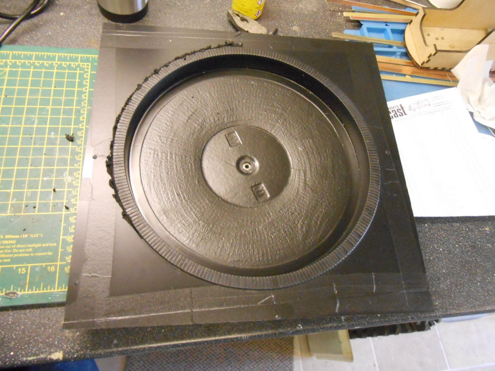
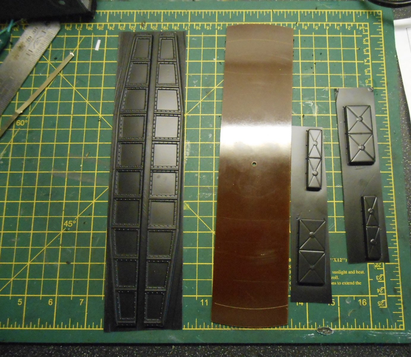
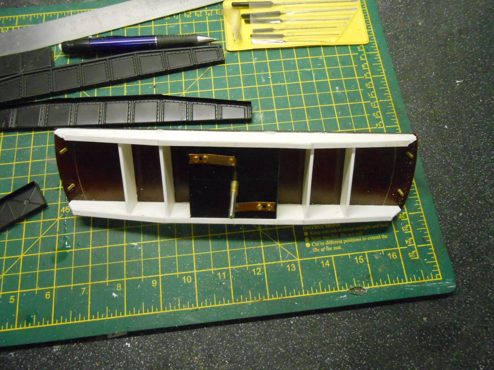
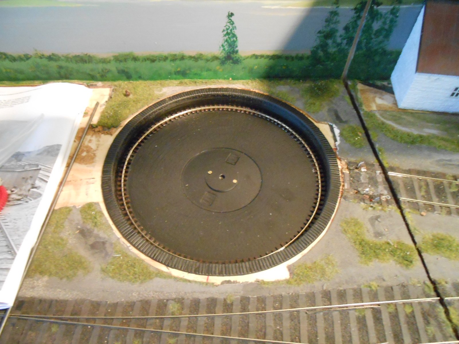
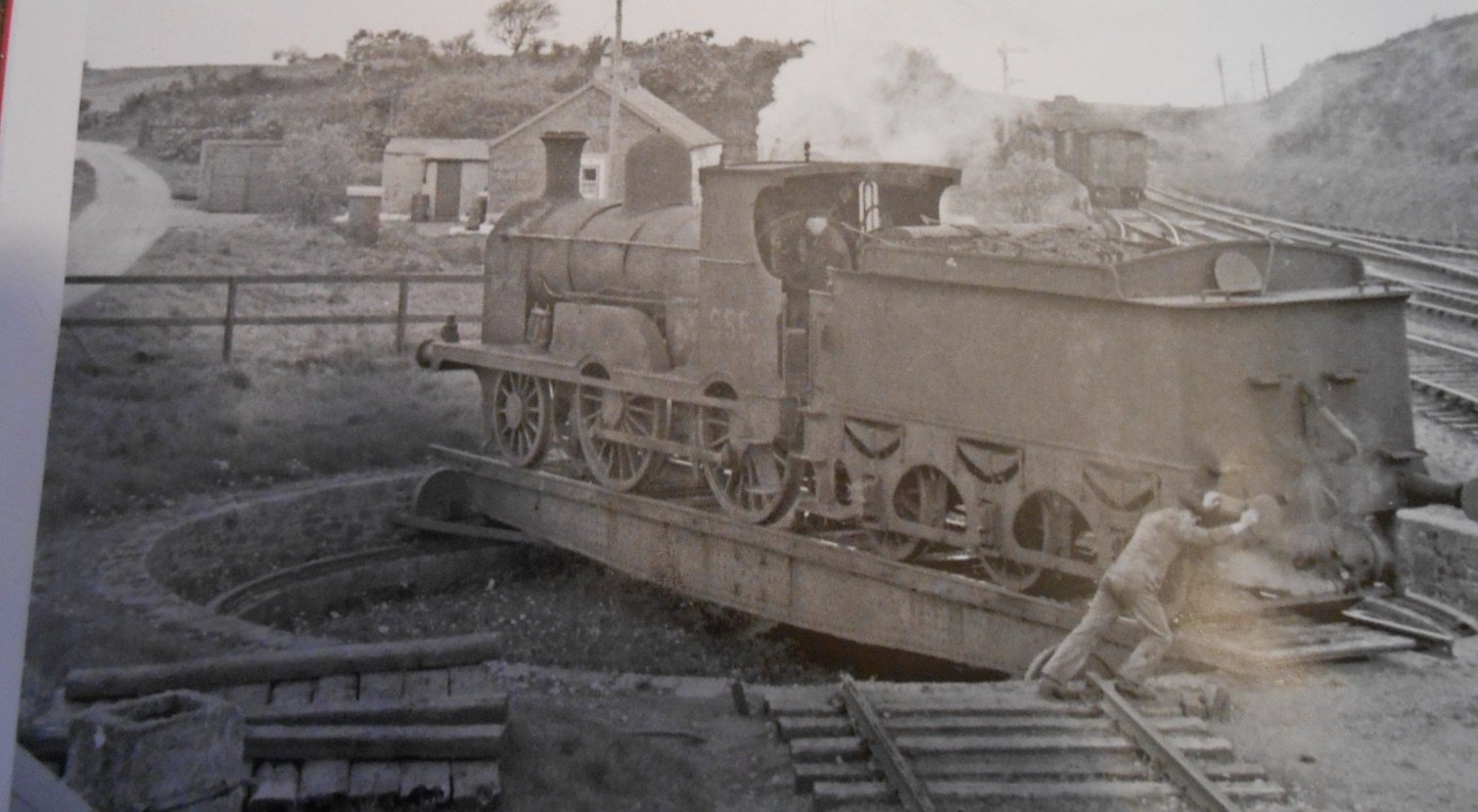
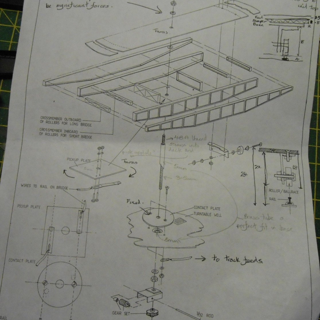
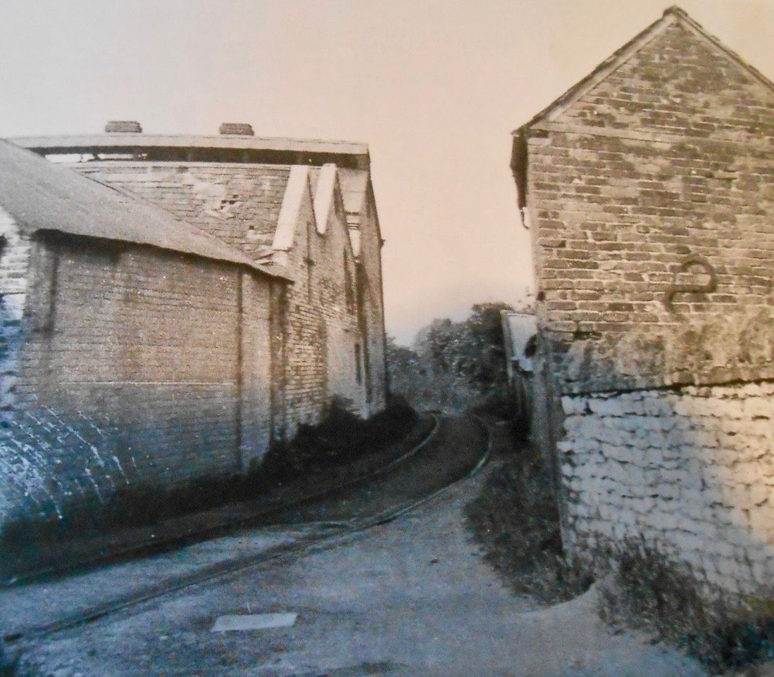
New Turntable Argna Town's turntable was a much breathed on [and sworn at] Dapol/Airfix kit, which cost me the princely sum of £5. I made it underslung, added a Freezinghall Models hand cranked turning mechanism [essentially some bits of Meccano] and it generally worked well for over 30 shows. However, for the Belmullet rebuild I wanted something a bit more robust. I thought I'd found it in the form of Kitwood Models 10.5" laser cut kit. It looks a really good product, though I was told by the proprietor that it might not be strong enough for my 7mm scale locos. Nevertheless, I still wanted to have a go, but have been waiting since May for the kit to be available - something to do with the motors not being ready yet. Indeed, the website currently says 'available September'. Hmm... However, at the Uckfield show last weekend, I suddenly remembered that South Eastern Finecast do a turntable kit and a chat with them on their stand quickly found they did indeed have one for sale. Intended as a replacement for the Dapol/Airfix kit, you can even use the latter's deck parts if you want, while the base [made from a strong looking single black plastic moulding fits exactly the same sized hole as the Dapol/Airfix one. This last fact became a bit of a no brainer, so I shelled out £50 there and then for the kit. The first job was to cut away the surrounding plastic, to leave the circular well which then dropped neatly into place. The rim of the well has brick/stonework moulded on, while the base has a small ball bearing moulded in the centre to take the pivot. The deck is a pice of 2mm thick paxolin, while a range of while metal castings make up things like spacers, bearing wheels and so on. Electrical pick up for the track comes from phosphor bronze wiper pickups touching brass screws in the base. The deck girders are a bit disappointing though, being flimsy vacuum mouldings. I therefore decided to make a new set of girders from 80 thou [2mm] plastic sheet. This has been glued to the deck with 5 minute epoxy, making a strong, rigid structure, albeit as yet undetailed. It will eventually be modelled on the one at the junction for the Ballahagadereen brach [see picture]. The decking girders are intended to run on flangeless, white metal wheel castings, but in the interests of smooth running, I will replace these with miniature ball bearings. The 'track' they run on is cut from a length of Peco Code 75 flat bottomed track. I simply cut it down the middle with strong scissors and then using Pi x diameter got the right length of 81cm. The single rail and sleepers sit neatly against the wall of the well and is held in place with impact adhesive. So far, so good. However, I am currently having problems getting the deck to rotate smoothly, as the paxolin is slightly too big for the well and needs filing back a little. I am also suspicious of the instructions, which suggest using Romford 40:1 gears and 3/32" rod for a hand cranked mechanism. This seems far too flimsy for my 7mm scale locos, so am hoping to use the Freezinghall mechanism again. A further problem is there is scant information in the instructions about how the deck girders are to be fixed to the central pivot. The latter is 4BA studding, with just a nut to hold it to the deck. As far as I can see, there is zero chance of that working, so am hoping that a combination of 24 hour Aradite and Loctite 630 jointing compound in the threads [top and bottom, will do the trick. Will certainly be interested to hear of any other ideas & the final picture might help as it is the exploded diagram of the whole kit.

-
Always a good feeling to know the chassis of a loco kit is going well!
-
Like how the aerial view shows the geography of the scene. Am sure the depth of it is also why it works well. In 7mm scale I'd need about five feet to do that!
-
Great to see general pics of the layout, not surprised IRM wanted to show their locos on it. A fine combination! As for the Deltic, growing up on the East coast main line at Newark, saw all of them, many times, in my spotting days and it was always a treat going to/from college in London to have a Deltic instead of the ubiquitous 47s. Most memorable run was on the Aberdeen mail out of Kings Cross. Loaded to 15 bogies, around 500 tons, it did Grantham to Newark (14 miles or so), in just over 12 minutes, start to stop. The howl of the twin engines going through Peascliffe tunnel from the first coach (window down of course!), was incredible. Was convinced it wasn't going to stop at Newark and I'd have to find my way back from Retford, but a very late brake application got me home. It was a fine piece of driving and the loco really must have been on the limit. Regularly timed them at over 100mph and seem to recall up to 110 wasn't unusual in Railway Magazine reports.
-
Nice one! The addition of a front view blocker works really well in the pictures and puts the whole scene in its proper context. In some ways a bold move to put the focus of the diorama further back, but for me it balances the scene and frames it so the viewer is on the platform, looking in and everything appears bigger too.
-
For the Irish scene, you will eventually be stymied once you get to a 2-10-0!
-
For me, nothing says Irish railways better than 21mm or 36.75mm track. The Peco code 75 certainly looks so much better than code 100 though, especially if you can keep to a low viewing angle. See Patrick's layout thread for that. However, would still say doing 21mm is worth a try. Plain track is easy to make using C&L components, while points could be custom made by the likes of Marcway, or again have a go yourself with C&L. The only thing you'd need to find/have made is a suitable roller gauge. 21mm is not about P4 either, finescale 00 clearances (one mm flange ways) will be fine. One point and a couple of lengths of plain track should only take a couple of hours using C&L parts, with no soldering required either. Worth thinking about.
-
Certainly looks the part.
-
A GNRI 2-4-2T? Nice prototype and what looks like a fairly simple chassis. Am guessing the leading and trailing wheels will require a fair bit of sideplay, though two coupled axles should be easier than three. A logical progression from a single, methinks! Have built several Alphagraphix Tyrconnel kits and though fairly basic, they seem to go together nicely, so will look forward to seeing progress.
-
That is going to be a very impressive rake.
-
In this month's Continental Modeller, there is an article doing a cut and shut with a Britannia to create a freelance South African Pacific. All about character and this model has plenty and even if it is freelance, it really looks the part. The large scale WW1 trench layout also features.
-
All that is needed for curved edges is some thicker microstrip, say 80 or 100 thou, welded to the inside seams. This means you can then file and sand radiuses edges and corners with any fear of making holes in the sides. There again, the were square edged tanks, so either will do.
-
Some video footage of Fintonagh at the recent EuroEx show in Birmingham. Fintonagh is at about 16-17 minutes, but there is some nice footage of the other layouts, including the large scale WW1 trenches depot.
- 266 replies
-
- 11
-

-
Just goes to show what you can learn from being a railway modeller. Looks like I have some remedial work to do on my tank now!
-
There was an article in Model Railway Journal, by John Birkett-Smith last year, where the back scenes were in layers - a profiled piece of MDF fixed direct to the baseboard, then a separate skyboard, set a few mm out, behind it. The effect looked really good. On both Arigna and Fintonagh, I use quick mounting plates to hang pelmets, fascias etc and they work very well.
-
Not just any old crossing vee! Lovely touch and authentic details like this really bring a model to life.
-
Coming on nicely.
-
Thanks guys, though no peat fire ash? Sifted garden soil works well too, apparently. We used to have a multifuel heater, before gas arrived in our street and I used phurnacite ash quite a bit for ballast. Gives off a pretty sulphurous smell when mixed with dilute PVA though! Several of our neighbours still burn the stuff, so I may well go calling.
-
Another thought, check the balance of the loco - does it pivot on the centre axle? If not, you'll need to add more weight to the other end.
-
Further to the above, just back from a walk in a local country park, where the paths are made of crushed stone, most of which was around 1-2cm across. In 7mm/1:43 scale, that equate to around 0.5mm, so about 0.3mm in 00. Woodlands coarse cinders and ballast is around 1-2 mm in size, representing something around 7-15cm in real life. Makes you think and certainly wouldn't want to run over a 10cm rock in my car.
-
Modelling clay, Polyfilla, etc are what I have in mind, keeping additional scatter material to a minimum. Depends on the scene being depicted of course, but sometimes get the feeling that what at best should be fist sized pieces, ends up as almost boulder sized ones. In 7mm scale, even a 1mm diameter piece of grit represents a two inch diameter stone, when most yards would have their largest bits only half that at best. Woodlands Scenics fine ballasts (crushed coconut shell, I believe) are about 0.5mm or so, and nominally sold for N gauge. Many 4mm scale modellers use the fine stuff though and I've always been happy with their fine ash in 7mm scale. On the same principles, it is arguable that printed papers are all you need for brickwork, as mortar lines would have little, if any indentation when scaled down 72, or even 43 times, while the same applies to tarmac road surfaces - talc on paint, or 400 grit wet n dry is enough in 7mm scale for me. However, scaling everything down ad infinitum doesn't always work and a bit of over emphasis can help fool the eye into thinking something is right, when it isn't and indeed vice versa, as per not putting in track fixings at all. Where is this rambling heading? Not sure, except maybe it is simply a case of beauty is in the eye of the beholder, though as my art teacher always said: 'Paint what you see, not what you think', so maybe careful observation remains the key.
-
Cleanliness comes well before godliness in all aspects of model railway running. Is the track clean? Are the wheels clean? Try putting two wires direct to the wheels, rather than the track, to see if the pick ups (some or all) are working. Try taking the body off, if you can, and put wires directly to the motor. It is all about trying to eliminate what might be wrong, until you find the thing that is. Good hunting, and keep us appraised.
-
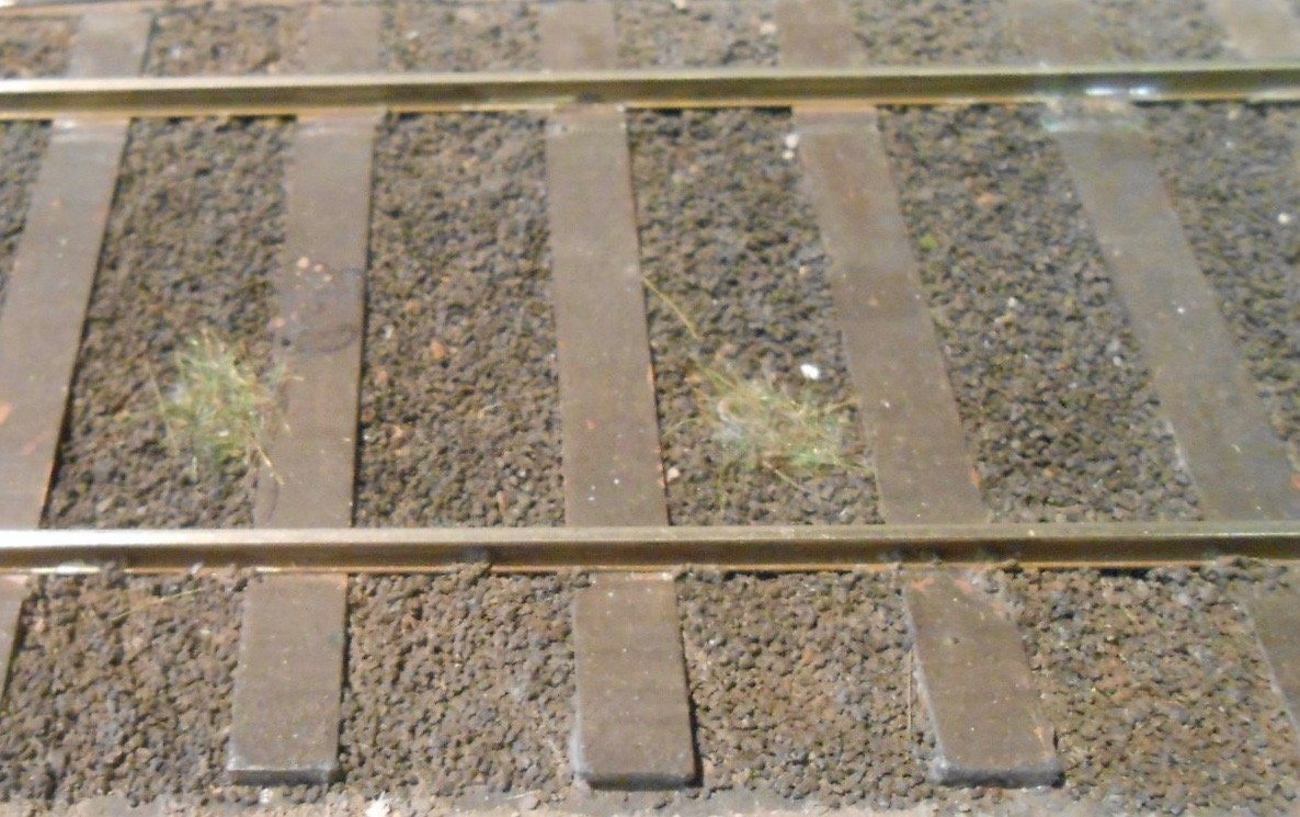
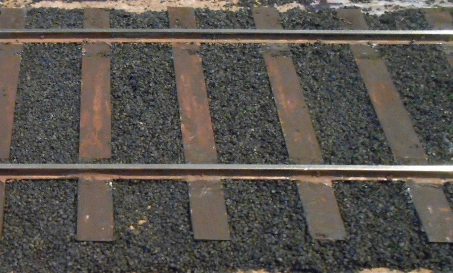
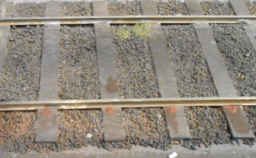
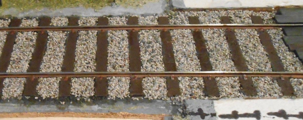
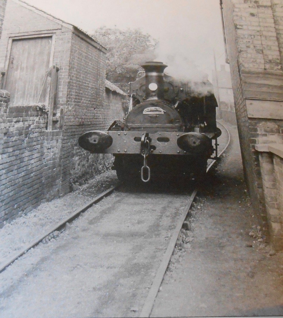
Track and ballast As promised, a look at treatment of track, old and new. The third picture shows original Arigna track, heavily weathered and toned down with talc and weathering powders, but without any cosmetic rail fixings. The second picture is new track, still needing more coats of paint on rails and sleepers and with no weathering or toning down of the Woodlands fine ash ballast. Note how dark the latter is and what a difference a dusting of talc makes to all the colours. The talc was never fixed and has survived without problems for over thirty shows, including being vacuumed before each one. The other two show various attempts at representing the FB rail fixings. Slivers of micro strip are used at the right hand end of picture four, while the other 'fixings' are simply blobs of acrylic paint put on with either a screwdriver or cocktail stick. Both need some weathering or further paint/both, but it is views of the general impression I'm interested in. Arigna got away without any rail fixings, but I'm thinking Belmullet would benefit from a general impression of them, but without going to the trouble of drilling and fitting up to 3000 Peco track pins. Yes really. The actual fixings were a thin plate held down with a bolt & nut. Note this is 7mm scale, 36.75mm gauge track, using copper clad sleepers and Code 100 flat bottommed rail. The granite ballast is also from Woodlands, being three different tones of their fine grade again. So far, am only thinking of doing the short stretch exiting the layout into the fiddle yard, though may yet do a bit more of the 'mainline' into the station platform, not least because when the layout is operated in early 1900s guise, the ballast would still have been fairly clean - though ash was used extensively in station sidings. The final two pictures are a couple of my favourites. The first is at Leiston in Suffolk and shows the siding to Garrett's engineering works, while the second is the approach to Wantage Town station. It is this effect that I'm looking to replicate on the new harbour branch on Belmullet. To my eyes, it is very noticeable how fine the ash ballast looks - even finer than Woodlands, so will be trying a mixture of talc, polyfilla and chinchilla dust to try and replicate the texture. Eventually...