David Holman
-
Posts
4,359 -
Joined
-
Last visited
-
Days Won
117
Content Type
Profiles
Forums
Events
Gallery
Blogs
Everything posted by David Holman
-
Lovely details, which of course is exactly what doing a diorama is all about.
-
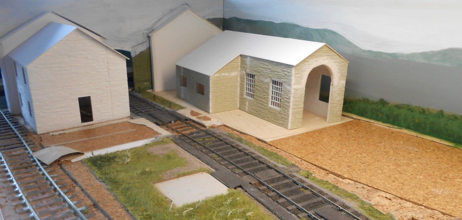
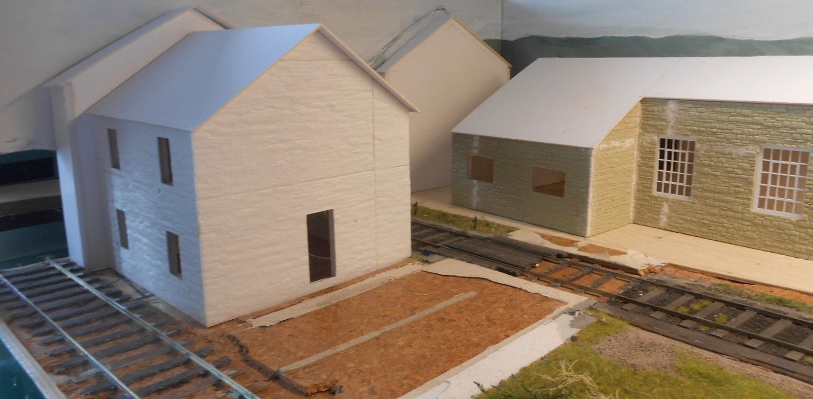
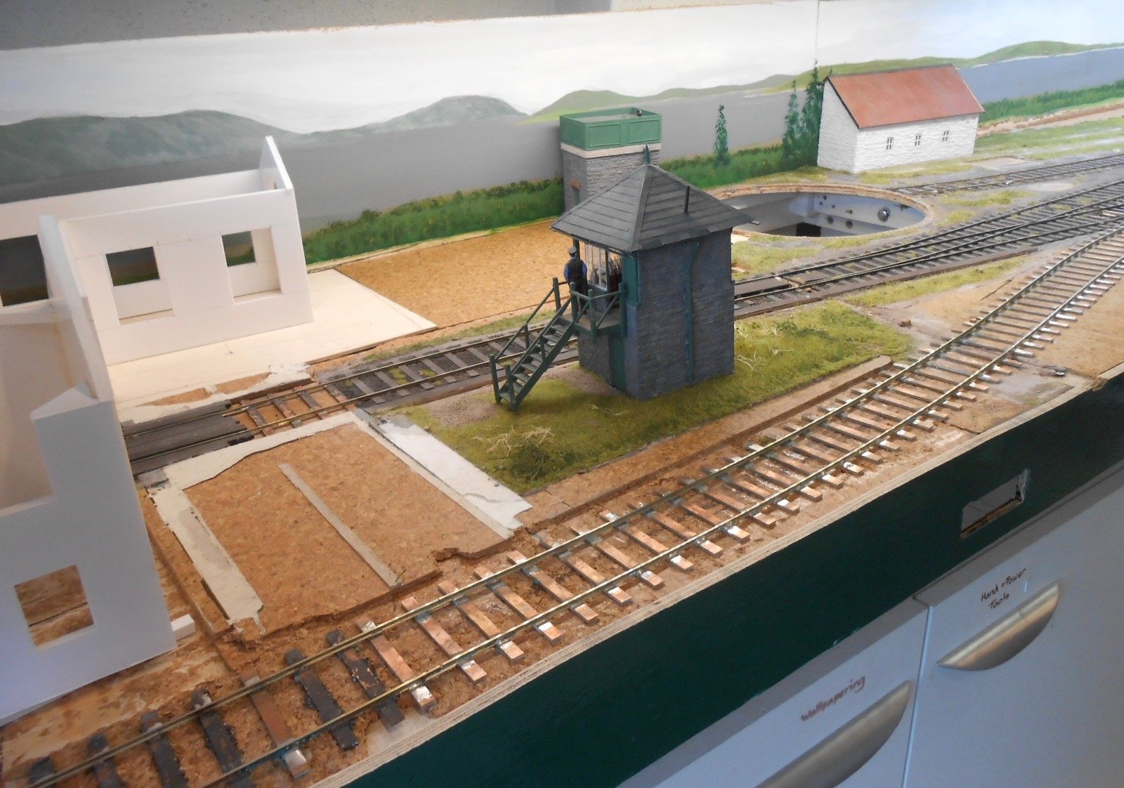
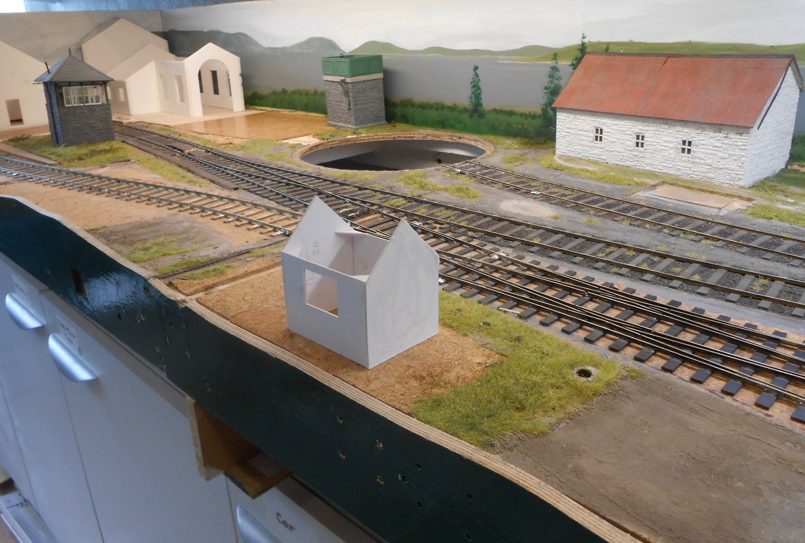
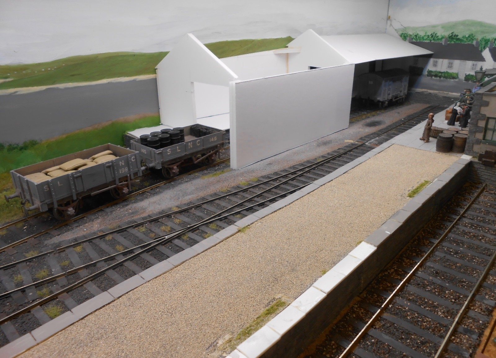
More visualising Having got a fair way with the loco shed, I next wanted to sort out how it will 'sit' in the lefthand, rear corner of the layout. In an ideal world, both the landscape and separate, sky, back scene boards would be curved at about 10-15cm radius, to avoid a right angled corner in the scenery. However, this is not practical [at either end], so a bit of subterfuge is required. What I'm doing is to use a 'flat' - essentially a 1 cm deep gable end of what is meant to be part of a whisky distillery. This is angled slightly, so that when viewed, the lack of depth won't be apparent. In addition, I've painted another section of this building on the back scene, but at right angles to the 'flat'. Between the signal box and the white building [which is the admin section of the distillery], there will be a scots pine, about 20cm high, which I'm hoping will help to hide some of the above too - including the hole in the sky, where the main line exits to the fiddle yard. The Belmullet Distillery - home of Blacksod Bay Whisky - will be a useful source of traffic to the railway, with not just grain in & booze out, but also peat to fire the boilers. There are of course peat workings nearby and this also gives me the excuse to build and run two or three of those splendid 'peat wagons', made from converted WL&W six wheel coaches, by boarding up the windows & removing the roofs.

-
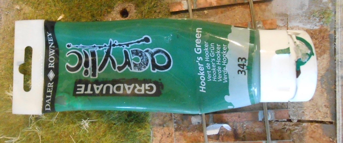
Hooker's Green. Not a special liniment for the big boys [and girls] of the front row, but a very useful dark green, which I use a lot for scenic backgrounds. Comes in a variety of mediums - oil, water & acrylic. On the Belmullet backscene it was mixed with ultramarine [and lots of white] for the distant landscapes and yellow ochre, burnt sienna & again, more white for the nearer landscape.
-
Nice. Very nice in fact. That track just looks so right - no doubt because it is!
-
The purchase option is there, DC. Marcway will do custom pointwork in 4mm and 7mm for a fee, usually about 50% above standard gauge, which actually not much more than Peco. Coaches, wagons and diesels not much of a problem, though steam outline conversions of RTR more difficult I think.
-
Beautiful work!
-
Presumably, you don't take it with you on the bus, or do it while watching TV?! Rather fabulous though and so important to the overall scene.
-
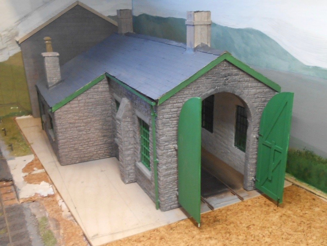
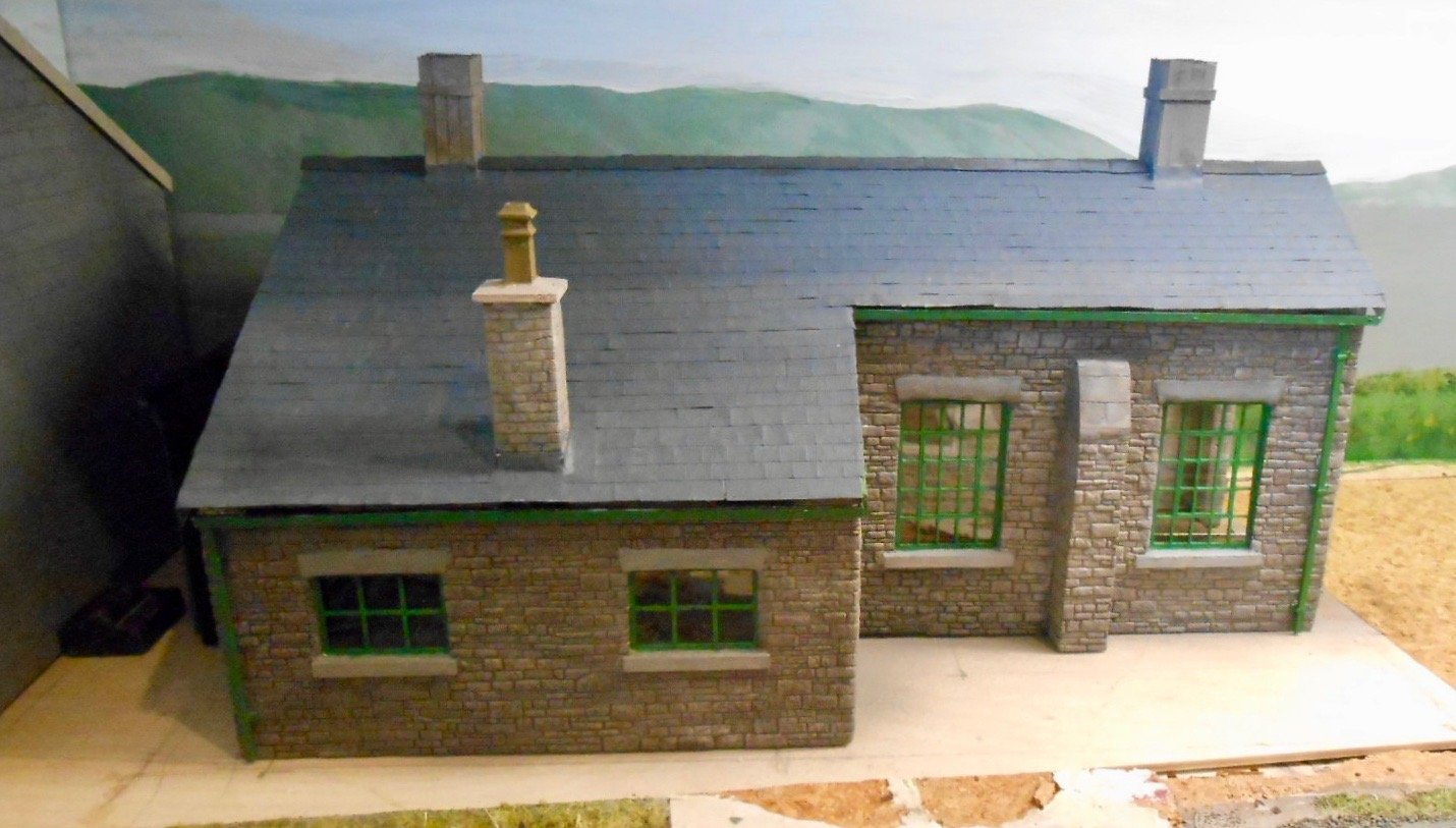
Details and painting It has taken a fair bit of work to get this far. The list includes: Filling in gaps where the stonework sheets are joined, both inside and out, plus at the corners Tidying and levelling the shed floor, then scribing in the setts/bricks Painting the window frames, then glazing them when dry Painting the interior walls white, then toning them down with weathering powders Making and fitting the two front doors Adding the false roof, then putting on strips of slates made from cartridge paper nicked every scale foot. Downpipes, made from 2mm square plastic strip Two smoke chimneys on the roof ridge, plus cap and pot for the chimney [whitemetal casting] in the workshop area. Plus painting the exterior stonework All the painting has been done with cheap, art shop acrylics. I used white, black and ultramarine for the slates, with the same colours, plus brown for the stone walls. The doors, windows, guttering etc are a mix of hooker's green and yellow ochre. The model still needs final detailing, not least some weathering, while ground cover will be built up on the base, before it is eventually screwed to the actual baseboard. Have yet to decide whether to add any interior lighting. Lurking behind the shed is a low relief building that will form part of the distillery. Am hoping to blend it in with the back scene like I've done with some of the Fintonagh buildings, with probably something like a scot's pine near the signal box to hide the inevitable liberties needed with the perspective.
-
Sounds fabulous. While you may not yet have space for a layout, there sounds like plenty of opportunities to create a fair few pieces of the jigsaw puzzle for when you do. And, dare I say, it would be really interesting to see and read about how you get on with them too.
-
Many thanks, Mike. I somehow read it as T-scale, so was in awe of so much stock that small! Nevertheless, N gauge is still going some and for a project this size and am sure you are right going for overall impressions ahead of complete fidelity. At the usual range of about a metre,am sure it all blends together beautifully. Thanks again.
-
Bearing in mind how tiny all this stuff is, it would be fascinating to hear more about where all the stock comes from - bodywork, mechanisms, couplings and so on.
-
Lovely stuff!
-
Further to the above, remember Roy writing about how his locos had little if any springing, but lots of weight, pick ups on every wheel and big, beefy motor gearboxes, with robust frames and bearings too. Trains ran long distances, so lightweight chassis and mechanisms soon wore out. We found the same thing at my local club, where we are building a 7mm scale tailchaser. The circle bit is 4m in diameter, so one circuit is at least 13 metres or forty feet, while the 16 foot straight sections take that up to over seventy - a scale half mile. Hook a loco up to a reasonable train and you need to be careful. Even five minutes circling round is the equivalent of a whole day's running on a terminus - fiddle yard layout. As several people have found to their cost. For example, a big V2 with just a Mashima motor gearbox would found to be running very hot and subsequently required a much more robust set up. Can't speak for many RTR models, though there are well known issues with early Heljan diesels - heavy, but prone to gear damage. The moral is go carefully when letting trains circulate. Check them every couple of laps for signs of over overheating and likewise for wear if they get used a lot.
-
In this month's Railway Bylines. Eight pages, with some fine photos, including a particularly good one of G2 655 on Kilfree turntable.
- 1 reply
-
- 2
-

-
They were in Model Railway Journal, Joe, but as to which numbers, I have no idea other than they were fairly early
-
Signals are fragile things at the best of times and very prone to damage even on a permanent layout. My triple signal on Arigna/Belmullet has survived 30+ shows mainly because it is removable for transport and storage, plus the posts and brackets are whitemetal, with everything else in brass. Being 7mm scale, it is that bit more robust, so goodness knows how the 2mm boys get on. Wizard models do a nice range of signal kits. They look complicated, but the instructions are very good, so might be worth a look.
-
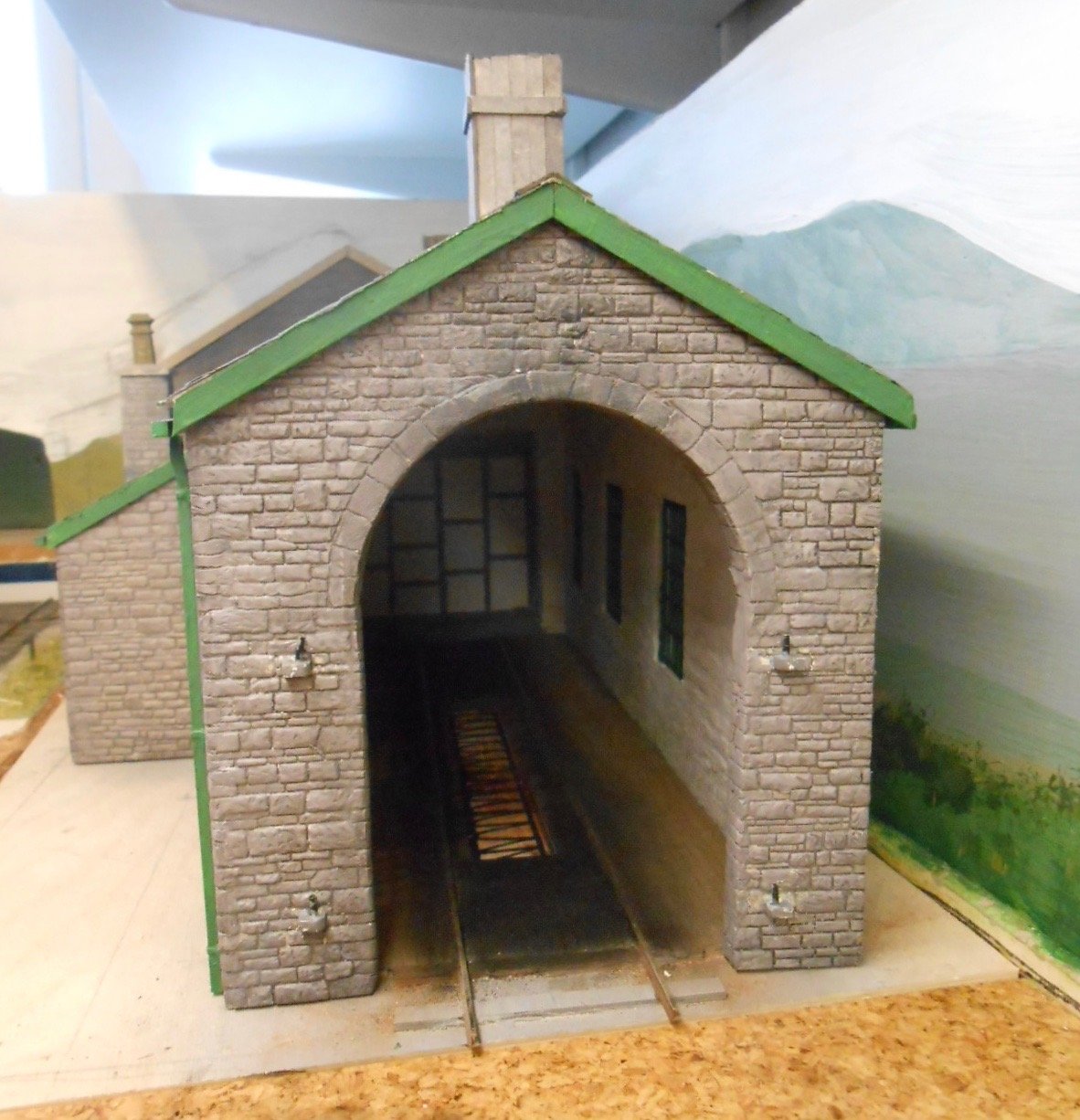
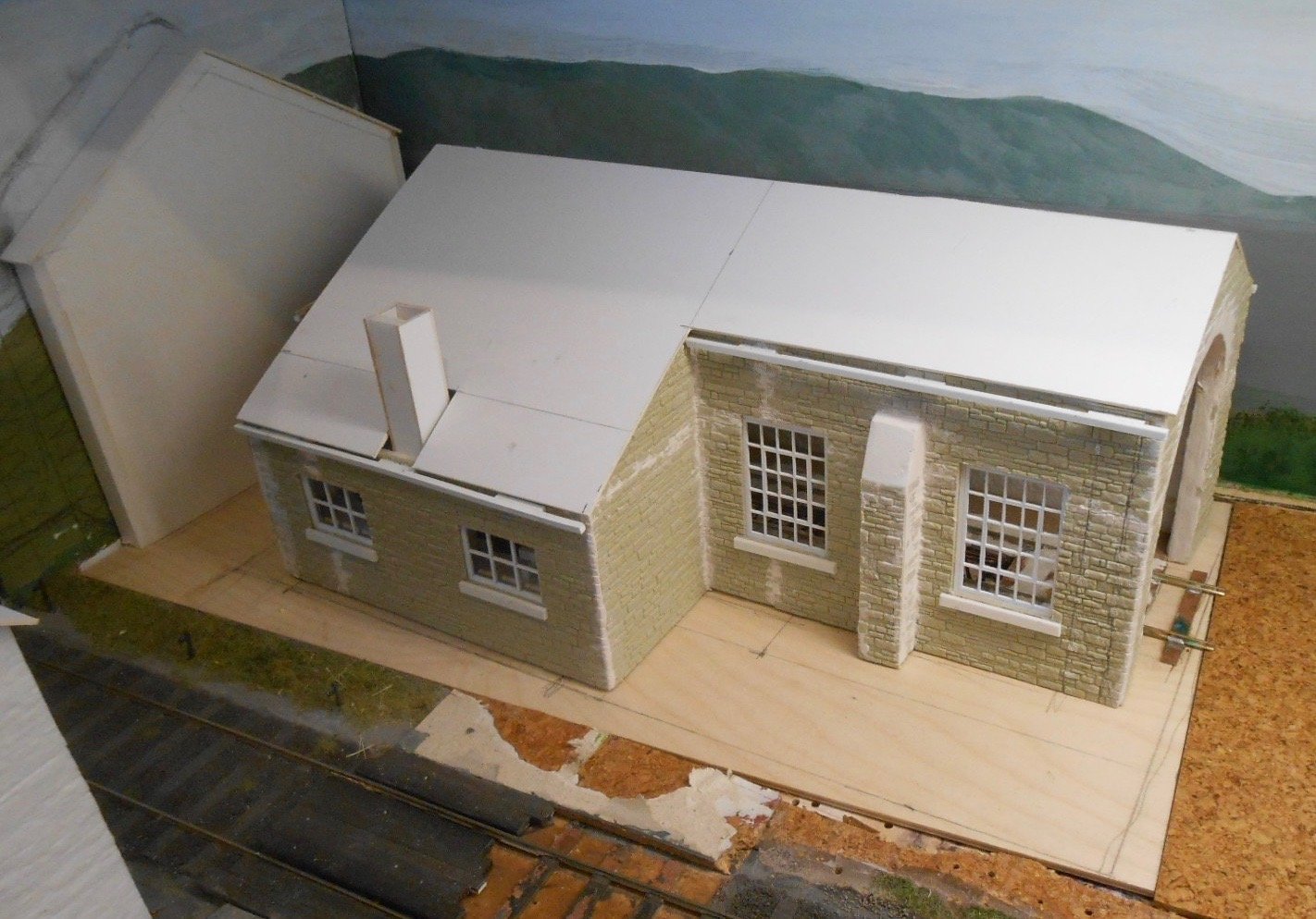
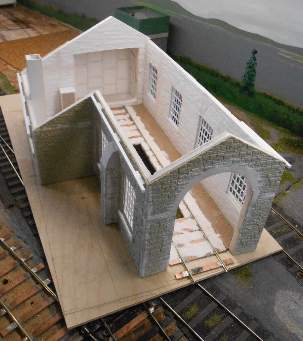
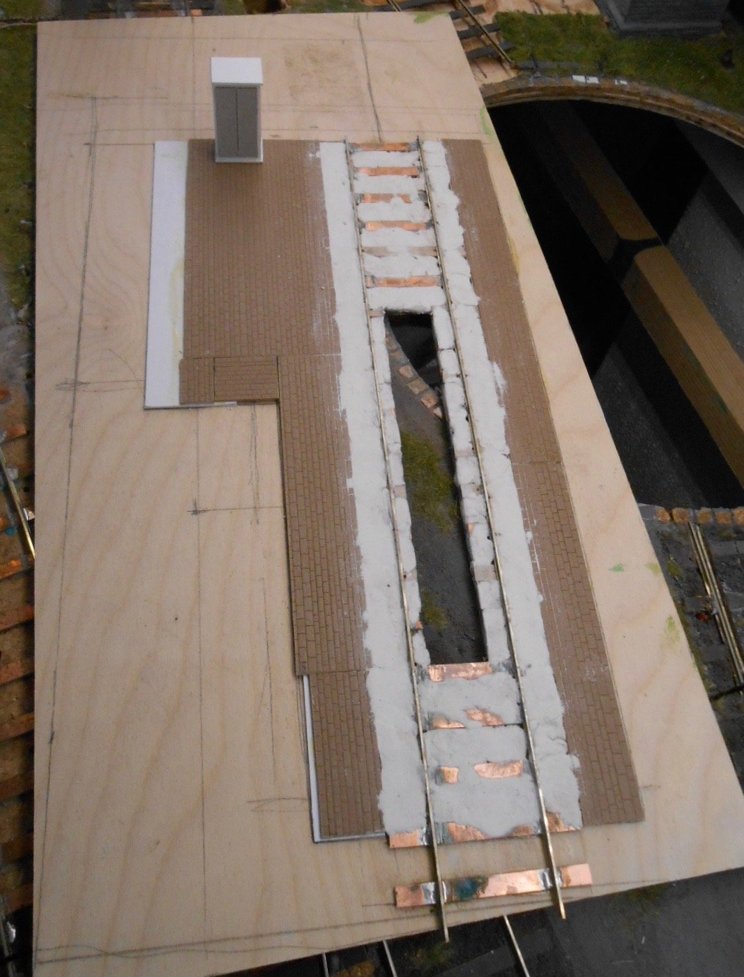
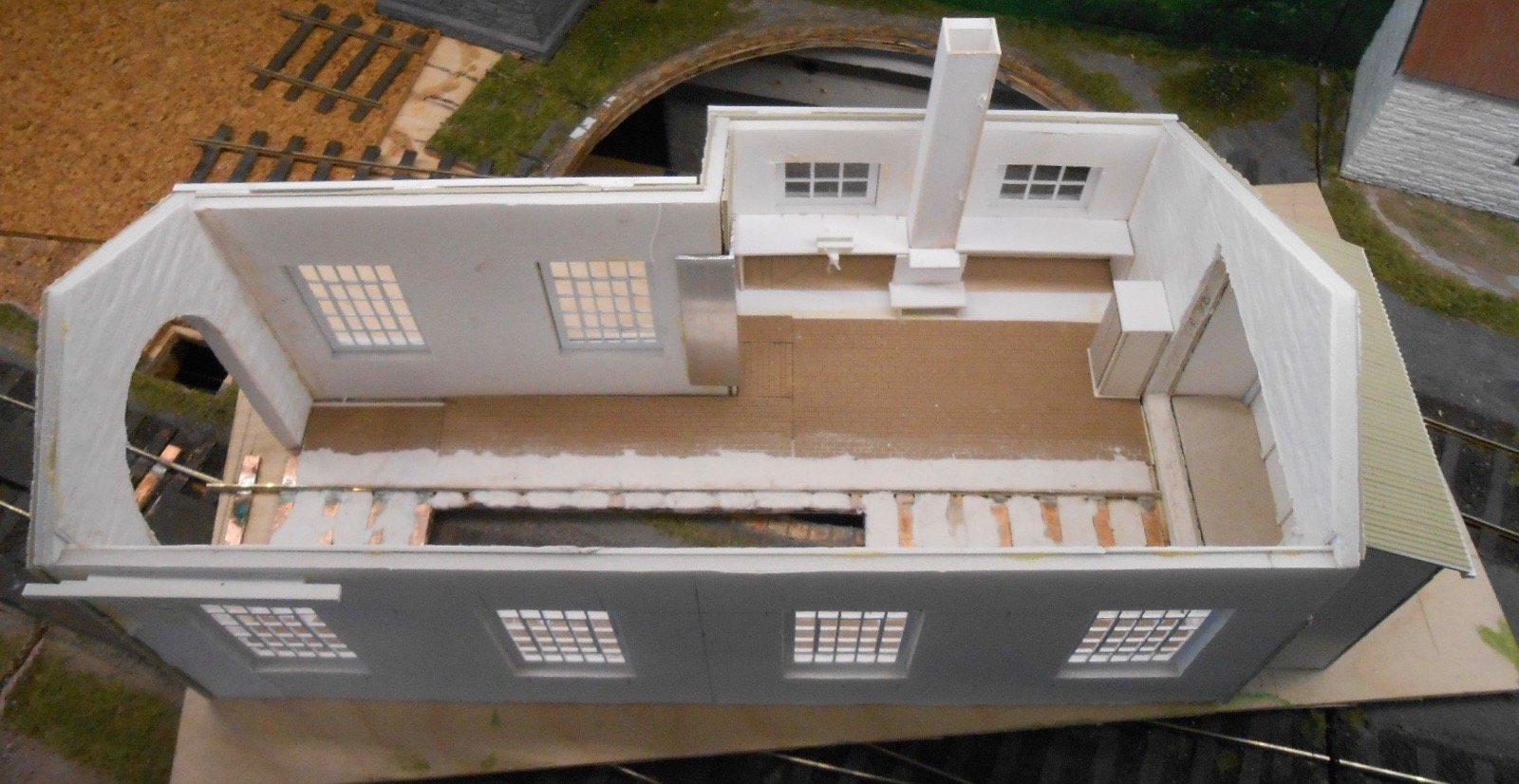
A locoshed for Belmullet Can't believe it is 4 months since I did a workshop post, but everything has been layout orientated of late, so it is time to do something more specific. Anyone who has built a loco shed will tell you they can be awkward things, that are not a little fragile until the roof goes on. This is mainly because the opening for the loco results in weak spots on the two front corners while because they are perforce, single storey affairs, there is nowhere to put any internal bracing either. Experience has taught me that it is useful to build a loco shed on its own subframe, which can then be screwed to the actual baseboard once everything bar ground cover has been completed. I've based the shed for Belmullet on the one at Ballaghadereen, though I've made the workshop section only half the length. This is because I want a second siding coming off the turntable, so I can park a wagon of loco coal [and another for ash], alongside the line leading to the shed itself. This then made for another weak corner, which you might see has been braced with a short piece of aluminium angle. The core of the building is 5mm foam board, which is covered with Wills 'random stone' sheet on the inside and rendered stone sheet from the same source on the inside. The windows are from the York Modelmaking range and very nice they are too - saving a lot of work in the process, plus they only work out at around £1.50 each. Compared to covering the shell in Das clay and scribing the stonework, the Wills sheet is pretty quick too, while it also offers a lot more relief than scribing yourself. The downside is that a lot of filling is required to make the sheets match up, especially at the corners, with subsequent extra scribing too. The base is a piece of 3mm plywood [from Hobbycraft], which nicely matches the height of the cork floor tiles I use as track underlay. I cut a slot out for an inspection pit [which will be deepened by a similar slot in the baseboard itself], then made a length of track from copper clad sleepers and code 100FB rail, as per the rest of the layout. At this point, a couple of errors became apparent. First, the front opening was too narrow for any loco to pass through, and second, the shed itself was too short for any of my tender locos! A bit of robust filing eventually sorted the opening, but the shed length required more thought. At first I considered just lengthing it by adding a new section, but that would have messed up the symmetry of the windows. Instead, I've put an extension on the rear wall of the shed, using Wills corrugated asbestos sheet, as sold for 4mm scale. Indeed, all the Wills sheets are 4mm scale, but they seem ok in 7mm & the asbestos version has bolt heads moulded on as well. Anyway, the story is that, like the Achill Island branch, Belmullet was originally worked with MGW E class 0-6-0Ts, but soon after tender engines arrived, one was driven rather too enthusiastically into the real wall. Realising the need for more space at this point, the engine sized hole was enlarged slightly and a timber framed, wiggly tin extension built. A bit of fun was had with the interior, putting in a little basic detail in the form of a decent sized stove [large enough to do a bit of smithing], a workbench either side [one with a large vice on it], plus a storage cupboard for the loco crews. The flooring has been built up to be level with the tops of the sleepers, using card and more embossed sheet - brick setts this time - filled in with Das clay. On the outside, you can see my method of doing guttering. 2.5mm square plastic strip is used for the gutters themselves & this is projected out from the tops of the walls by additional pieces of the same section. The roof slates, when added, will overlap the gaps you can see at the moment. So there we are so far. I'm hoping that, by the time the shed is finished, a Kitwood Models 10.5" laser cut turntable kit will be available again, as that circular hole in the baseboard really needs filling!
-
Certainly looks the business so far. Another one to watch, methinks.
-
Very subtle = very good indeed. Not easy!
-
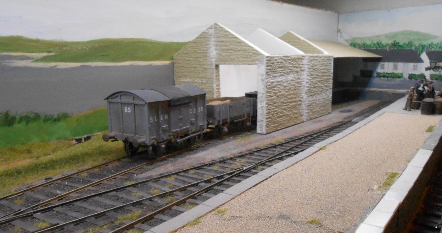
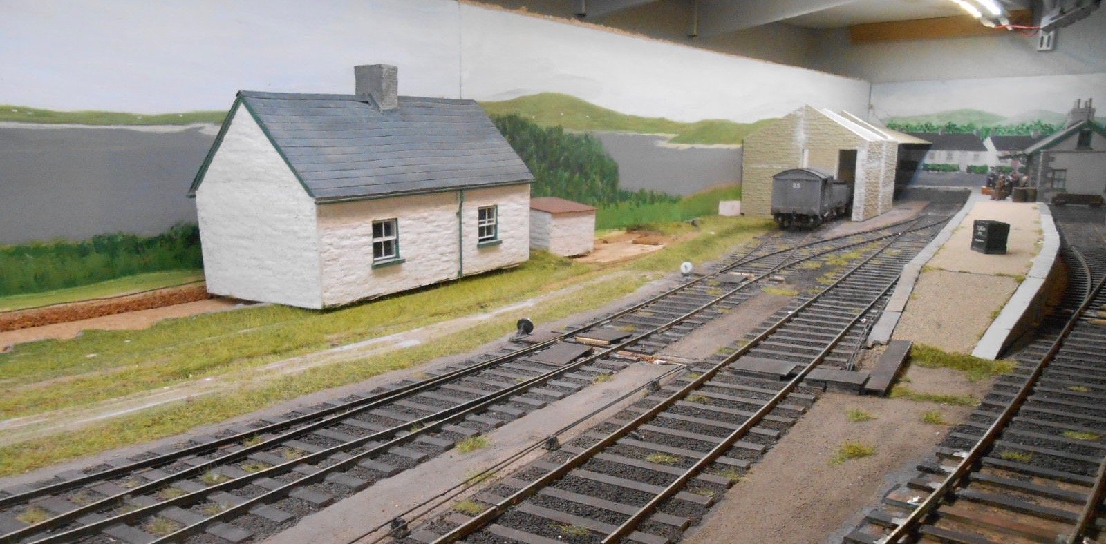
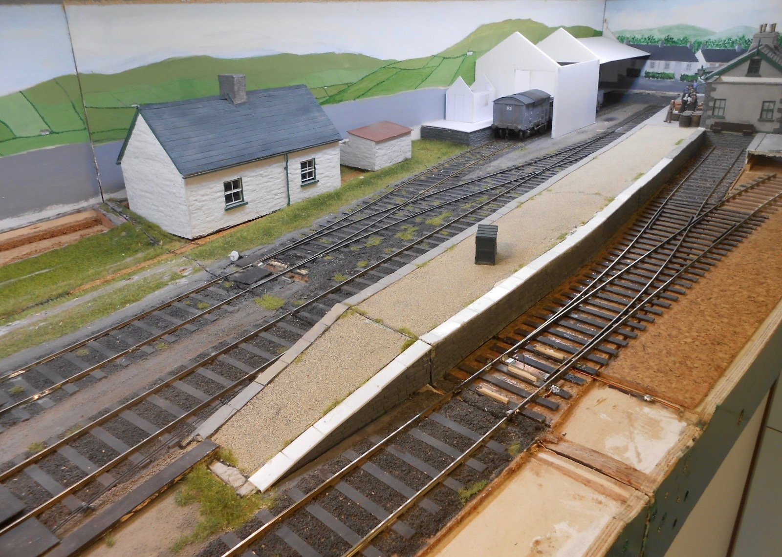
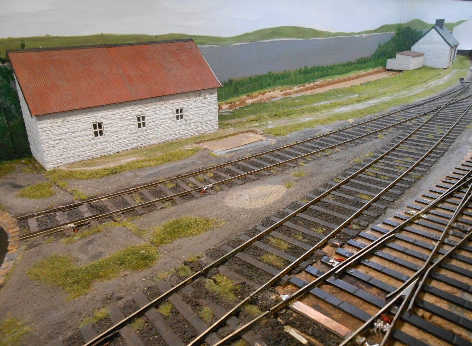
More 'blocking in' work recently. not very exciting, but gradually builds up the overall scene. The goods shed and loco shed have both been covered in Wills 4mm scale random stone, while the other buildings are rendered stone from the same source. The goods shed is about 3/4 relief, so a very odd shape, which has been done very much by trial and error - lots of both in fact! The windows on the loco shed are from York Modelmaking. With micro strip now costing around 50p for a 30cm length, ready made, laser cut frames are increasingly both attractive and cost effective. Other work, if you can call it that, has been a case of spending quite a lot of time just looking at the layout. Not hours on end, but little and often, in an effort to try and visualise the scene and get the overall balance looking right. Hence the cottage will probably now move to the right hand end of the middle board, so there is room for a bit of hard standing/goods yard effect next to the goods shed.
- 179 replies
-
- 10
-
-
How is it that ugly, modern buildings can make such interesting models? Never a problem with Warb it seems!
-
Astonishing stuff.
-
The Worsley 7mm one is ok too, with room for Delrin chain to make it 4wd. Presume the artwork is the same as the 4mm version, so note that it represents the later model. If you want the earlier one you'll need to adapt the windows.
-
Splendid, to say the least! What are the internal dimensions?
-
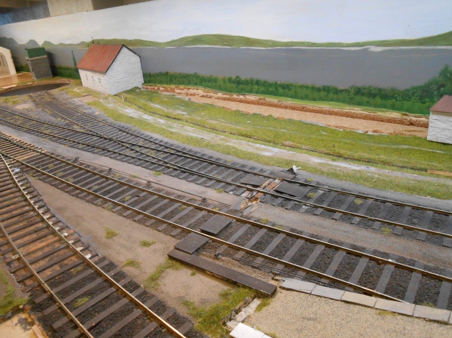
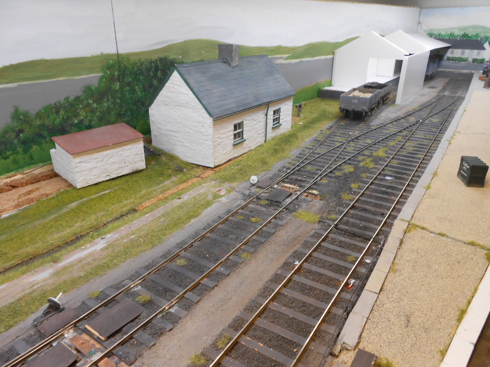
Adjusting tone and topography A quick comparison with last week's photos should show that the land has shrunk and the water level has risen. Fortunately not global warming just yet, so nobody needs to go out to source gopher wood or animal pairs for now. However, it was obvious that for this part of the Mayo coast, everything was just a bit too big and bright. Google Maps and Google Earth are very useful in helping to get an idea of a landscape far away from home and there are some excellent pictures online too, so the last week has been spent adjusting things accordingly. It is not in any way 100% accurate, but I hope I'm starting to capture the feel of the low lying, almost treeless Mullet peninsula, with Achill Island brooding in the distance. The latter should really be even lower on the horizon, but the back scene topography needs to be as high as the loco shed roof, while as mentioned last time, the sky behind will be on separate boards. I've pondered long and hard about the relationships between the 3D scenery and the 2D back scene - including doing away with the barn and cottage. A long of time has been spent just sitting in front of the layout, trying to visualise things and several sketches have been done too. At the moment, the buildings will stay, though I've angled the cottage to be parallel with the track in the look. The goods shed has been made longer, but also lower, so its roofline roughly matches that of the Co-op store next door. Mrs H has given her approval - she has a good eye for proportions, though this perhaps begs the question of what she sees in me. An unfinished project probably! Perhaps the biggest problem has been how to hide the baseboard joins in the back scene. I considered making the buildings removable [as on Fintonagh], but they would take up a fair bit of extra space when transported. Well painted trees can do the trick, but the area seems rather tree-less. However, checking photos again shows a few conifers, while some of the farmsteads look like they have windbreaks planted, so this is what I've done. The tones of the distant peninsula have been build up with numerous thin washes of acrylic, while I've done away with all the hedgerows and drystone walls. The more distant the landscape, the easier things get as everything tends to blur into a blue/grey, but middle distance requires a bit more colour [albeit pale] and detail. Whether additional washes will be added, depends on how it looks when I next go in the workshop, though the foreground certainly needs more work [it will probably wait until I start the actual ground cover, so I can best match the colours] and the two ends have had little done to them yet.