murrayec
-
Posts
2,775 -
Joined
-
Last visited
-
Days Won
70
Content Type
Profiles
Forums
Events
Gallery
Blogs
Everything posted by murrayec
-
until
-
Next Fair is on the 7th of April.

-
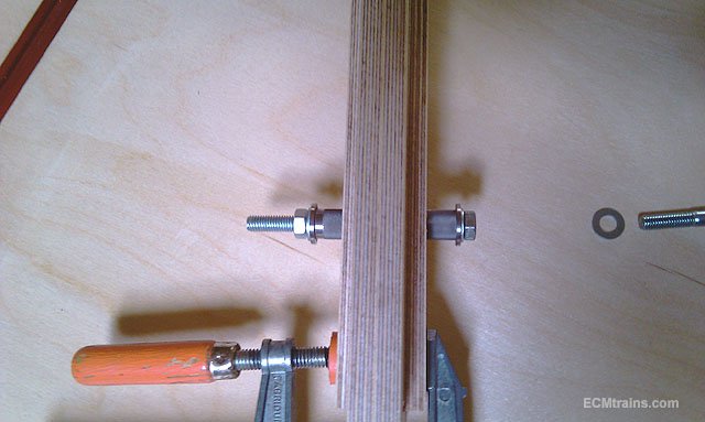
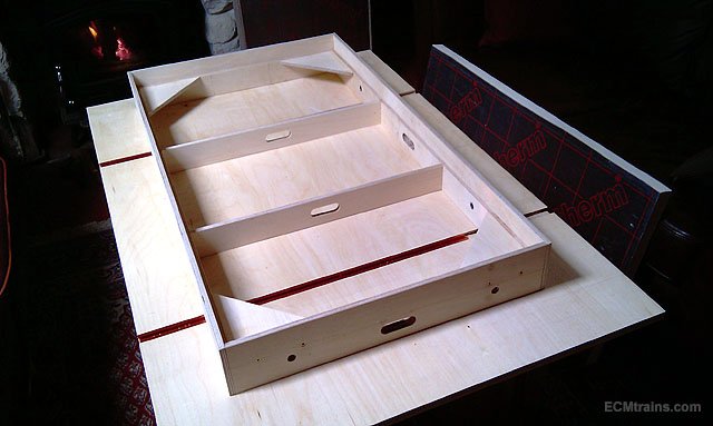
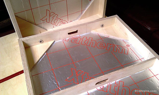
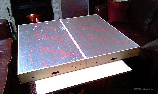
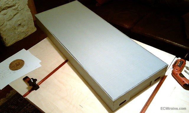
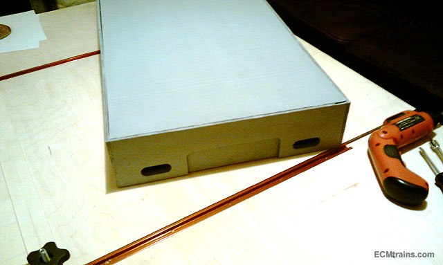
Back to baseboard! So I finished off the steel dowel and bolt system, drilled holes in, routed slots in, and stuck the frames together;- First, was to install the dowel sleeves into the appropriate sides, with sides clamped to fit the sleeves n dowels are bolted up to draw the sleeves into the wood. Once the dowelling was done the frames were stuck together with staples and wood glue, the gussets in the corners have horizontal screw fixings through the frames. 40mm insulation being glued in with No More Nails. Two of the boards bolted up for first test fit, can't put the other two on yet as the glues not dry! Now need to work out the track plan- see if any mods are required, and then we'r a painting...... Eoin
-
Hi Tom Do as Glenderg says- but if you have a multimeter and it does continuity test? you could first probe around on the oil and see if its conductive, otherwise test pickups to wheels, otherwise test from pickups back to the motor terminals- wiggle the wires n bogie also while doing this test... and see what happens Eoin
-
Stunning.
-
Don't forget the Fair is on this Sunday.
-
Hi joe123 You can get them on Expotools;- https://www.expotools.com/ and Amazon, or in Marks but call them first! This is what it looks like;- https://www.google.com/search?q=pin+point+oiler&tbm=isch&source=univ&client=firefox-b-d&sa=X&ved=2ahUKEwj1_bPTtI_hAhV0s3EKHbafAaoQsAR6BAgJEAE&biw=1280&bih=891 A light oil preferably plastic safe, the oiler you buy generally comes filled with oil, though you can buy them empty. I've used the Expo one and the oil was OK..... Eoin
-
@David Holman There's a scene in the station on the layout- two chaps in caps doing the light filling thing? I think I'm liking inverted buckets a bit better now..... Eoin
-
Hi joe123 A very small drop of oil to the wheel axle bearings from time to time- clean out old oil with a swab of kitchen towel held in a fine point tweezers, and look for hair and the like wrapped around the axles and remove it. Again only a small drop of oil on the axle adjacent the bearing avoiding the wheel if possible, a pinpoint oiler is the best man for the job....... Eoin
-
I don't like the inverted bucket roof look, I'd go with torpedo ventilators and internal lights I also pondered on those tripod items;- they could be ventilators?, or as popeye says they could be lids? or the buckets are the lids and go over the tripod? or the wire/chain to the top of the bucket might be a control wire operated through the ventilator?...... Eoin
-

CIE Laminate Coaches - Worsley Works - ECMbuild in 4mm
murrayec replied to murrayec's topic in Irish Models
Thanks Guys for all the comments fl It's going to be black n orange white stripe above window Eoin -
Alphagaraphix address = 23 Darris Road, Shelly Park, Birmingham B29 7QY. Eoin
-
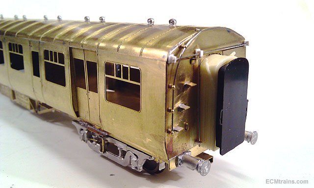
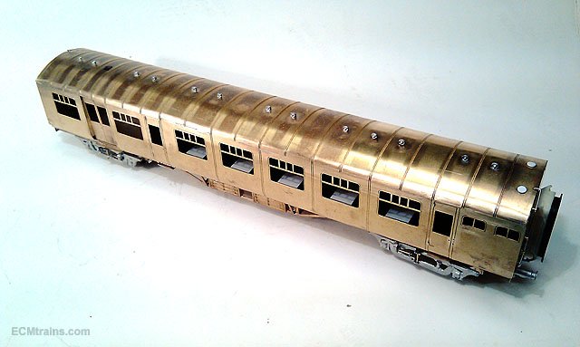
CIE Laminate Coaches - Worsley Works - ECMbuild in 4mm
murrayec replied to murrayec's topic in Irish Models
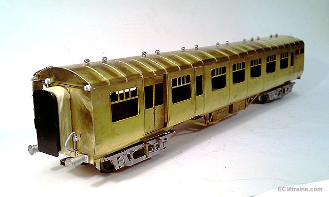
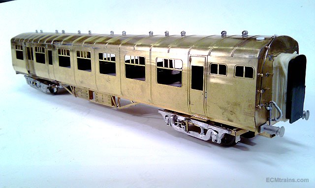
Well back to the laminate build! All soldering and gluing is now complete, a little painting prep now being done- I'm using Lidl W5 Limescale Remover to clean up the brass, it does a neat job removing oxidisation and flux. The first few panels of the roof have been brushed over with W5 with a paint brush and washed down with water- sparkly! After a scrub with washing soda, next were painting........... Eoin
-
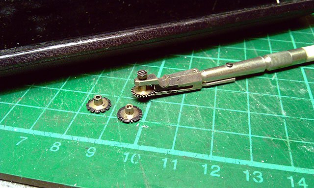
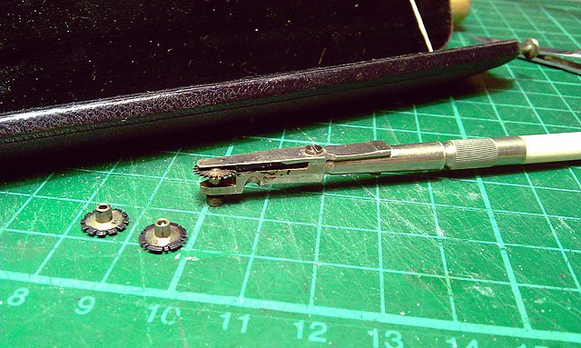
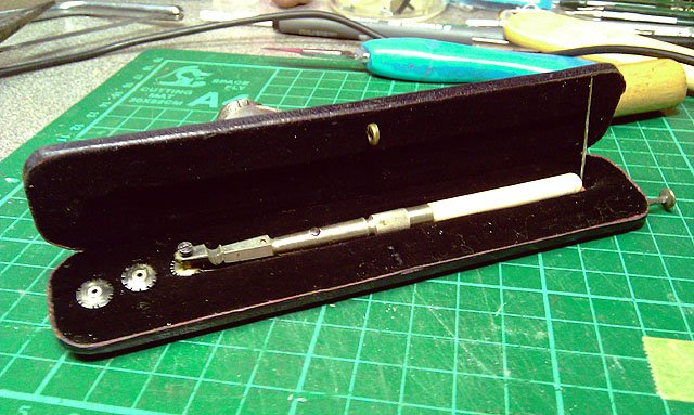
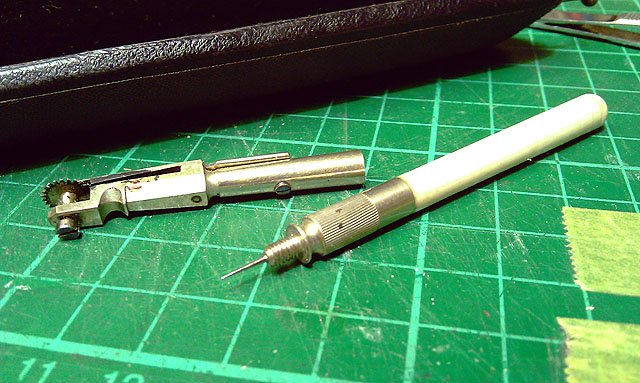
Nice find & buy @David Holman Your post reminded me I picked up a nice find also- a Lining Wheel Bow Pen for €5.00 Comes in a neat folding case with pin lock for putting in ones top pocket, Ivory type handle and a bow type affair to load the ink. Three interchangeable wheels;- dot dot dot, - dot dash dot, - & dash dash dash, the handle unscrews to reveal a pin! could be for loading the ink or for correcting mistakes? I plan to make a few continuous wheels, but there is only 1mm width where the wheel goes through the bow- so .3, .5 & .7mm maybe. Back in its box..... Eoin
-
I saw this back in 2017 not sure of the levels now! Article from 2016 ''Bachmann sells half as much as Hornby does in EU'';- https://masterinvestor.co.uk/equities/why-has-hornby-come-off-the-rails/ Eoin
-
Lovely looking loco popeye. Eoin
-
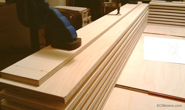
Main frames now laminated and clamped down to the bench for the day, just in case they might want to take a warp! Next step is to mate up sides and ends for dowel pin hole drilling and to route the wire slots ...... Eoin
-
Hi Cm It was made by Tyco Model Trains and is HO scale, here is a link to a bit of history about Tyco;- http://hotraincollector.com/mantua-tyco-streetcars/ Eoin
-
I'd like one of those for on the road! very handy for those chaps that cut you off in the traffic! Eoin
-
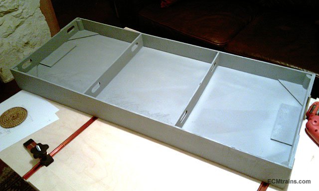
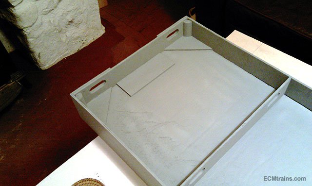
Hi Dave This in a Gauge N baseboard module which is the same construction design as the one above except;- it was constructed in cheepo 6mm ply with the 40mm insulation for the deck but has no laminated internal frame like the one above. The flat gusset piece in the corners are glued to the frame and to the underside of the insulation, the insulation is glued in with 'No More Nails' glue on the 40mm edge which makes the board fairly rigid in all directions, each module weighs in at 2lb. These boards fit end to end. The end plates are doubled up with a rectangular slot to take the support system, fixing two boards together involves sandwiching the support leg between the two boards in the slot and using a C clamp to hold in place. These units can go on a table or use their own support system! but I found it was to light and liable to be knocked over so had to add Lidl lifting weights to the leg bases. Eoin
-
Hi Irishrailwayman Yes hot glue is handy, but the majority of this system is laminated construction, there is a laminated inner frame for strength- when this baseboard is at home it will be assembled and hoofed up to ceiling level in my sitting room- for easy access and maximum fun! Hot glue wont work for laminating so PVA & nail gun it will be... Hi Noel I have seen your glass fibre tape & PVA construction in your posts! I'm not to sure about this construction- PVA is a soft material and would not give the same rock hard finish that resin reinforced with the tape would do, which is what's normally used with glass fibre tape, what I thought when I saw your post was, if one goes to the trouble of taping the joins and painting on PVA why not go the whole-hog and use resin! and Noel when things are hot- 'don't Touch' as mammy always said Eoin
-
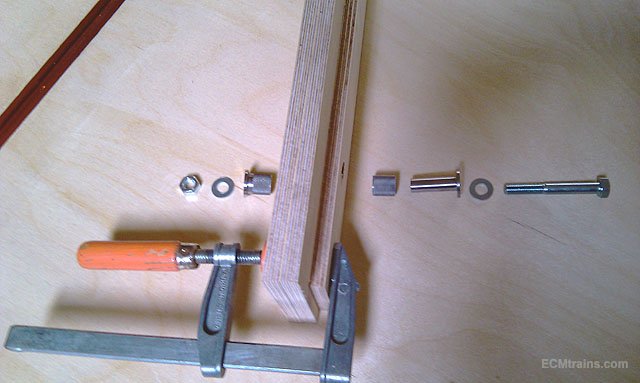
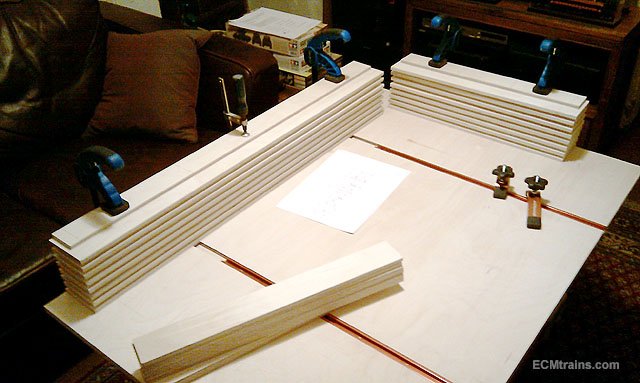
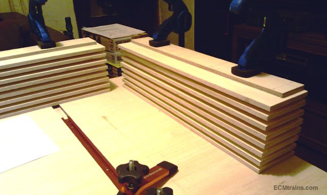
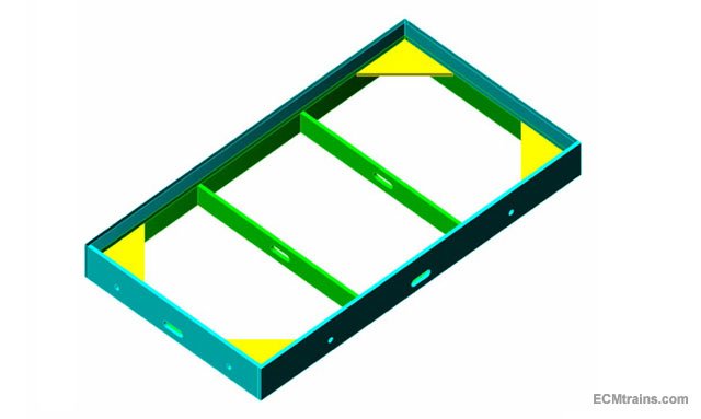
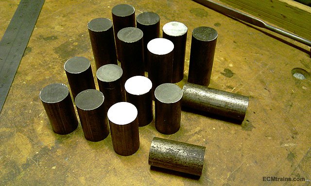
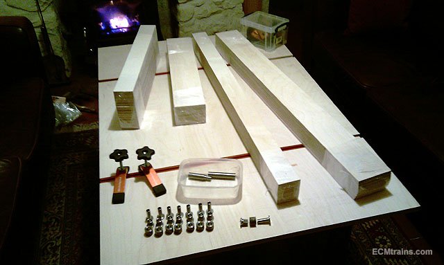
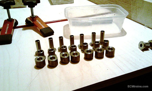
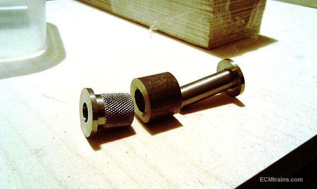
I'm setting up a Gauge 00 Exhibition baseboard 2000x1100mm which will take up to a radius 3 track plan, my design is based on lightweight construction so easy to move around, a four unit system 1000x550mm each, two x two of the units will bolt together making two closed transportable units which will fit on the back seat of my car. The baseboard will also be set-up at home to play with and to test models that I'm working on. This is a drawing of one of the 1000x550mm units which will be constructed in 9mm birch ply, it will have a 40mm expanded styrene deck (not shown) to keep the weight down, there are four M8 bolt fixings through MS dowel pins in each unit, to bolt the four units together. This is the 20mm MS bar stock that the dowel system is turned from- 1 dowel pin and 2 sleeves for each bolt which goes through the dowel and clamps the units together against the sleeves, the sleeves will be permanently fixed into each unit. The bolt and dowel pin are removed when disassembling so nothing sticks out the side for transporting. After a bit of turning, though not finished yet. A dowel pin and the two sleeves, one sleeve still needs a flange and a knurl put on it. And the 9mm birch ply frame parts kindly & accurately cut by baseboard Dave. Boards this size cannot be worked on in my workshop so I have made a ply worktable that fits to the coffee table in my living room with T Slot clamping system to aid construction of this and other jobs. Other items like sky boards, support system and scenery are planned and will come along later. The scenery is going to be based around Dun Laoghaire, Salthill and Seapoint- I hope, with keeping the baseboard compact we'll have to see how things pan out! Now for a bit of gluing......... Eoin
-
Excellent idea David, Looking forward to seeing this progress and how you handle the recycling transformation- an excellent layout that could go on for ever! JHB's book also inspired me to set up a drawing for a layout of the Achill station- one for the future...... Eoin
-
Excellent Ken, The makings of a lovely little train, looking forward to seen them painted. Eoin
-
Hi joe123 Here is a thought- what about removing the two acute bends and have the return loop there! that may be an economical solution. Eoin