murrayec
-
Posts
2,765 -
Joined
-
Last visited
-
Days Won
70
Content Type
Profiles
Forums
Events
Gallery
Blogs
Everything posted by murrayec
-

CIE Laminate Coaches - Worsley Works - ECMbuild in 4mm
murrayec replied to murrayec's topic in Irish Models
Hi Noel Not sure if doing hinges! Handles will be bent up NS wire guards and filed down dress pin heads for handles- these will go on last after painting is complete. Eoin -
CIE Laminate Coaches - Worsley Works - ECMbuild in 4mm
murrayec replied to murrayec's topic in Irish Models
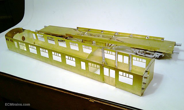
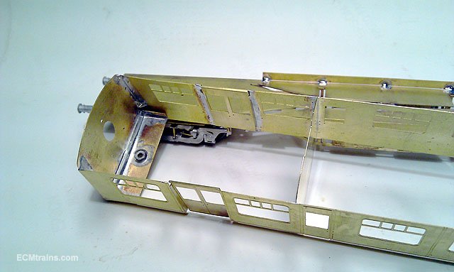
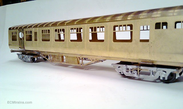
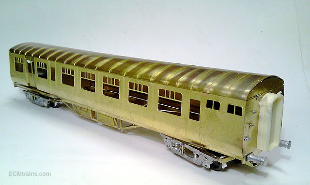
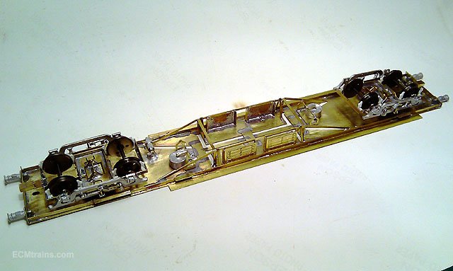
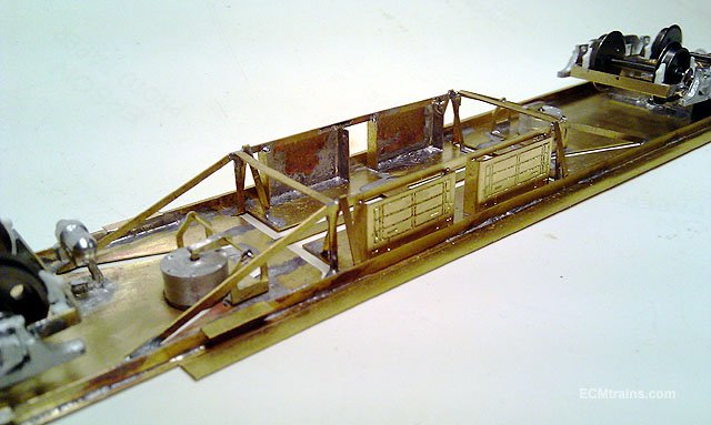
Thanks all for the great comments Next up, the body.... Body mounting brackets being soldered onto the ends with a spare bits of fret from the kit, underneath as spacers Sides being soldered onto the ends- because I soldered the roof access steps on the ends first! I had to do this mad jigging arrangement! Each side has an end soldered on like a 'L' and then the two are soldered together. All together with the internal divisions soldered in- toilets and break/store compartments. These bits don't come with the kit, their home spun. Test fit of body and roof. Some small adjustments required- I forgot to put fret spacers under the dividers when soldering them in! their low and hold the body up off the chassis, got to do that again. Looking good though Eoin
-
CIE Laminate Coaches - Worsley Works - ECMbuild in 4mm
murrayec replied to murrayec's topic in Irish Models
Hi fl I'll include a set of sides for you the next time I go casting them..... Eoin -
CIE Laminate Coaches - Worsley Works - ECMbuild in 4mm
murrayec replied to murrayec's topic in Irish Models
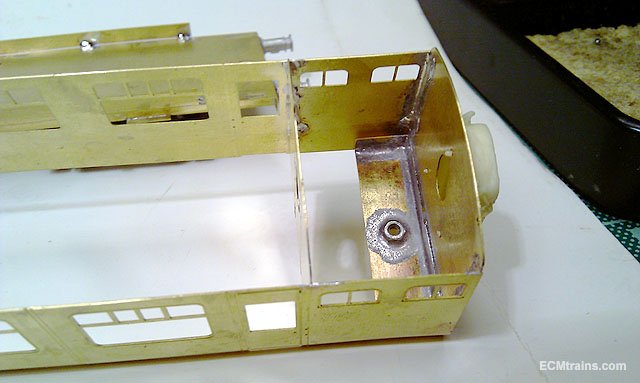
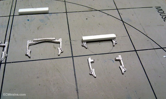
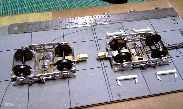
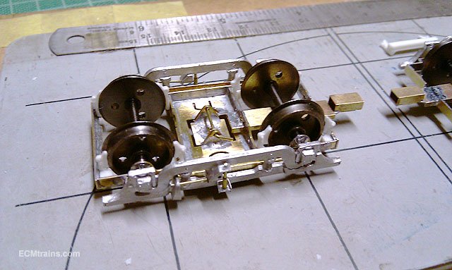
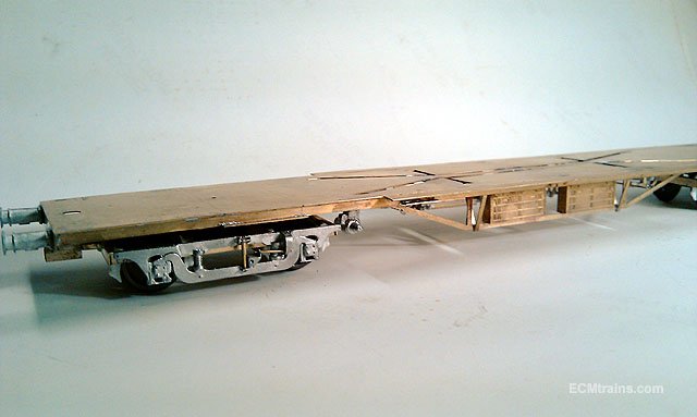
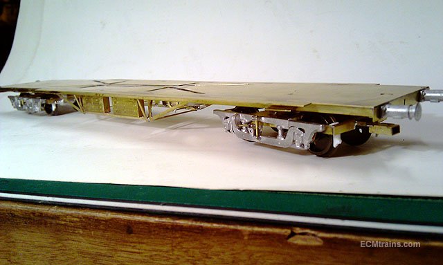
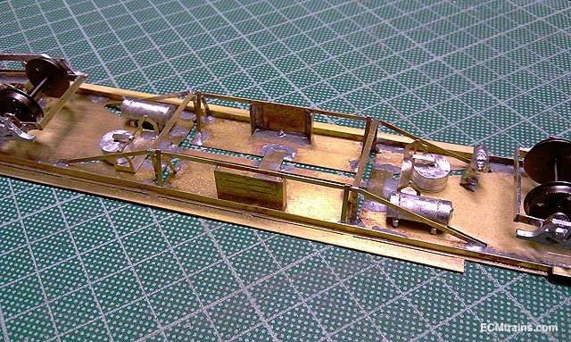
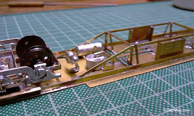
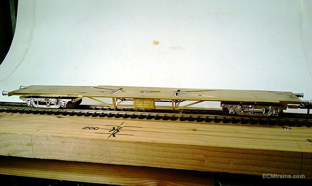
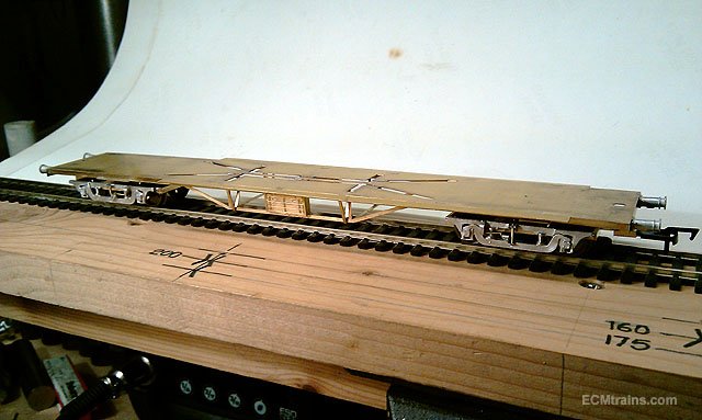
Break shoes! no point in doing the break cylinders and gear and not have shoes! Modified Dart Castings 2952 wagon shoes, trimmed down and stuck to a styrene bar for moulding for plastic casting. Moulding and casting done the shoes are being fitted to the bogie frames with epoxy. Little shoes. The chassis now sports 4 under-frame boxes- the existing boxes were de-soldered and both soldered on one side, 2 new boxes were made up and soldered to the other side. Break Cylinder, break shaft brackets and dynamo are 180deg soldered on. The new boxes. Chassis is more or less done, a few small fittings to go on and side angle folded up- ready for clean up and painting. Eoin
-
Hi jhb I'm not to sure, you would need to give them a call! I used to use Copy Graphics in Clonskea to do colour A1 prints in the architectural days- they charged €26 for the first print and then a lower cost for each copy- so at a guess if you set-up the artwork yourself possible a charge around €20.00??
-
Hi Noel Any print shop with large format printer or banner printer will do it for you- 'One to One' in Dun Laoghaire, Hackets, or Grants. If you set-up the artwork for A1 sheet or banner printing you'll save a bit on the cost Eoin
-
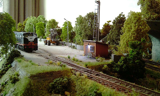
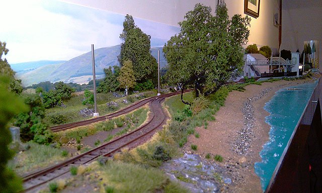
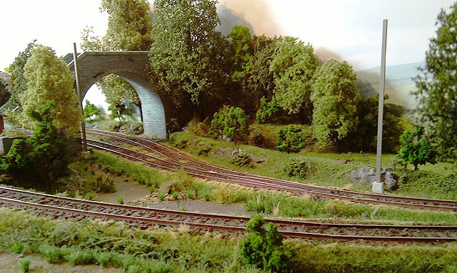
Hi Noel It's from Expo Tools - 95281 Hills & Dales, we bought 2 of them, it comes in 2 sheets each and we used 3 sheets for the length of the layout, one of the bridges & trees masks the join.... Eoin
-
Hi jhb The gate is from Studio Scale models- brass etch kit, you get a number of period gates to work with, the posts I made from styrene cut with hot wire cutter, all mounted on a brass sheet base yet to be stuck down and gravelled...... Eoin
-
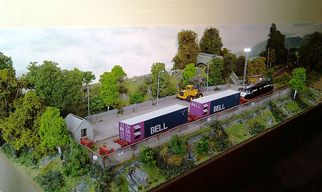
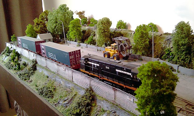
With the delivery of the final batch of trees before Christmas, the landscapers were on site today and installed 50% of the delivery, then the weather turned bad and the chaps did a runner- being Friday n all! We are assured they will be back next week to finalise the landscaping.... Eoin & CM
-
Excellent Glover All looks great. Love the yellow button detail on the pink cushions- now that's rivet counting Eoin
-
CIE Laminate Coaches - Worsley Works - ECMbuild in 4mm
murrayec replied to murrayec's topic in Irish Models
Hi fl Thanks for that, I remember seeing them on the tracks! so thats were the belts came from...... I must build that in- every so often it will throw a belt! Eoin -
CIE Laminate Coaches - Worsley Works - ECMbuild in 4mm
murrayec replied to murrayec's topic in Irish Models
Thanks josefstadt Yes the extra storage tanks are out and the extra battery boxes are currently been cut out for installing..... Great photos again, thats the first one of a break coach I've seen. In your previous issue of photos, on the second photo the generator seems to be driven by a belt from the axle on the bogie! Is the generator mounted off the bogie frame or the coach floor? I would have thought with the bogie swivelling there would be problems with a belt if the generator is hung from the floor!! any views on this guys? Eoin -
CIE Laminate Coaches - Worsley Works - ECMbuild in 4mm
murrayec replied to murrayec's topic in Irish Models
Thanks jhb I'll make it four, as you say makes perfect sense, it was in my mind at the start of this but somehow went out of the head!, and we've gone to the trouble to get the boiges right I'd like to get it right overall Eoin -
CIE Laminate Coaches - Worsley Works - ECMbuild in 4mm
murrayec replied to murrayec's topic in Irish Models
Thanks fl, OK so no storage tanks, on the boxes- yes that confused me;- the break coach kit came with only two battery boxes and the standard came with four! All photos I've seen so far have four boxes,- not seen a photo of a break though. But I assumed as supplied in the kit the break only had two! it would be a nasty bit of de-soldering to change the chassis above to four box....... @jhb171achill What do you think? Eoin -
CIE Laminate Coaches - Worsley Works - ECMbuild in 4mm
murrayec replied to murrayec's topic in Irish Models
Hi From josefstadt's posted photos above- very handy, it's quite hard to find photos of this coach type up close! there is no sign of storage tanks under frame! What do we reckon?- this is a break coach would it have had storage tanks? Eoin
-
CIE Laminate Coaches - Worsley Works - ECMbuild in 4mm
murrayec replied to murrayec's topic in Irish Models
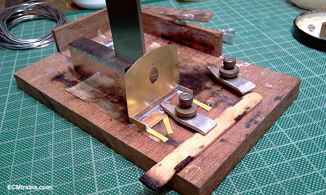
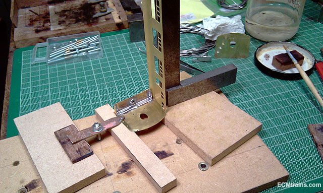
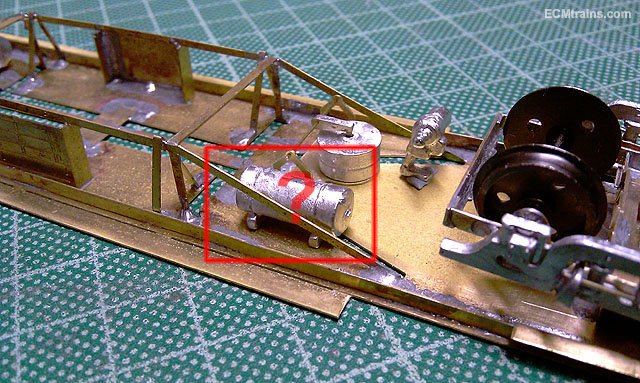
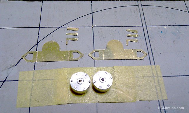
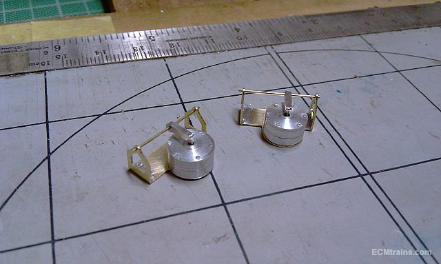
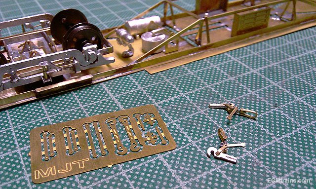
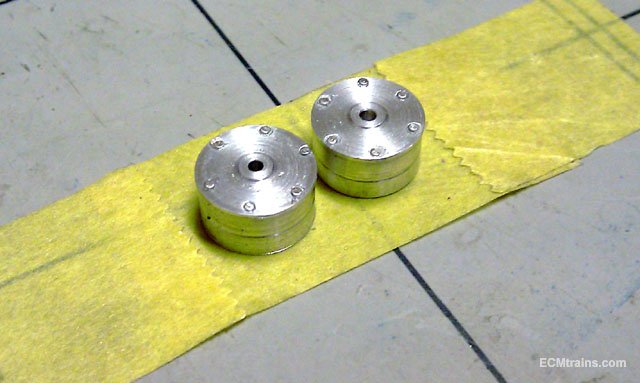
First Parts of 2019! Happy New Year to you all...... Brass parts cut out of .39mm brass sheet, needing a bit of an edge clean up, fold, and then solder. All done, with a .5mm brass shaft to be soldered in when going onto the chassis. Making the mould to cast the tanks in whitemetal was then done and the first casts tested today! Placed on the chassis to check final location. And screw coupling linkage- I have a packet of these MJT etched kits and this is a good excuse to try them, their a bit fiddly but look good when finished. Not sure how they will work with the bogie coupler! they get in the way..... Here is a question;- Did Laminates use generators? if they did from what period, this coach livery is Black n Orange?? also- any photos? Eoin
-
Excellent job Ken, It looks great, looking forward to the painting Eoin
-
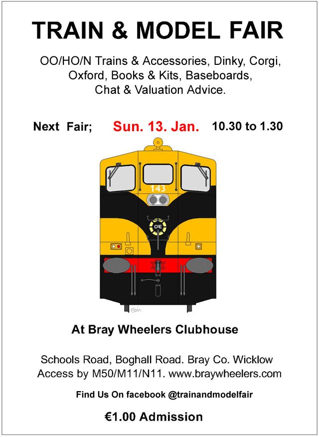
The first Fair of 2019 is on Sunday the 13th of January.....
-
CIE Laminate Coaches - Worsley Works - ECMbuild in 4mm
murrayec replied to murrayec's topic in Irish Models
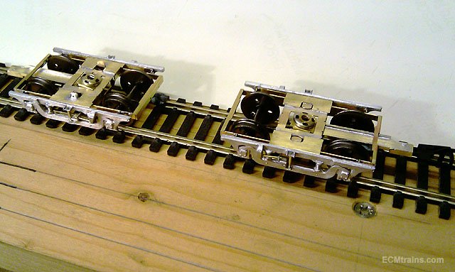
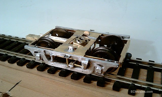
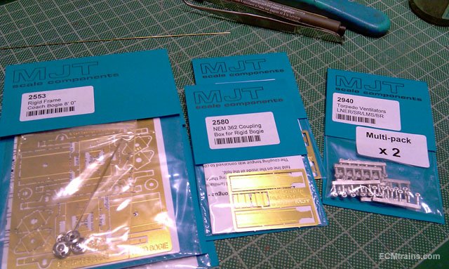
Thanks guys for kind comments MJT 8' bogie frames were put together, coupling bar n socket added and the sides glued on with epoxy- a nasty bit of soldering there, liable to see something melt so glue is your man! and on the chassis and these are the patterns to cast up break vacuum cylinders There are a few brass bits to go with these, yet to be cut out........ Eoin
-
CIE Laminate Coaches - Worsley Works - ECMbuild in 4mm
murrayec replied to murrayec's topic in Irish Models
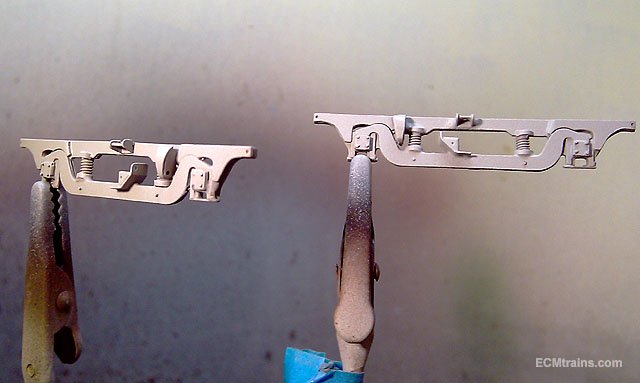
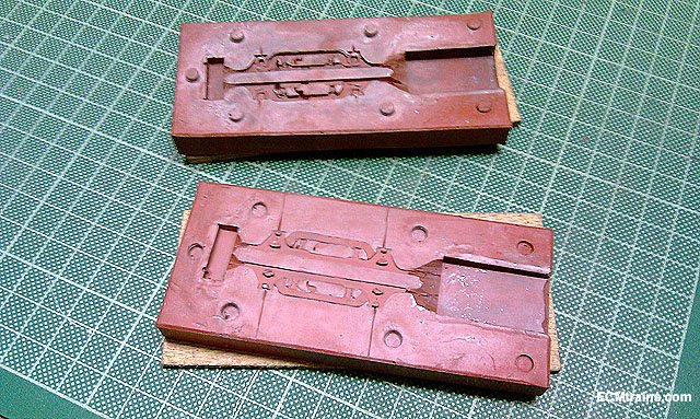
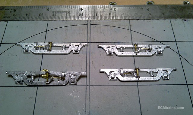
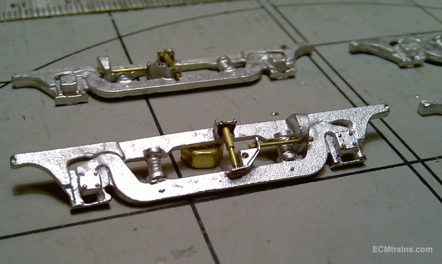
The bogie sides were completed today, some difficulty with the mould so I'll have to revisit that! though I got 4 sets of sides out and I can now proceed with the laminate coach;- Painting and filling the side patterns, The mould, you can see where I cut vents out to the side of the mould, I also drilled hole through the mould to get the suspension shock brackets to work- these are a bit thin and I think they have to be beefed up next time around, Castings with brass shock and torsion bar installed A bit of a rub down with the fibre pen is required, The 8' 0" bogie units and roof vents eventually arrived, so their next Eoin
-
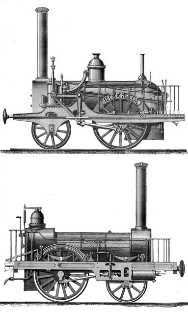
There is a certain magic to them, but unfortunately on the Hibernia- 'super' was not the case! This loco was an 'Experiment' by Mr Roberts, he designed vertical cylinders with a bell-crank to turn the motion to horizontal and that was it's downfall, he ran a few of this type in England but very quickly they were removed from service- the loco bucked from side to side, pounded the track, and leaked steam from the cylinders which they could not stop. I reckon the spares from the 'Experiment' were sold off cheep to the D&KR- against the protests of the D&KR engineers, by Sharp Roberts after languishing in the corner of the shop, only too delighted to supply the locos with engineers for two years to be rid of the stuff. The D&KR did run three of these locos for several years and they gave good services for the bargain price, all removed from service after one of them exploded in Kingstown when left unattended running with low water in the boiler. What a pity one of them was not held on to....... I'm building models of this loco- the Gauge O early development test work can be viewed on my workbench thread- work is progressing very slow but I'm at the brass cutting out stage now, other scales are been worked on with a Gauge N about the most advanced..... Eoin
-
Nice one
-
Here are the first two locos, the Hibernia & the Vauxhall
-
I bet the Missus is impressed! Eoin