murrayec
-
Posts
2,775 -
Joined
-
Last visited
-
Days Won
70
Content Type
Profiles
Forums
Events
Gallery
Blogs
Everything posted by murrayec
-
Hi joe123 If the temp road bed is held down somehow so that the chain cant push it up that might help! The chain relies on the under road surface to keep it down when there is to much friction. The reason the chain pushes up is because of friction on the bends- the chain on front is going slower through the bends than the chain following behind, the chain behind will go where the least resistance is- that's up if it can push the road surface out of the way! More motors and return loops on those acute bends should help with countering friction- but do try fixing down the road surface first and test again. It would be best if the chain glides around without the road surface on! Eoin
-
Hi joe123 Thats a lot of Magnorail. When you say 'cant get the right tension on the chain' - what do you mean? Is the chain connecting up? or, Is the chain slipping? or, Does the chain run OK without cars on, and doesn't when their on? In the third photo I see a rather tight curve! for a curve that tight one should use Magnorail's return loop (modified) which will reduce friction. For 6 meters of soft curve rail you should have at least 3 motors- which may run up to about 6 cars. With the layout you have done and if you want to run more than six cars I would put a motor in per meter of track = 6 motors! If you use the return loop unit on the sharp bends or increase all sharp bend radius you may get away with 4 motors. Am I right in saying that you have two separate Magnorail tracks of 6 meters long each? If thats the case you'll need to up the motors on both! I know that might be not what you want to hear, but Magnorail is really designed for nice wide radius loops and small layouts! Eoin
-
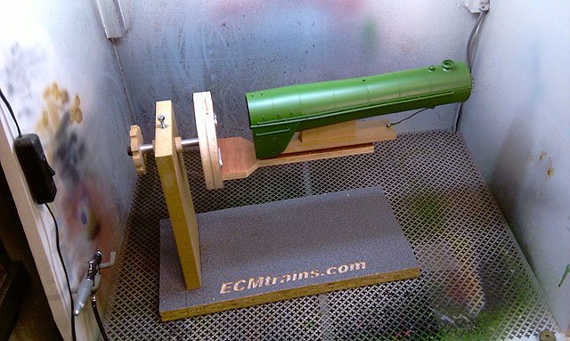
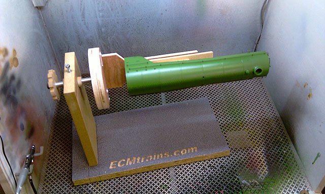
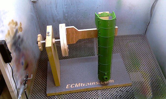
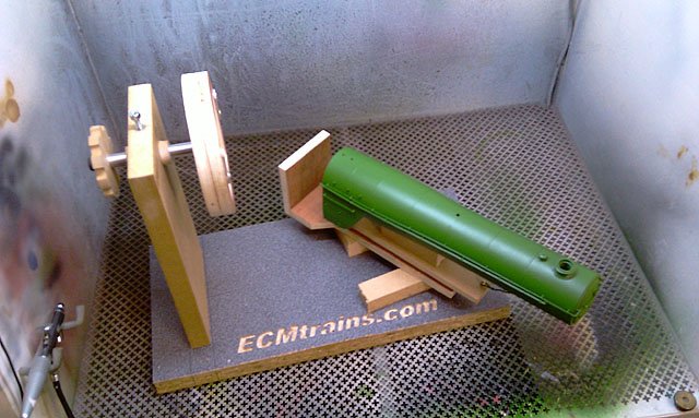
Another paint spraying jig. A 'two axis rotational jig with interchangeable parts cradles';- And turn it this way..... And that way...... And the cradle dismounted for the next part to be loaded! I've made four cradles of this type and a few more variations are on the drawing board yet to be cut out. Eoin

-
Hi I have some knowledge on Magnorail- What is happening? What length is the Magnorail chain? if over 1.5m do you have more than one motor? What are the radius curves your using? Any other info you can give may help- especially photos of the Magnorail layout Eoin
-
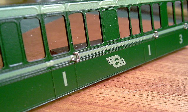
Hi popeye The test styrene side is scored with the Cameo Silhouette knife for the bumps so not like a model side's deep and wide relief, I used a few drops of PVA in the water as recommended by Railtec's instructions, they say this is preferred to MicrolSol, also to avoid MicroSet. I could not encourage the decal to sit down into the score lines but that might have been expecting to much! But the decal is pretty strong as I had to manipulate the lining with a stick and bud to get it in position with no tares, reckon it will work OK on the actual model sides. I have another styrene side which I'm going to put the high relief vents on and test again. Door handles and guard went on after the decals. Eoin
-
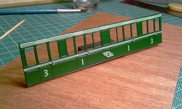
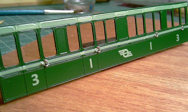
Here is a test of the Railtec Transfers on a piece of flat cut out styrene for a 6 wheeler lav coach, the green paint is Humbrol 3 and after transfers were on finished with semi-matte Alclad II;- I reckon the colour for the lining looks quite good. The pinstripe is only on the narrow line but looks clear. I bought the 4mm-5635 n674 sheet as it had the smallest logo for this type of coach, but as popeye mentions above the numbers are a problem! - you get enough of the small logos to do ten of these coaches but only enough 1, 2, & 3 numbers to do four & a half of these coaches- it would be great to see the numbers 4 to 0 changed to 1, 2, & 3 on the sheet! If there is to be an edit on this sheet regarding the numbers I would suggest making a separate sheet for the 6 wheelers and I would suggest scaling the logo and numbers down by a .8 factor..... Otherwise I will be using these. Eoin
-
until
-
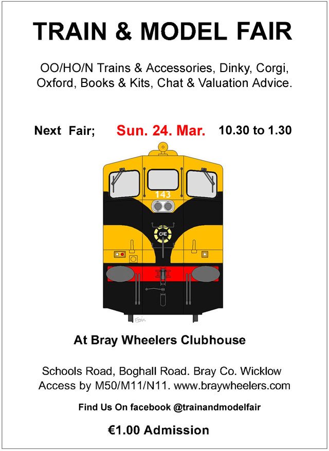
Next Train & Model Fair;-
-
Hi Heirflick Do a sharp pencil sketch around the edge of the part on white paper- as close to the edge as you can get it, also measure the overall length, the thickness of the part, the diameter of the pins, the height of the pins and include them on the sketch, scan the sketch to a jpg and send it by pm to me .... and we'll see what can be done! Eoin
-

Glasgow Exhibition 2019 MRSI Prize Winners
murrayec replied to Irishrailwayman's topic in What's On?
I love Brendan's Crane. Great layout and stock, Well done lads..... Eoin- 2 replies
-
- 3
-

-
- glasgow exhibition 2019
- mrsi winners
- (and 2 more)
-
Hi Riberac For fun switching operations I reckon the more sidings, the more movement operations can be done? For funny switching operations you could always tell jokes while running the layout Eoin
-
Hi Wayside Just click on the two links I gave you above last night and all info is there;- First one is a long running thread since it was removed from Malahide. Second one is up to date news by the chap building the OO layout. Eoin
-
David Have a look here;-
-
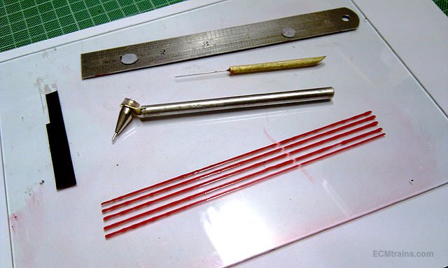
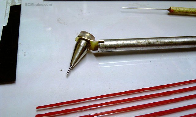
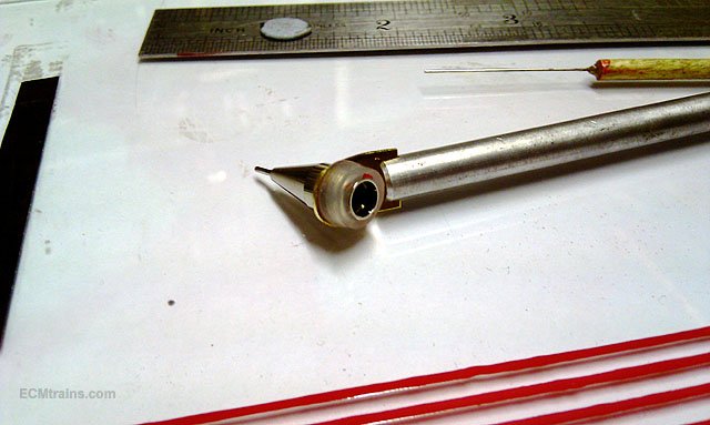
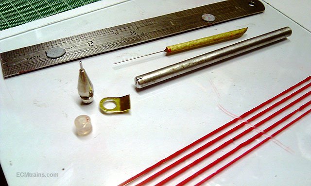
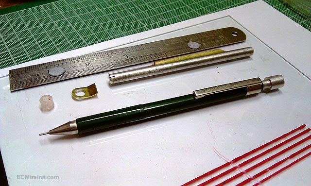
Here is a handy and economical way of making a paint lining pen;- This is the unit with a few sample lines done on glass. The tip is .5mm but the lines spread out as I had to thin the paint, an old can of thick enamel! - if thinning the paint it takes a fair bit of testing to get it right and best to test on a sample card of the paint your going to line. I'm a bit rusty at doing lining and this was the third attempt for posting this thread, more practice is required- speed is the key, a constant speed, when you have the paint right! The components- .5mm tip, scrap brass to hold the tips, silicone tube off cut to clamp the tip in the brass holder, 6mm aluminium bar handle with slot to take the brass, and a .45mm NS wire prodder to clean the tip. And yes you probably guessed it- the tip is from a Faber Castell mechanical pencil 'Contura' range- for about €10.00 which comes in .3mm, .5mm, and 1mm lead sizes. I do have a .3mm pencil but could not locate it for this posting, I also have an adapter that allows the lining pen to follow edges and the like , and it's adjustable, but again a problem locating it. I also recently bought .2mm dia NS tube to make a .2mm tip- I will post a photo when made and hopefully I'll find the other parts by then? It does take a bit of practice but when the paint is right and the pen mastered it does beautiful lining.... Eoin
- 1 reply
-
- 2
-
-
David Another excellent book is Mr Christopher Vine's 'How (not) to paint a locomotive' ISBN 978-0-9553359-0-7 There is an excellent section on lining a loco, he more refers to RL Moore's lining pen, the Beugler Pinstriping tool, and masking film. His discussion is filled with helpful tips, things not to do, and gadgets he makes to assist in lining. The rest of the book is a mine of information for painting a loco, he's working in large scale but the paint can't tell the difference.... He is a 2004 gold medal winner in model engineering for his stunning 7 & 1/4 inch gauge LNER B1 'Bongo' Eoin
-
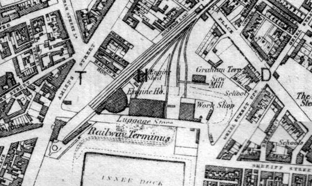
Hi John The 1880 map showing the goods yard and extended works I don't like Connolly Station now it's such a mess, but I see Amiens St terminus in a whole different light! It's going on my list after I complete the Kingstown Station layout. Mike Sharman- I saw a number of his loco many years ago at a show in the UK, his Crampton locos impressed me so I started to research Irish locos of the same vintage and came across the 'Hibernia' and it's sisters and have developed the drawings for D&KR 1834 locos, some of the Hibernia preliminary work for Gauge O is on my workbench thread. I just recently purchased his book on the Crampton Locomotives which is an incredible insight to the engines, stunning drawings and excellent tips to modelling them. Again another project on the list..... Eoin
-
Hi David Grab a copy of Ian Rathbone's Book 'Painting & Lining' by Wild Swan Publications ISBN 978 1 905184 54 5 and its in colour!! He has all manner of tips n jigs for working with enamel paint and bow pens, excellent tips on cleaning up mistakes without resorting to sandpaper Eoin
-
Excellent Glenderg, Roundhouse it is. I saw some of that detail in the planning documents but the scan by DCC was to black& white and the detail was almost imposable to make out because of the tone over the structure! One thing about luggage back in those days, it wasn't just suitcases! Some folk who travelled to their country houses brought their furniture with them- no point in splashing out good money on a second set when it would just sit around for half the year. They would pack up their house and street cart it to the station or special facilities like Brownsbarn out on the Naas Road for delivery to their destination. This is one reason why a lot of houses in Dublin had rear enclosed coach buildings, they could sneak out the furniture at night to the rear so they would not be seen and shamed. Brownsbarn and some of the other companies provided huge carts pulled by oxen (cheaper to hire) and deliver to luggage stores in the one go and then street cart it to final destination. The Brownsbarn building we see today is about 1/3 of what the company had to store luggage in as it was been prepared for the journey. Eoin
-
Hi Garfield Yes I think that is most likely what it was for, also the issue of street level arched openings?;- I found a reference to the 'station being built on 27 arches to raise the track 24 foot above Amiens Street and a number of arches were used for storage of luggage, this is now the 'Vaults Bar''. These arches were accessed from the Eastern side adjacent to the Inner Dock and the building of our discussion is in the right location to transmit luggage down from a train and out through the arches to this storage area or through the link to the East Luggage Store building on Lower Sheriff Street.....maybe? Eoin
-
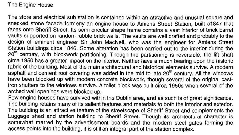
I did a bit more searching around and found more on the Amiens Street 'Engine House';- I found a far better map dated 1880 similar to the map above, with 3 buildings to the East of the station- all text labelled! 'Engine Ho.' for the building we're discussing, East to that 'Luggage Store' with a narrow connection back to the first building, and then East again 'Work Shop' on the building just before Lower Sheriff Street turns towards the Liffey. While browsing Glenderg's photos again, I noticed a planning application notice on the wall of the second building in the last photo so I did a planning search on the DCC website and came up with two items;- First;- a planning application for a dreadful major development of the whole station yard, the surrounding streets, offices and apartments towering over everything, permission was granted but noting in the documents relating to this discussion. Second; a planning application in 2007 Ref; 5696/07 for demolition of a structure on top of the 'Engine Ho' and erection of a new driver facility- which is the building we possibly see in Glenderg's photos, possibly because this application was invalid! lucky though they left the documents on line for us see;- Attached to the application is a Conservation Report as Connolly Station is a listed structure, in the report they describe the building as follows;- 'Engine House located at basement level running parallel along Sheriff Street and consists of three no. brick barrel vaults running east west supported by random rubble stone walls with arched openings'....'To the south of the building is the electrical sub station'... 'The walls consist of large white washed random rubble stone walls supporting the large barrel vaults. Several random rubble piers are located throughout the building'.... 'Several arched openings connect various rooms throughout the Engine House. The arched openings vary in size and consist both of brick and stone construction. Several openings have been blocked up in later years with concrete blockwork'.... Near the end of the report they say;- They also mention that 'an extension of the public platform to the East extended over part of this building', so some of the Engine House is under the platform and not seen from Lower Sheriff Street. It seems to be a cavernous sub-divided structure internally- a bit strange for an Engine House! and how did they get engines in? and why did it have large stone arches openings in the curved wall onto street level? Actually the curved wall is made up of 6 to 8 straight walls in an arc...... Eoin
-
Hi Wayside Yes there is something wrong with the lens all right? Though I can see it a bit better- the nut, bolt n washer idea should work like the Craven coach fix, sticking the washer on the underside of the bogie will be a bit fiddly to get it on centre, but it should work- saves buying new bogies... 'I like fixing stuff rather than buying replacements' Eoin
-
Hi Wayside It looks like the fix could work on the Lima, but if you could do closer up photos of top & underside of the bogie, and closer up looking down on the chassis socket/bolster I'd be able to see better? - fill the photo frame with the bogie, that close..... Eoin
-
Hi Dart8118 The Dublin & Kingstown Railway was constructed on a raised fill so not to interfere with the established streets of Dublin, the arches were constructed so public access under the rail line was provided as their was quite a bit of objection to constructing the line and cutting people off in their established communities. The turn table was for turning locos and tenders to take trains back out of Westland Row for the return journey to Kingstown, they did similar in Kingstown and I read that they disconnected the loco & tender on the move before the station, allowing the train to run into the station on a slight up hill and relying on the guard to apply the breaks! The loco went off to the Carlisle pier turntable and then came back for the return to Westland Row K A Murray's book is a great reference for this line I believe the steps and extension platform are much later additions Eoin