

Horsetan
-
Posts
2,336 -
Joined
-
Last visited
-
Days Won
4
Content Type
Profiles
Forums
Events
Gallery
Blogs
Community Map
Everything posted by Horsetan
-
Can-kicking is cheaper
-
I'm not sure if I had a sense of surreality or absurdity as I read that. Maybe both....
-
Anything that sheds a bit of light is welcome
-
300 quid is etched brass and n/s superkit territory anyway. I think there's a lot of us in the hobby who feel entitled to have top-notch models at rock-bottom prices - that's how the Internet has conditioned us to think. It's an extension of the oul something-for-nothing. In a weird way, if you go back to the days when real railways were still being built, people wanted new lines....but didn't want to pay for them either. The more it changes, the more it stays the same.
-
OK so, we're back in Urie N15 wheel territory again.
-
Food waste is such a terrible thing.
-
Interesting. Can the 6'3" diameter be verified? The only sources I have are Steam Index and the Clements & McMahon book, both of which state driver diameter was 6'7". Also, if you look at a broadside photo of a B1a and run a ruler through the driving axle centres and forward, does the line set by the ruler touch the top of the bogie wheels? At 6'3", the radius / midpoint is 3'1½", which would almost touch the top of the bogie wheel tyre. At 6'7", mid point is 3'3½", which would show a gap.... See also @KMCE's section drawing: I'd say the axle midpoint line sails way above the top of the bogie wheel tyre....so 6'7", I think.
-
The coupled wheelbase comes out as 7'3" x 8'6" (29mm x 34mm in 4mm scale)
-
Not only webbed spokes, but also crankpin between the spoke. This one is for 21mm gauge, not OO. The only contact I have with 16.5 these days is in HO. The Scalefour Society's annual Scaleforum show is on at the end of September; the Alan Gibson trade stand usually attends, so there'll be a chance to compare the King Arthur and T9 wheels for suitability. Likewise 247 Developments will be there and hopefully will have a stock of the nameplates. At this rate, I might have to build some 21mm test track.....
-
I think the rule is that the key leads the direction of travel, so it's inserted ahead of the chair for forward movement; as the engine moves, it effectively claws the rail and key back into the chair.
-
In looks, yes. But T9 wheels might be an expedient solution to reduce the possibility of the motion jamming up. The only other way is to redrill the King Arthur wheel for a shorter throw, but you need a jig to do that properly.... The T9 has a throw of 9 inches, the King Arthur is more like 13/14". Here's a view of Ultrascale's King Arthur wheel: ^^ Note that this is the later Maunsell wheel with the crankpin between the spokes, but you can see the almost-but-not-quite shape of the hub and the crank. The rim is also reinforced, so the Maunsell wheel is not correct for a B1a. The B1a throw is unknown at the moment, but may be between those two - maybe @KMCE's drawings might tell us the measurement if they become available. Unfortunately, the works drawing uploaded by @BosKonay years ago in Forum Resources is unreadable because it was a low resolution scan, so all the handwritten measurements on it instantly get pixellated when you try to zoom in. I had a dig around and found a set of old Sharman P4 3ft 9-spokes. They are a plain wheel, so the bogie is catered for. Just need the axles. Incidentally, the kit came with a Mashima 1430 motor and High Level packs to build an extended drivetrain. I can't stand worm gears, so a coreless 1624 RG4 with a proper bevel-and-spur drivetrain from my RG4 drawer is now the substitute. ...and once you've noticed them, you can't unsee 'em! One thing I forgot to mention is that the kit has its own beam compensation system designed in if you want to use it. I'm hoping we can adapt something a bit different in the form of a continuous sprung beam, as explained by the Central London Area Group - the wheelbase is similar to the LMS Black 5 and BR Standard 5, so it shouldn't be difficult to work out the measurements for pivot points and so on. One advantage of CSB is that it is less cumbersome than traditional beams, but you may need to modify frame spacers to allow the spring wire to pass through.
-
Funny, though, that all three types were touched, in one way or another, by lack of money. The B1a: coal shortages, then dieselisation and lack of work The VS: the GNRI was insolvent by 1958 The BP 0-6-4T: designed for a railway that couldn't afford to take it on Now, here's a Flickr view of some of those forked rods: In particular, note the way the radius rod divides into two to pass through the 3-layer expansion link. Combining lever, crosshead drop link, and small end of the eccentric rod are all forked. The valve spindle has its own rectangular mini-crosshead which itself is driven via a short forked link from the combining lever. You do wonder if the kit design will tolerate the addition of these refinements without jamming up.....but they're impossible not to see. Wheel construction is another source of fascination: see how the tyres are retained by setscrews between the spokes. There's a glimpse of the leading crankpin and I can see how close its position is relative to the axle centre, meaning that the crank throw is quite short - so that might mean my suggested King Arthur wheel might not work properly as that one has a longer crank throw (the pin is further away from the axle centre) which would cause the crossheads to travel further. There is a possible alternative wheel which could fit the bill: the LSWR T9; same diameter, same number of spokes, but a much shorter throw. I think we need to have a look....
-
This giant undertaking appeared on a notorious auction site a week or so back. Although I've admired @Weshty's magnum opus since he launched it a while ago (is it really 13 years!???), it wasn't a priority and, anyway, there have been loads of other distractions that were more urgent. When this one popped up, the description "Model Locomotive Kit" - that's all it said, I kid you not - was less than prepossessing. Only the auction photos made it clear what it was, and I started thinking that Maedb might be possible one day..... After a dying seconds bid, it fell to me, coming in at about 80 Euros less than new. For anyone thinking about having a stab at the last word in Irish steam, this is what you get for the money: - loco and chassis etches: - quite a lot of castings, turnings, a resin mould, and many sundries including more than a few types and diameter of wire.... For some bizarre reason there were also enough parts to make 2 sets (8, in other words) of sprung buffers - another two etches for the tender: ....and to cap it all, you get 20 A4 pages of densely-typed, illustrated instructions and parts lists. I've turned all that into a PDF so I'll not be stuck for a copy. You also get numberplates, but not the elaborate nameplates. All three class members' plate sets are available, ready-painted, from 247 Developments. It should be clear from the preview photos that this is not, and can never be, a beginner's kit. There's just too much of it for that. You can see where @Weshtyput in the hard graft and quite likely burnt the candle at both ends to get his artwork just so. That said, he wasn't mad enough to go overboard, so some of the valve gear has been simplified - there are no forked joints or forked rods at all, whereas comparison with the real thing in Cultra will show loads of them. It will be my job to put as many of those forks back in as I dare... Likewise, the expansion links are a 2-layer box, instead of the triple box they should be. Helpfully, there are a number of very useful close-up photos of Maedb on Flickr which show exactly how all the motion lines up and where each forked rod and joint is. The instructions, by the way, don't tell you what wheels you should obtain. It is assumed that either you have bought a "OO" wheel pack from SSM or, if you're going the full 21mm gauge, that you already know what wheels to use. For the record, the engine portion uses 3ft 9-spoke plain bogie wheels, and 6'7" 22-spoke drivers with the crankpin in line with the spoke. The spokes are quite heavily-flared into the hub. I haven't been able to determine what the correct crank throw measurement is for a B1a - the few drawings that I've seen don't hint at this at all. The nearest finescale P4 driver is Alan Gibson's N15/King Arthur wheel which is listed as being 6'6" but which otherwise seems to have 22 spokes and the crankpin in the right place. And we'll need axles for 21mm gauge anyway, so that means a special order going to Ultrascale and a potential 8 month wait. The question you have to ask yourself is: "Do I feel lucky?" ....Well, do ya....?
-
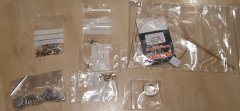
From the album: SSM GSR 800 / CIE B1a 4-6-0 etches
Castings, turnings, resin boiler / firebox joint, sundries -
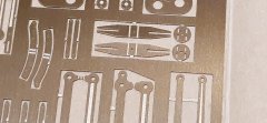
From the album: SSM GSR 800 / CIE B1a 4-6-0 etches
Close-up of valve guides, expansion links -
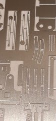
From the album: SSM GSR 800 / CIE B1a 4-6-0 etches
Close-up of expansion links, radius rods -
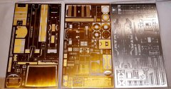
From the album: SSM GSR 800 / CIE B1a 4-6-0 etches
Locomotive body and chassis etches -
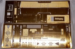
From the album: SSM GSR 800 / CIE B1a 4-6-0 etches
Tender etches -
I wonder what the GSR / CIE standard sleeper dimension was? 8ft 6in or 9ft?
-
If only there was a way of harnessing the wind generated by politicians....
-
I wonder if the 08 could be re-engineered to Euro6 standards
-
Ernies Massive Irish 1930's to 2005 Photo Archive
Horsetan replied to Glenderg's topic in Photos & Videos of the Prototype
That's likely to be Tailte's tender if the date is correct. The engine portion was long gone, but the tender did hang around for quite a long time after. -
I'll make a note. It's really Maedb's valve gear that fascinates me. It's Walschaerts' but with quite a few extra links thrown in, and only some of those are for the lubricator drive.
-
If it's any consolation, some branches of W.H Smith seem to think that Model Railway Journal is a top-shelf publication
-
That's just after triggering a memory of: "The town of Naas Is a terrible place; Kilcock was just as bad, But of all the towns I was ever in, **** me, Kinnegad....."


