Angus
-
Posts
301 -
Joined
-
Last visited
-
Days Won
3
Content Type
Profiles
Forums
Events
Gallery
Blogs
Everything posted by Angus
-
Thanks Ken, I'm just happy to be doing your design work justice. I've been pondering how best to build the fleet of SLNCR cattle wagons I will need. I didn't fancy scratch building multiple vans so have been reading up on resin casting, however I'm now convinced that 3d printing is the way to go (certainly for small scales anyway). I just need to get on with it!
-
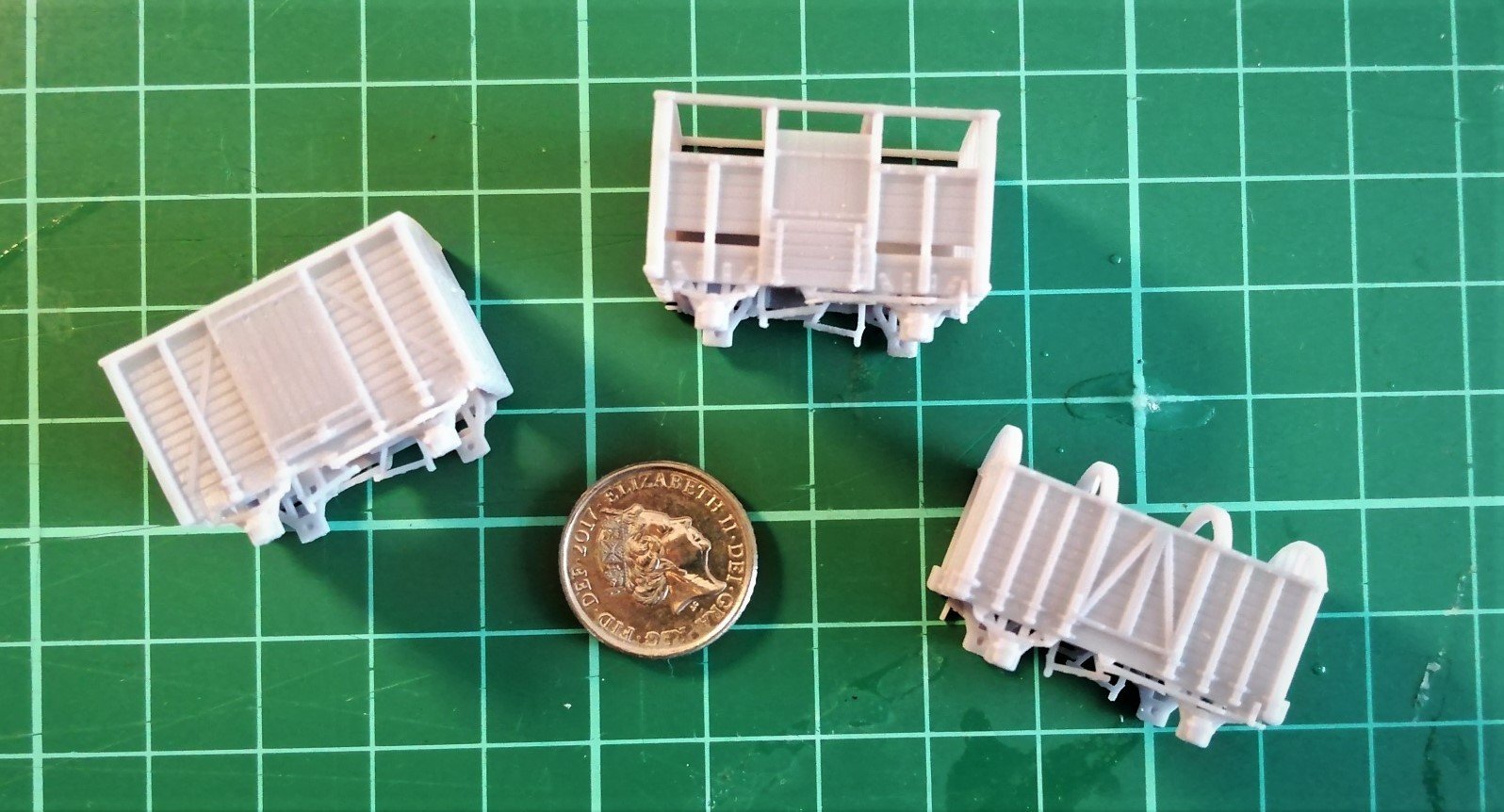
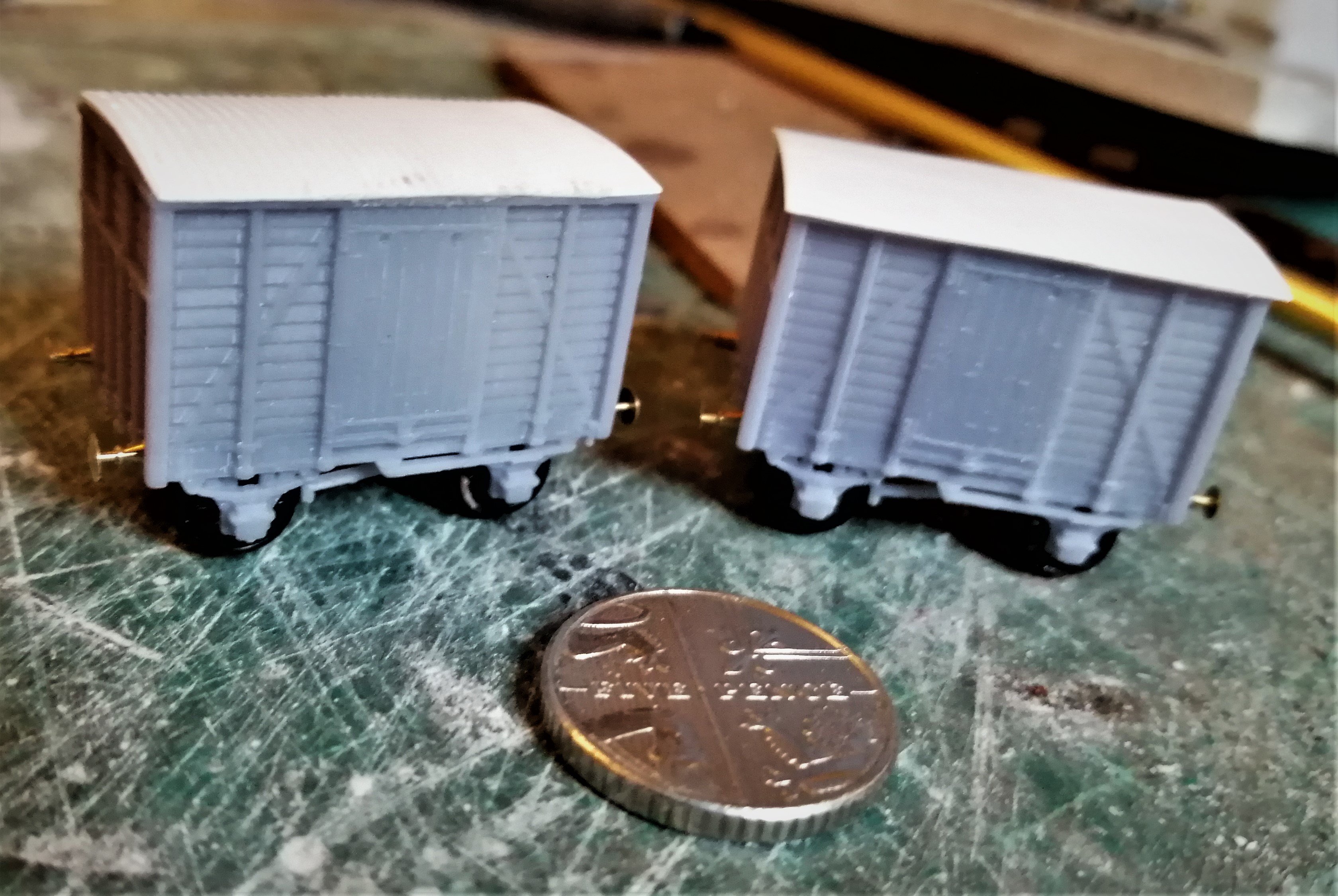
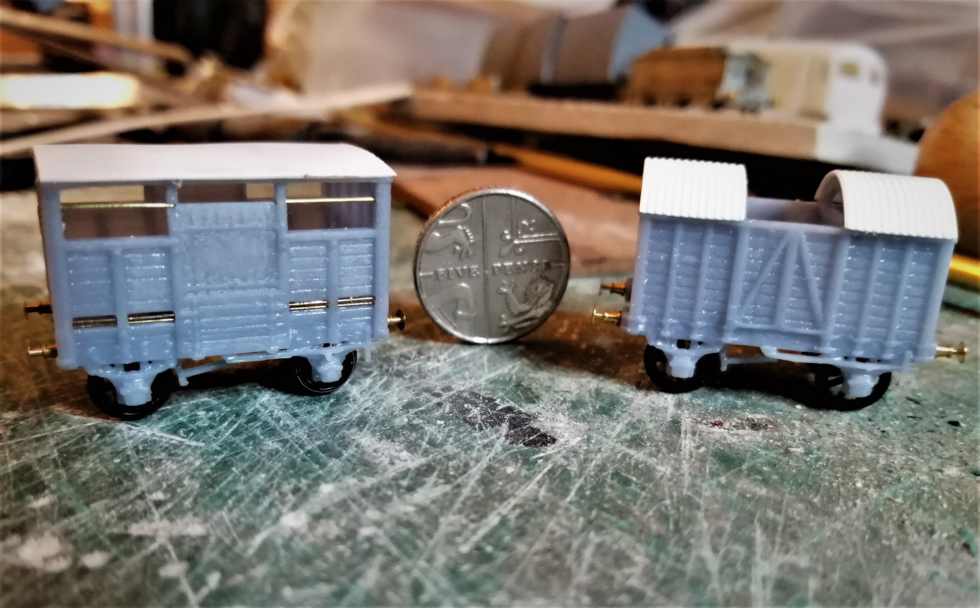
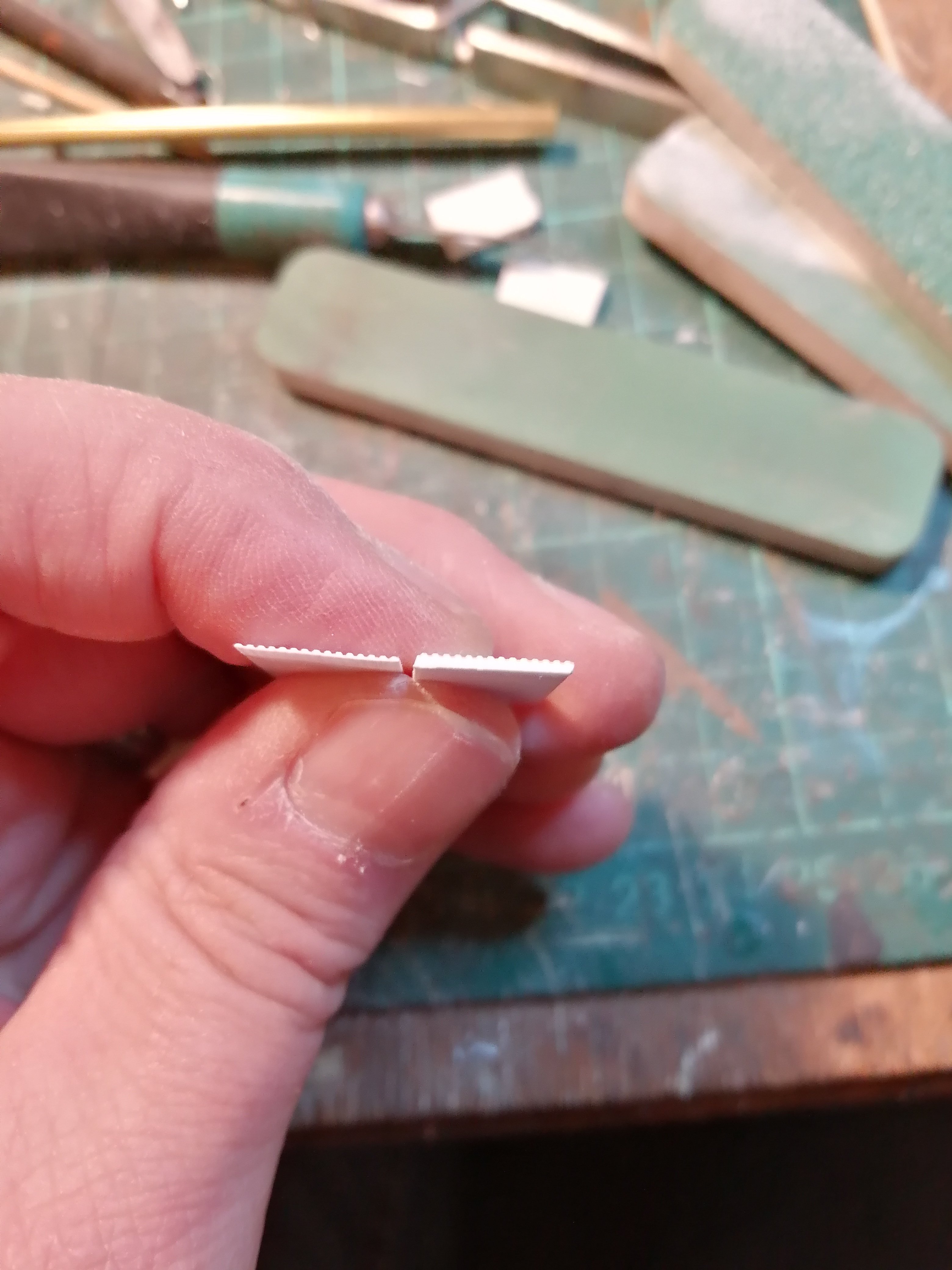
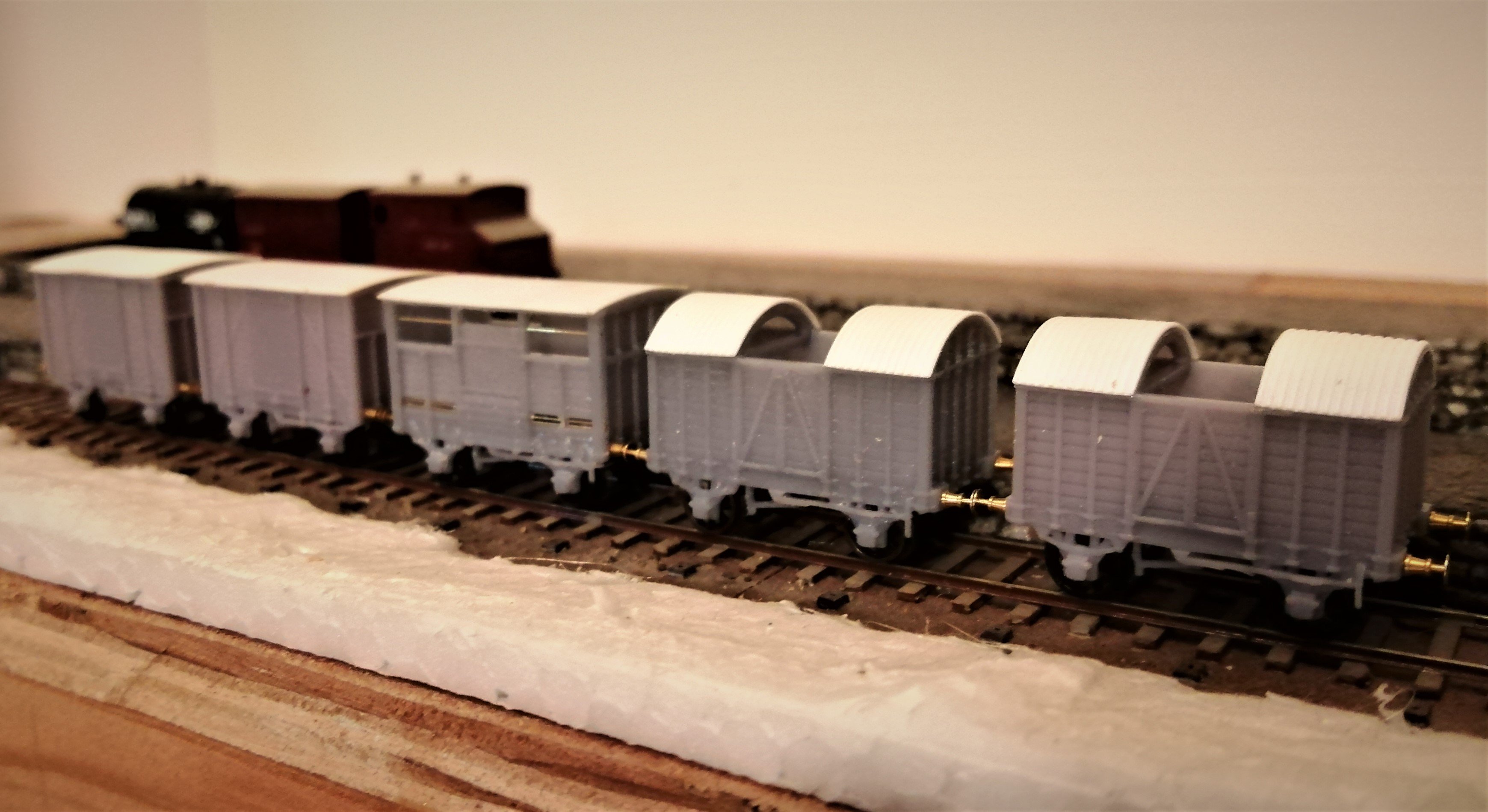
As I've mentioned in his work bench topic I reached a deal with KMCE to send me some his 3d printed 4mm Vans scaled down to 2mm. The Postie arrived with these gems on Wednesday: Unfortunately work commitments got in the way of playing, other than taking them out of the box, but with a free(ish) weekend thanks to the weather I spent some time at the bench getting the vans ready for painting. For the short wheel base vans I've used the photos in Rail to Achill as a guide, the vans are slightly different to those photographed but I've followed them anyway so one has a corrugated roof and split spoked wheels whilst the other has plain roof and plain spoked wheels. Apologies for the poor images, it's been hard getting enough light on the models, the white rooves don't help with focusing either. As an aside, were the corrugated rooves painted, or just left as plain galvanised sheet? It would seem a bit pointless to paint them. I'm pleased with the bars on the cattle truck, KMCE has printed dimples to locate the drill holes which makes drilling them and fitting the bars a doddle, the top bar is 0.3mm and the bottom two 0.2mm For the corrugated rooves I pondered a bit, I thought about using silver foil formed on a corrugated sheet but figured this would easily prone to damage. In the end I just thinned down some corrugated plastic sheet I had to hand, it was about 2mm thick so need thinning right down to bend to the curve of the roof and look the part. The corrugation are a bit wide mind. I need to work out how to make the canvas covers for the middle, I've previously used a technique described by Gordon Gravett in an edition of MRJ a few years back for some 7mm scale wagon tarps, I'm just struggling to lay my hands on the copy. All told I pleased with result, I might add a bit more detailing, some of the rivet detail is a bit lost (this is 2mm scale so asking a bit much of the printer to produce full rivet detail) which I might add using rivet transfers, and there are some grab handles to add but a couple of afternoon's work to produce five wagons gives my Irish Stock a much need boost. If I was building these from a kit or scratch I doubt I'd be half way through the first van by now. I was worried this might feel a bit too much like "open the box" modelling, but there was enough to do to make it interesting. I'm definitely sold on 3d printing now (even if does mean re-learning CAD), I just need to save my pennies. I've still another cattle van to do but have run out of wheels, so that will have to wait for another day. Just need source some decals now.

-
I think I may have caused some confusion with my top comment so I had best elaborate, Ken sold me some of his 3D printed vans scaled down to 2mm scale. They arrived mid-week so I've not had chance to do anything with them yet. There's snow on the ground here so my cancelled bike ride tomorrow may allow time to play.
-
They almost look as nice as the 2mm scale ones Ken
-
Ernies Massive Irish 1930's to 2005 Photo Archive
Angus replied to Glenderg's topic in Photos & Videos of the Prototype
A quick look through Neil Sprinks's Irish Railway Pictorial of the SL&NCR shows a surprising number of these "to run passenger trains" boards once you know to look for them. In most of the shots with cattle vans there are at least one or two vans that have the boards. There is a photo of the 7.20Pm mixed from 1950 on page 23 of the book where the first four cattle wagons have the boards. Definitely a nice detail to include (once I get around to modelling some of the wagons!). -
Ernies Massive Irish 1930's to 2005 Photo Archive
Angus replied to Glenderg's topic in Photos & Videos of the Prototype
Well that's at least two cattle wagons with them on then. I seem to recall that quite a few of the SLCNR cattle vans were vacuum braked. I'll have to spend some time trawling the photos. -
Ernies Massive Irish 1930's to 2005 Photo Archive
Angus replied to Glenderg's topic in Photos & Videos of the Prototype
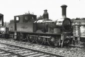
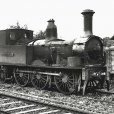
and it gives a great unobstructed view of the bunker, a useful reference for modelling. Also I not seen the "to run with passenger trains" board on the cattle wagon before, were these common? I can't see any on the rest of the rake. I have seen the wording on other MGWR Non-passenger stock (Horse Boxes, Meat Vans etc,) -
Thanks Jaz, I moved my stock build over to a thread in the "workbench" section as Dromahair is being built as a small module for a specific competition in July 2022 and will probably have a limited life as a result, although the intention is that some of the structures may live on in a later layout. The stock build thread is here, albeit I'm embarrassed to find I haven't posted anything since mid July. I tend to model in fits and starts and I can feel the start of my next modelling fit coming on...... I've already started on a C class (first post on that shortly) and I'm on my third attempt at the Dromahair Station building. The first two weren't right so abandoned (Gable ends to narrow, then windows set too low......third time lucky!)
-
Thanks J-Mo, I need to get my finger out and get some more modelling done. I've been dabbling of late and not really making any forward progress. Hopefully the winter months will help!
-
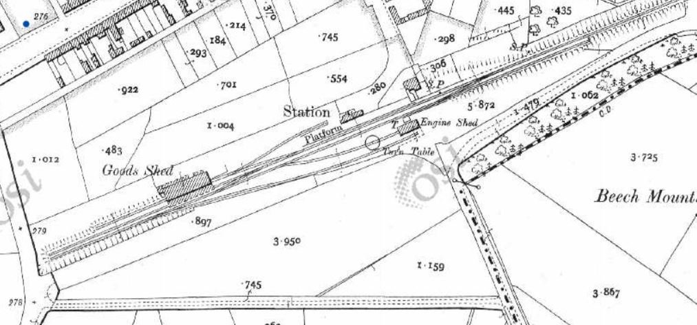
Below is a screen shot from the Government of Ireland's Historic Environment viewer 25" to the mile map. I've found the accuracy of the outline of the buildings a bit dubious on other maps, I can't comment on this one. This link should take you the map: https://maps.archaeology.ie/historicenvironment/?REG_NO=30806021 It doesn't! For some reason it takes you to Dromahair ( my saved location). If you click the four squares Icon on the top left you can select historic 25" to the mile as the base map, the just enter "Ballaghadereen" in the search. You'll need to select the correct locality from the search drop down. Hope that helps!
-
I think you've managed to sum my whole modelling life in a line there! Ah! the true way, pure and unblemished! I admire your focus, I would always be tempted by other lines. Out of interest have you managed to source some drawings or are you working from photos? Black Lion is look great!
-
Be careful with Bookdepoistory, they don't always stock the books they advertise. I tried to buy the recent GSWR loco book through them after they came up on a Google search offering a discount. I paid for the book only to wait and wait for it to come into stock. After a few enquiries on here it became apparent that the book was only available direct from the publishers. I challenged Bookdepository and they were adamant they were just awaiting stock. Once requested they did provide a refund though.
-
Self propelled cranes and small coasters
Angus replied to David Holman's question in Questions & Answers
yes, the fully lined versions predate Hermes and UPS -
That's very evocative and captures the creature of the prototype very well. Lovely modelling Galteemore!
-
Ernies Massive Irish 1930's to 2005 Photo Archive
Angus replied to Glenderg's topic in Photos & Videos of the Prototype
It's probably been commented on before but aren't the tablet catchers the wrong way round on the B class? It would need a man riding in the rear cab to collect the tablet as well as the driver in the front. Seems a bit odd, any reason why they were used like that? -
Thanks Galteemore, I have the link to that site in my favourites, one thing to watch is that they use a couple of different spellings of Dromahair, wading through the pictures reveals a few more of the station.
-
I'll look forward to seeing that Galteemore, one can never have enough SLNCR!
-
Hi Galteemore, Measuring my platforms they are 52.5mm over the ramps so 105ft. That's a pretty round number so I guess I've approximated from the 25" to the mile OS map. There are some errors on the map, none of the building footprints tie in with reality, the platforms seem ok though. Hope that helps? Are we about to see a 7mm Dromahair break cover? Cheers Angus
-
Hi Ken, At the risk of diverting David's thread, I'm modelling to 10.5mm gauge so a simple scale down will work thanks
-
How about 2mm just to complete the set? If it were possible I'd be interested in a couple of prints, appreciating that this doesn't represent a good business case!
-
It's more a problem when you inhale.......
-
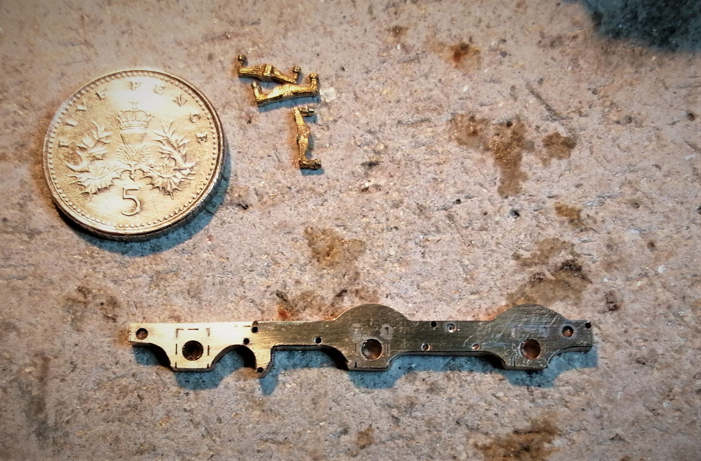
A productive day has been spent drilling out the chassis and cutting to shape. I did take a couple of photos of the process but either my camera or computer has managed to corrupt them. The chassis assembly in the post above was set up in the mill and the axle holes drilled to 0.5mm then 1.0mm and finally 1.5mm before being reamed, the reamer didn't seem to take any material so I suspect my 1.5mm drill is slightly oversize. I then drilled out the brake holes, I tried using a 0.3mm carbide drill but manged to break this in the frame (I really cannot get on with these drills!). As my HSS 0.2mm drill was too short to drill through 1.7mm of the frames plus etch I reverted to the 0.5mm diameter. The holes will slightly oversize, but not seen behind the brakes. I also had to re-drill under the snapped drill so this will be slightly out of line, but again hidden under the brake gear. The frames was then roughly cut to shape with a piercing saw, I am always amazed how quick this is now I've learnt some proper technique, I only broke one blade in the process and that through stupidity. After attacking them with some files I've a presentable pair of frames. They just need separating and cleaning up. The chassis assembly can then commence. Three of the tender springs are photobombing the picture, I must get them soldered in!
-
0.5mm shanked drills are available from Proxxon at reasonable prices and also quality German and Swiss 0.5mm drills can also be found via the Jewellery tool supplier Cousins UK and Cookson Gold. I have some Seiko drills in the 0.2 to 0.3mm range that appear on Ebay from time to time price is around £25 for a box of ten. Other than that there are plenty of straight shanked drills available, I just find handling them a bit of a pain once they get down to the smaller diameters. You also need a decent quality pin chuck to hold them. I also use some three side micro broaches from Bergeon for adjusting very small holes to size
-
One thing that helps is to make sure you are using HSS bits (I prefer the shanked variety) and not the tungsten carbide bits widely (and cheaply) available on ebay and other outlets The tungsten carbide bits are very brittle and aggressively fluted so break really easy. The HSS ones are more flexible and more tolerant of use and abuse.
-
Thanks both for the advice. I'll look at adding the ashpan. I was planning to incorporate this as a separate layer behind the frames to give some depth. Although given the frames are a scale 4.5" thick that might be too much relief. I've considered a RSU on several occasions David, more for my 7mm modelling though. I see the benefits there, particularly when soldering overlays onto large chunks of brass. For the finer 2mm stuff I would be worried about the vaporisation effect, some of the metal thickness used are wafer thin. There is also the faff factor. A unit would be too big to keep out on the workbench so would need to be unpacked and put away each session whereas a soldering iron just sits at the side waiting to be switched on. Most of my problems occur from rushing and not clamping firmly and using heat sinks. I am getting better though! For the tender brake gear I am not going to use the items from the etch. Trying to make up the separate components would be too taxing. Instead I have some etched brake shoes complete with arms purchased from the Worsley Works scrap box at a show. I am hoping these will make life simpler.