David Holman
-
Posts
4,359 -
Joined
-
Last visited
-
Days Won
117
Content Type
Profiles
Forums
Events
Gallery
Blogs
Community Map
Everything posted by David Holman
-
Gauge of interest: Alphagraphix 4mm Irish kits
David Holman replied to GSR 800's topic in Irish Models
Roger's 7mm scale kits feature a one piece etched chassis. Have mentioned before that you solder in the bearings, then simply fold the sides and spacers. They are designed for 32mm gauge, so you fit the top hat bearings inside out for broad gauge. Never had any problems with clearances for splashers and other bodywork, so presume things should be ok in 4mm. However, if there are no castings, what you will get is the same as with Worsley Works, so that means sourcing or making everything from chimney, dome, buffers, cab details, whistle tender axle boxes, brake standard, etc, etc. Without wanting to rain on anyone's parade, finding such things is a lot harder now than it was ten or even 20 years ago, when there were many more whitemetal and brass castings available, though 3D printed options may be possible now. -
Starting halfway down page 27 of David's Work bench is a step by step account of how I made the Alphagraphix J26.
- 54 replies
-
- 1
-

-
- o gauge layout
- irish outline
- (and 2 more)
-
Interesting not-so-early Irish Railway photos
David Holman replied to Mol_PMB's topic in General Chat
Interesting to read that bits of Sprite linger on in No 90. Have often tinkered with the idea of building Sprite and its pay coach, because they travelled far and wide in their time and would make a novel addition to my 1900s scenes on Northport Quay. Thus far have only got round to making an outline drawing, using info in the Green Bible, but if anyone has anything else, it might just be the nudge I need... -
"Voiding the Warranty" - Mol's experiments in 21mm gauge
David Holman replied to Mol_PMB's topic in Irish Models
Last photo looks a great place to work from. As for mixing co!ours too dark or bright, got lots of t-shirts in that drawer! -
The Alphagraphix J26 is pretty simple, especially the chassis. It's a single etch, so you just solder in the wheel bearings before folding up the sides and folding down the frame spacers. No alignment jobs required. I've built two and you can have a rolling chassis in a couple of hours. Very satisfying and very effective.
- 54 replies
-
- 5
-

-

-
- o gauge layout
- irish outline
- (and 2 more)
-
They can work out very expensive, so consider buying a large sheet of acrylic and make your own.
-
"Voiding the Warranty" - Mol's experiments in 21mm gauge
David Holman replied to Mol_PMB's topic in Irish Models
A thought: the sky is very dark, especially when compared to the near white of the prototype scene, or are you going for twilight? That said, earlier pics with the trees posed in front it appears less so. -
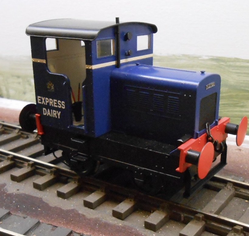
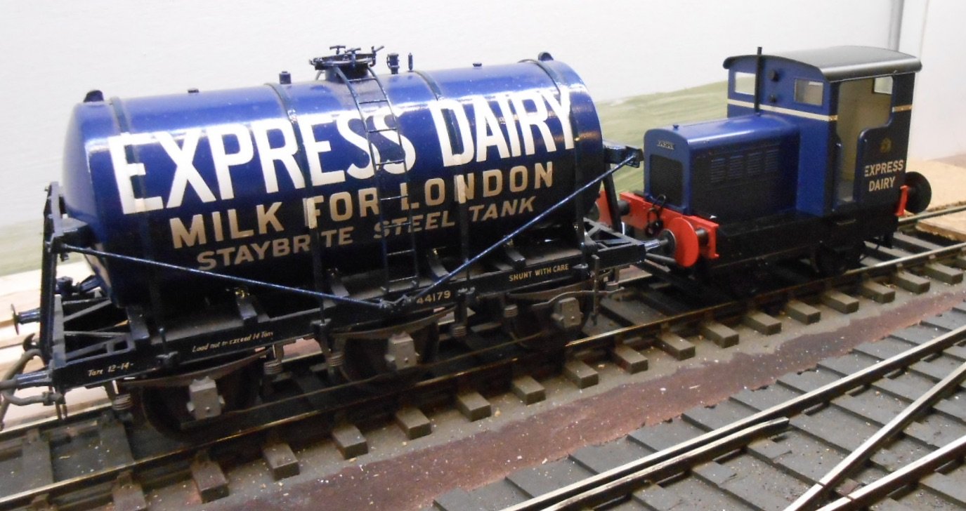
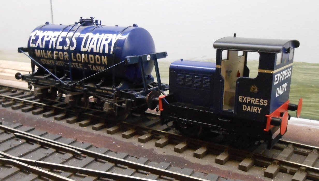
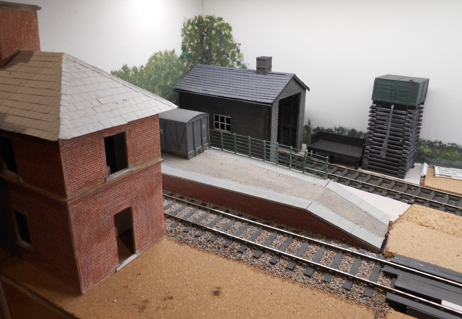
I actually bought a ready to run, 0 gauge engine this week - a rare occurrence for me. indeed, had to look up my journals to see when the last time was. Turns out that was in 2010 & even then it was a couple of Bachmann Brassworks models [08 shunter and Derby Lightweight DMU], which required painting and detailing, so certainly not rtr in the accepted sense. The same year, I also bought a couple of Shays, one a two truck 0n16.5, the other an HO three truck and these were fully finished. Otherwise, have to back to the 1980s and everything else has since been kit or scratch built - a total of 75 locos to date. So, you ask, what is it that prompted this extravagance? Well, it's about as small as it gets in 0 gauge: a Heljan Ruston 48 DS and very dinky it is too. Needs work, as far too clean for my liking, while also crew and [eventually] AJ couplings. The version I've bought fits in with the aim of there being a dairy on my new project and the Ruston fits the bill nicely as I already have three six wheel milk tanks, one [a Slaters kit] in full Express Dairy livery. A bit more work has been done on the layout, with the station master's house now well under way. The 'chassis' is mounting board, covered with Howard Scenics embossed brick paper. Back in the last century, I used to paint all the bricks individually, until sanity prevailed when I realised I could do it far quicker with water colour pencil crayons. Windows will be from York Models.

-
Good way to increase a layout's usefulness. Should I ask how you are going to widen the track?
- 54 replies
-
- 2
-

-
-
- o gauge layout
- irish outline
- (and 2 more)
-
That is a beauty.
-
Must be very deep pile carpet! Fine work Alan.
-
"Voiding the Warranty" - Mol's experiments in 21mm gauge
David Holman replied to Mol_PMB's topic in Irish Models
Can only agree with the comments above. Lovely stuff. -
Fine work John and certainly looks well worth it.
-
Two fine 4-4-0s!
-
Will be a very good place for photographs.
-
Forward thinking seems to be very much part of the project. It is estimated it will cost at least two million and they are hoping that the time scale will encourage 'ownership' as like GSWR90 says those involved mature with the engine. Only time will tell.
-
In the latest Railway Magazine is a short article about a new build loco, of all things a Midland & Great Northern 4-4-0. They reckon it will be a 20 year project. One of the reasons for choosing it, apart from being a very pretty engine, is its small size should make it economical to run, including a firebox designed to use ovoids. Certainly nothing if not ambitious!
-
"Voiding the Warranty" - Mol's experiments in 21mm gauge
David Holman replied to Mol_PMB's topic in Irish Models
Those shutters will be a lot easier to model than window frames! -
Certainly looks like 20 could only be turned in one direction. Nice collection of fishing boats too. Something else to add to the list.
-
A fine ensemble. There is something rather nice about a mixed take of vehicles and certainly more interesting than a fixed unit railcard set...
-
"Voiding the Warranty" - Mol's experiments in 21mm gauge
David Holman replied to Mol_PMB's topic in Irish Models
Lovely stuff and coming on a treat. -
The itch to raid the scrap box is getting stronger...
-
"Voiding the Warranty" - Mol's experiments in 21mm gauge
David Holman replied to Mol_PMB's topic in Irish Models
Google photos of the Rathmelton quayside show red doors, with very peeling paint, suggesting it had been that colour for quite a while. Indeed, enlarging your photos shows the same. They also show it's not exactly the finest stone that's been used. Rubble would be a better description and even the brickwork around the openings looks decidedly second hand! All adds to the charm, of course and some talc to texture the paint might not go amiss. -
It is indeed, Leslie. Booked over a year ago when the name hadn't been finalised. Guess I'd better let them know...
-
Working dioramas rule. Everybody should have (at least) one!