David Holman
-
Posts
4,359 -
Joined
-
Last visited
-
Days Won
117
Content Type
Profiles
Forums
Events
Gallery
Blogs
Everything posted by David Holman
-
Quite a variety! Not sure, but is the box like thing by the balcony steps an acetylene generator? They were an alternative lighting. Some sort of chemical reaction to produce the gas & you can see a pipe going up to the roof, next to the handrail.
-
Simple, well fairly, but very effective!
-
Have seen two Lartigue layouts. One was a simple oval at, I think, the Uckfield show. Amazing to see a loco and train wobble its way by. The other was an embryonic layout at the St Albans show, where the owner was demonstrating fabulous etched trackwork. Don't know what became of this, but it certainly looked promising.
-
Just when you think you've seen all of Andy's layouts... Great way to display all his wonderful Donegal stock.
-
Ok, not exactly Irish, but Blakey Rigg, the S Gauge NER layout by Paul Greene of this parish features in the latest Model Railway Journal. Indeed, it is a remarkable issue featuring a working 1:400 scale (yes, really) working model railway. Add in articles on DG couplings, realistic moving road vehicles in smaller scales and preview pictures of Gordon Gravett's new French layout and it adds up to being well worth a look.
-
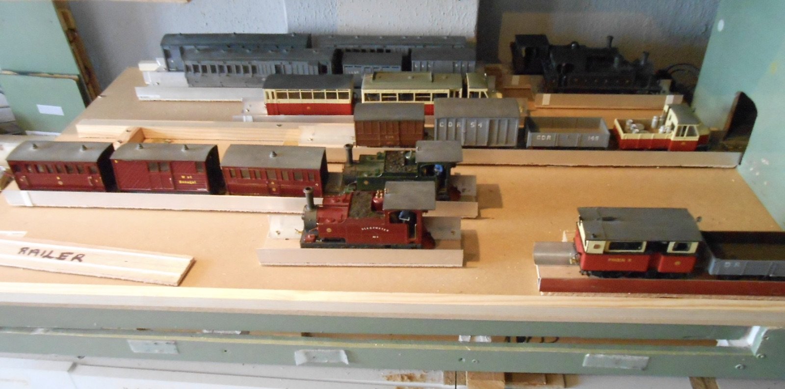
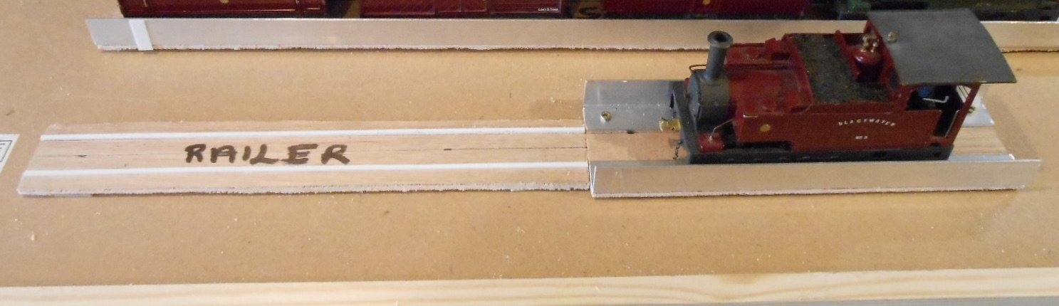
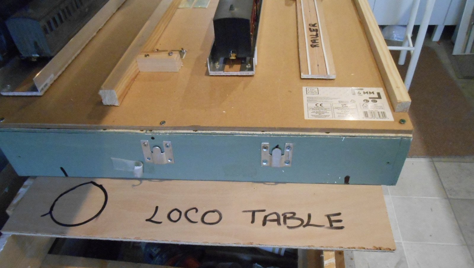
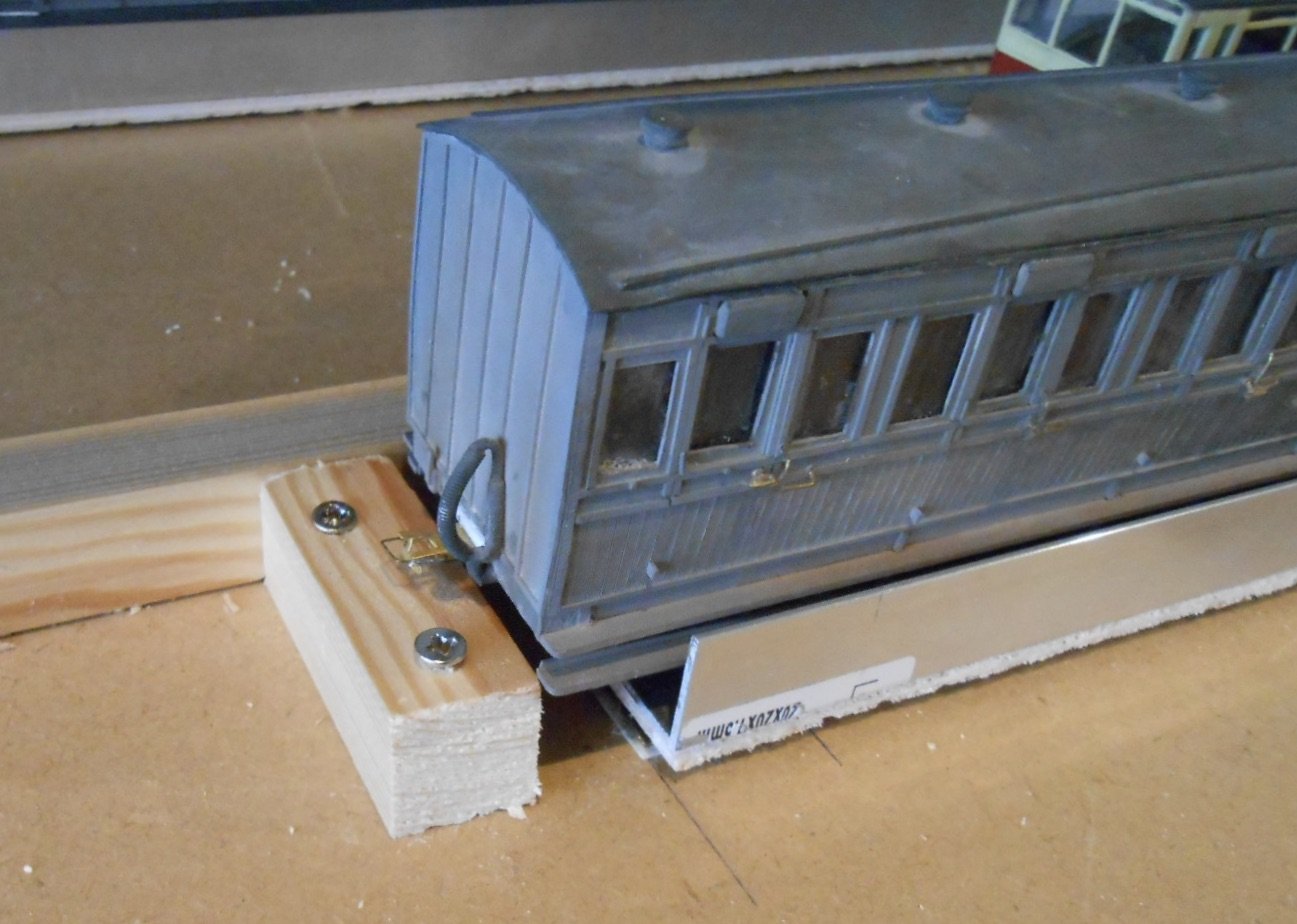
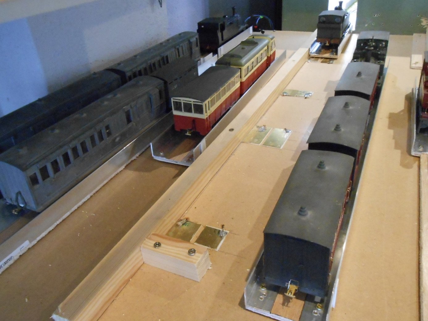
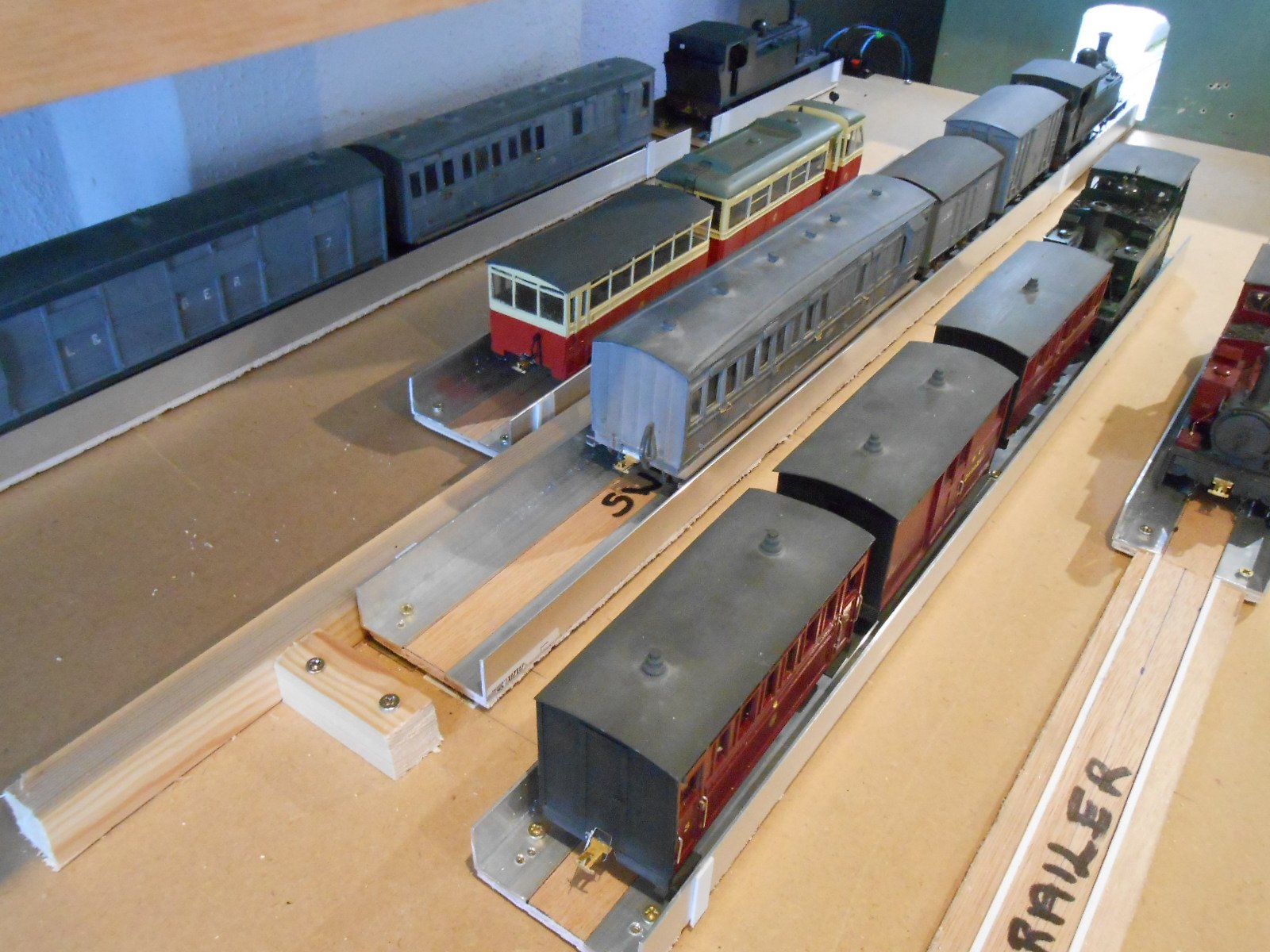
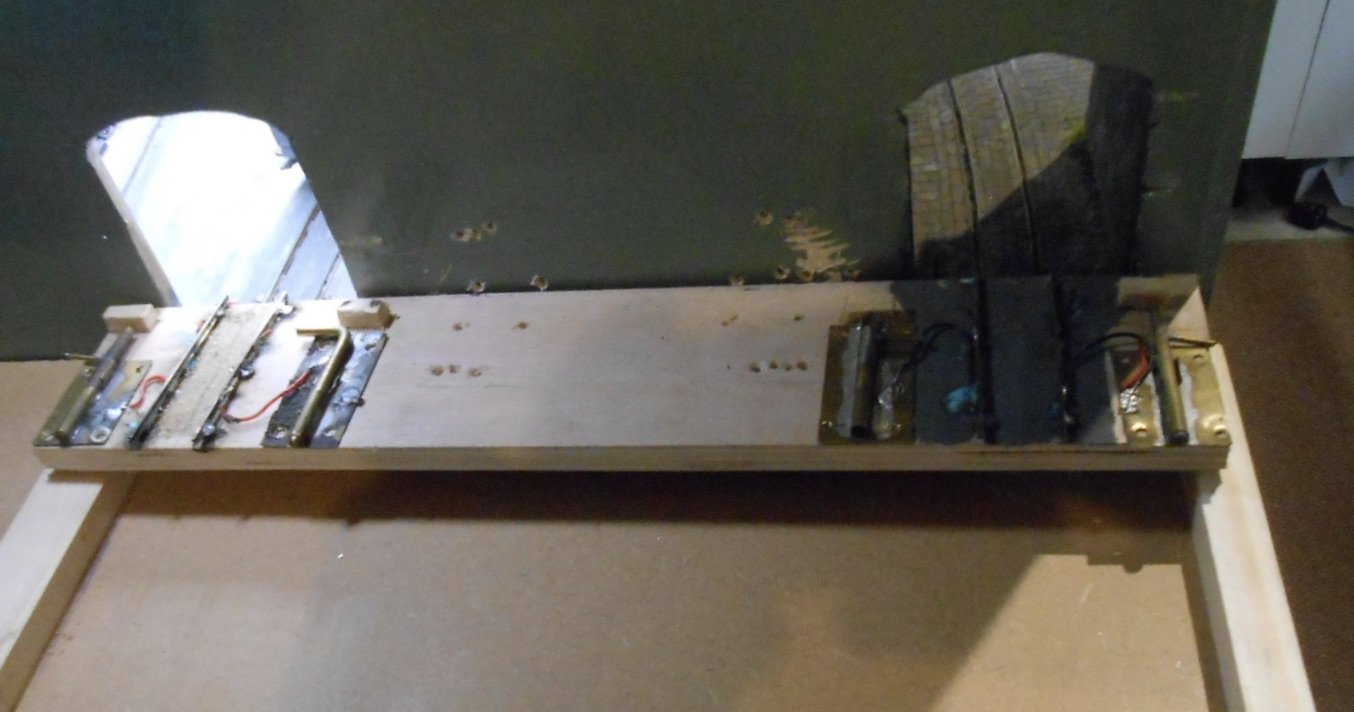
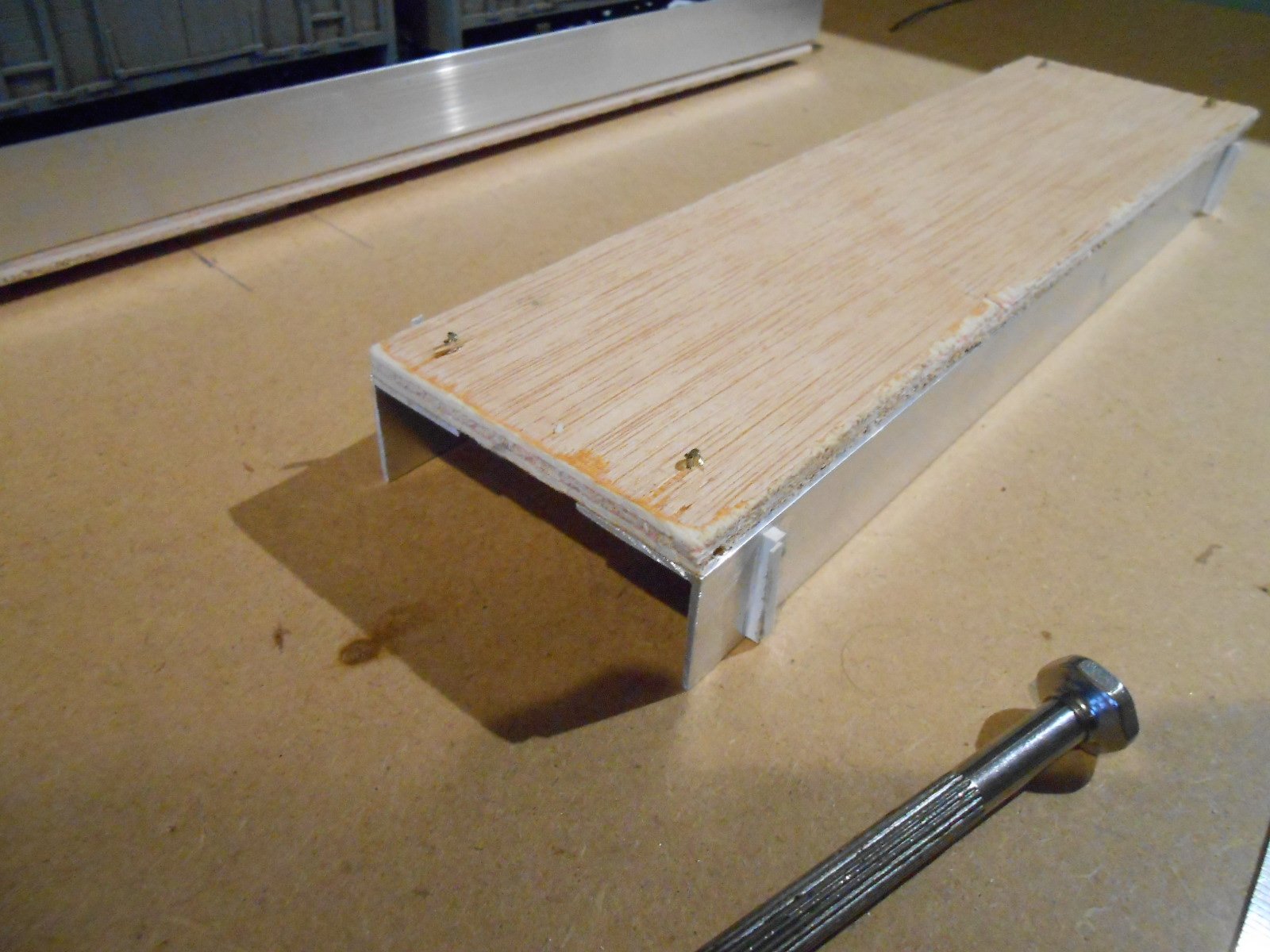
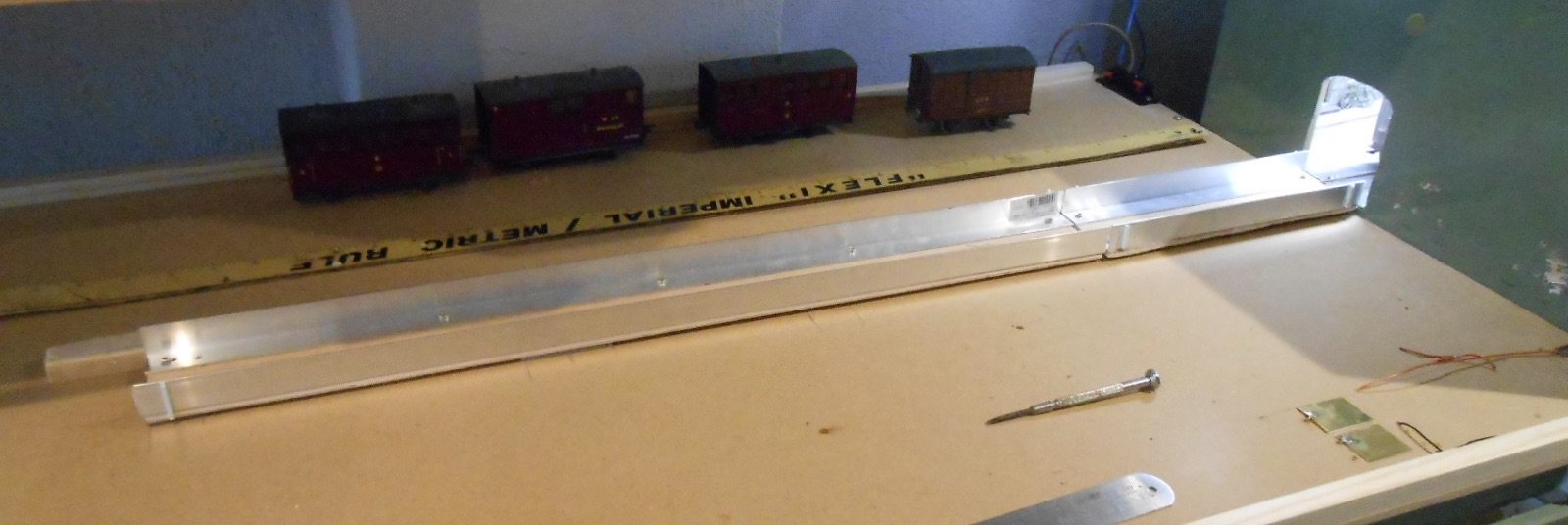
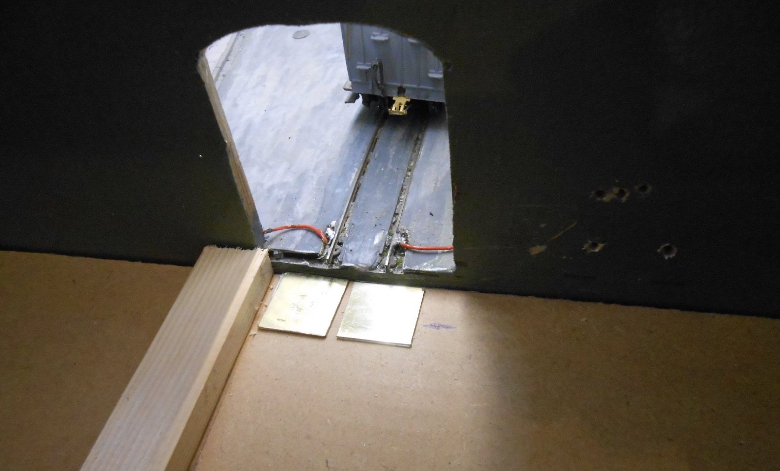
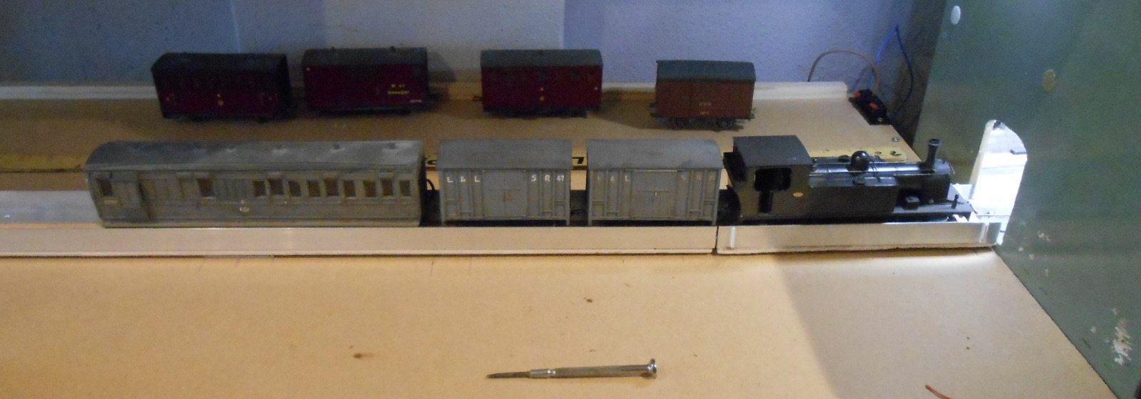
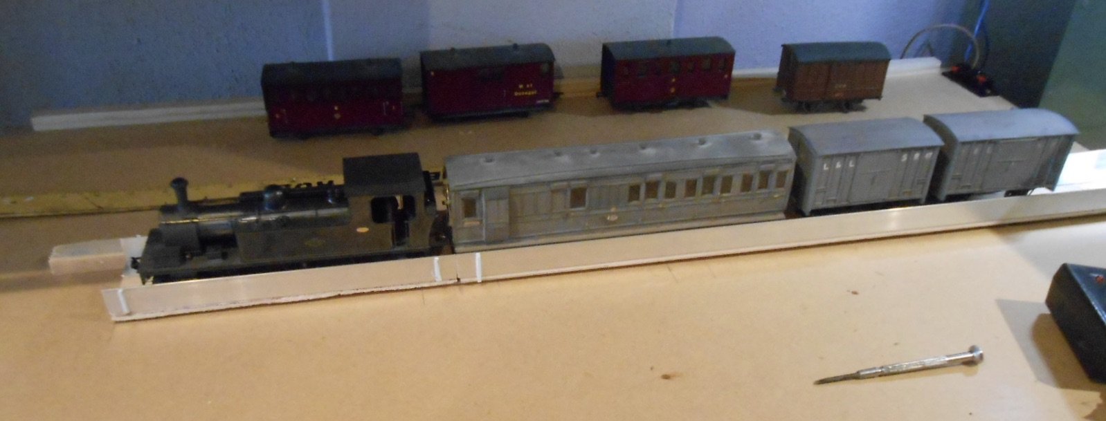
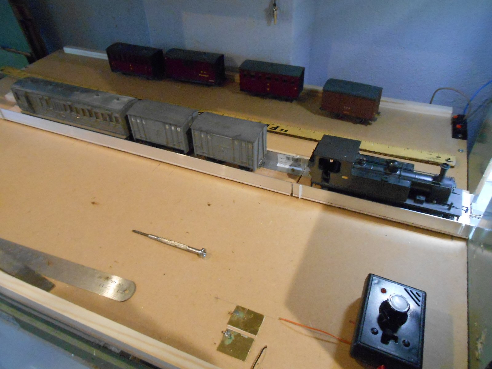
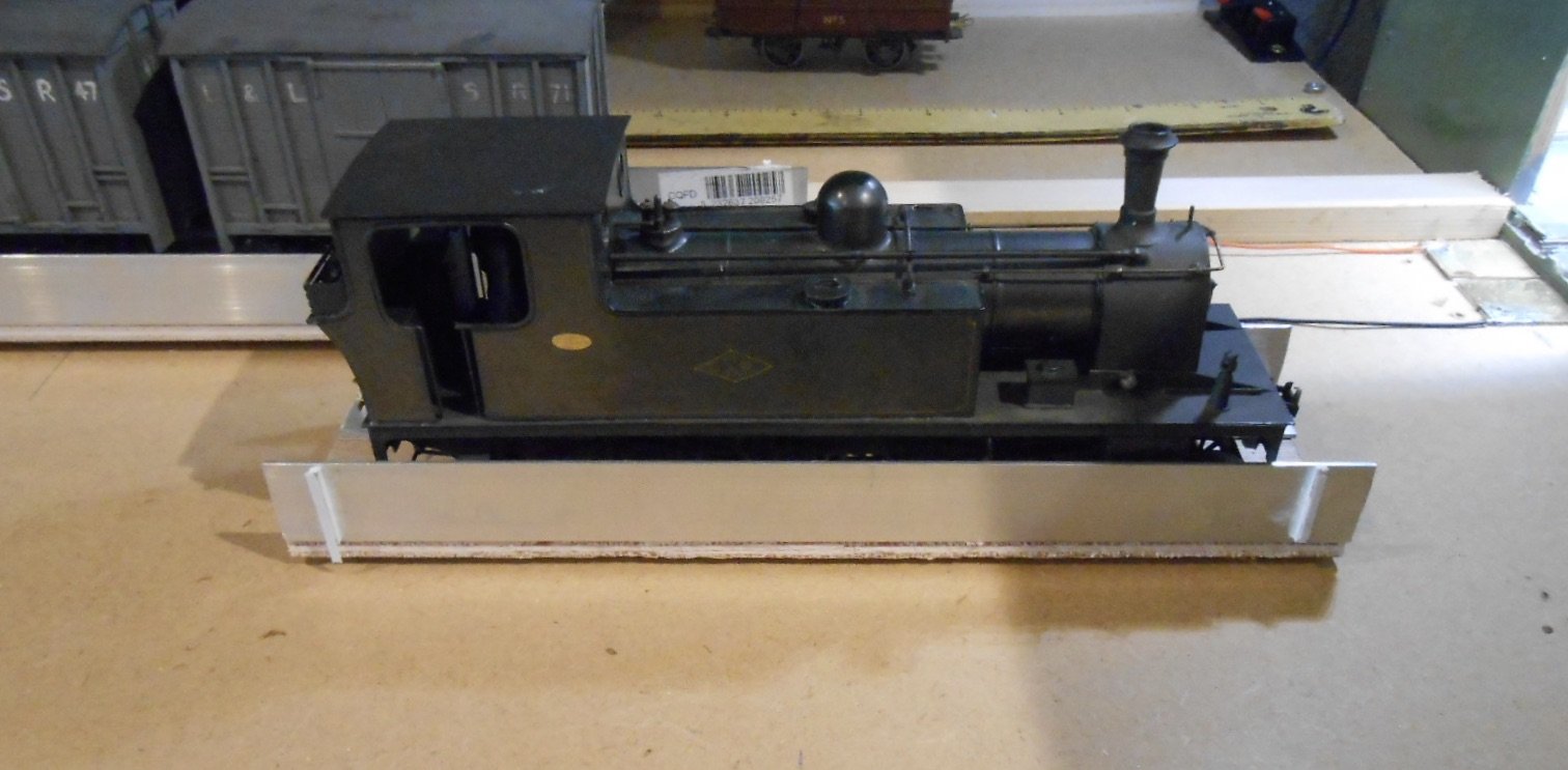
Much time has been spent this week fine tuning the cassettes and fiddle yard table. Above you can see the five trains, spare engine, plus Phoenix and its wagon cassette. I was expecting a bit of work because experience with Fintonagh taught me that if the back to backs are more than 0.2mm out, then derailments are possible on the points and so it proved. Horizontal alignment is achieved by glueing plasticard strip to the vertical wall of each cassette. Mostly this has been 40 thou/one millimetre thickness, but occasionally, only 20 thou has been needed and in one case 60 thou [20+40]. Vertical alignment is really just careful filing of the fixing screws. Occasionally, I found I'd taken too much off and a fresh screw was needed. Also managed to fix one or two screws too far inboard, meaning bogies, axle boxes etc could clout them. Needless to say, this brought out more than a bit of creative bad language, but only myself to blame. Quickly realised that a different cassette was going to be needed - one without any sides to make railing stock easier. Narrow gauge vehicles are hard enough at the best of times, with their wide overhangs, but the cassette sides make putting on anything other than a four wheel vehicle pretty much impossible. My simple solution was to stick 60 x 100 plastic strip to a piece of plywood that has flat aluminium strip glued underneath. White plastic works well with dark wheels too. Though there is plenty of room on the cassette table, have found a piece of plywood pushed under the outer end of the table gives space to put a loco cassette while it is being turned. Doubles up as space for a coffee mug and nicely levels the cassette table too. An important safety item is this small block of wood, just beyond the end of where the main cassette goes - just in case a train should over run. The height is just right for the DG couplings to clear it. A couple of other pictures show how the train cassettes might be shuffled around. Otherwise, so far so good. Now need to work on rehearsing operation on the layout itself, while all the new couplings need to be checked and then chemically blackened.

-
Always interesting to see what you are working on Eoin. With an Athearn chassis, performance should be exponentially better than the prototype!
-
IRM is 10 This Weekend - Come See Us Where It All Began With SDMRC
David Holman replied to Warbonnet's topic in News
Yep, be VERY proud! -
"Voiding the Warranty" - Mol's experiments in 21mm gauge
David Holman replied to Mol_PMB's topic in Irish Models
Looking great. Am sure you'll find the switch rails easy enough once you made the first one. -
See that Tara Junction has just clocked up a million views!
-
Thanks Eoin and an interesting thought. I've kept all previous magazines that I've had articles in and it is nice to look back at them occasionally. Maybe I'll scan and reduce that cover, so it could go in a smaller frame.
-
Definitely coming to life and it is those fine details which help.
-
The trick is in the fine tuning, Mick. The plasticard strip on the aluminium angle vertical is just pushed against that strip of wood. If the cassette doesn't line up exactly and anything derails going to/from the layout, I add a bit more plasticard. Ten thou is just 0.25mm, so a bit of trial and error soon gets it sorted.
-
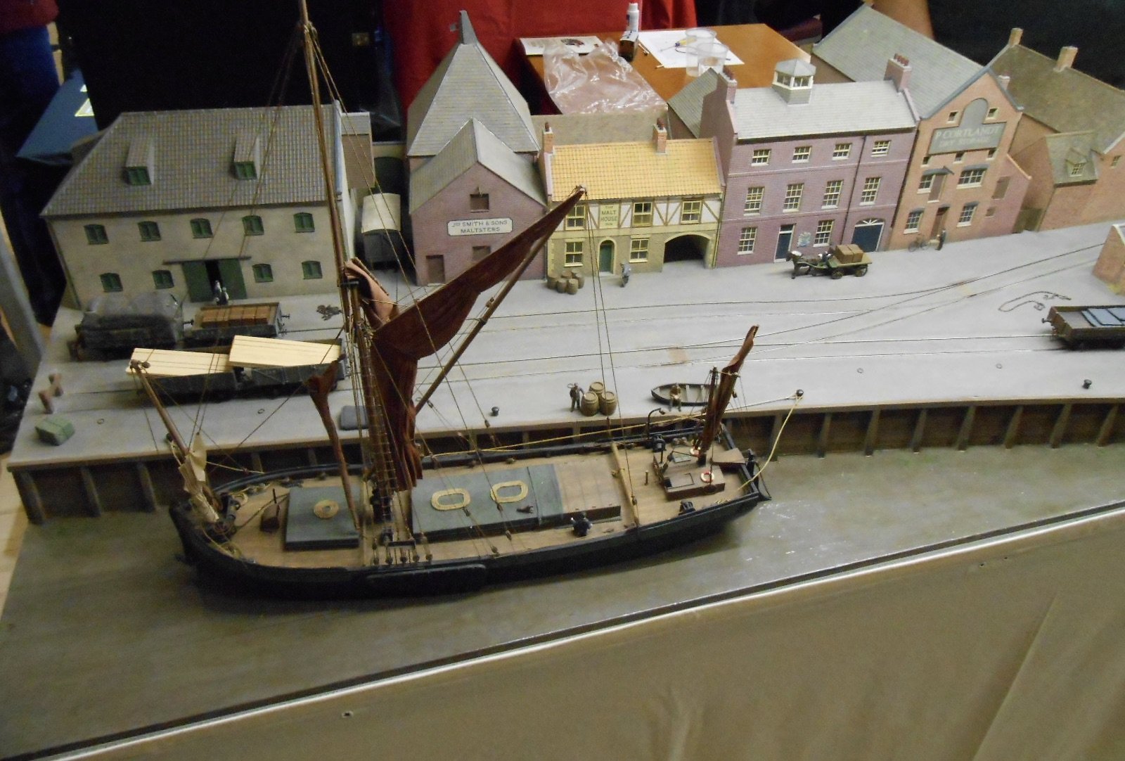
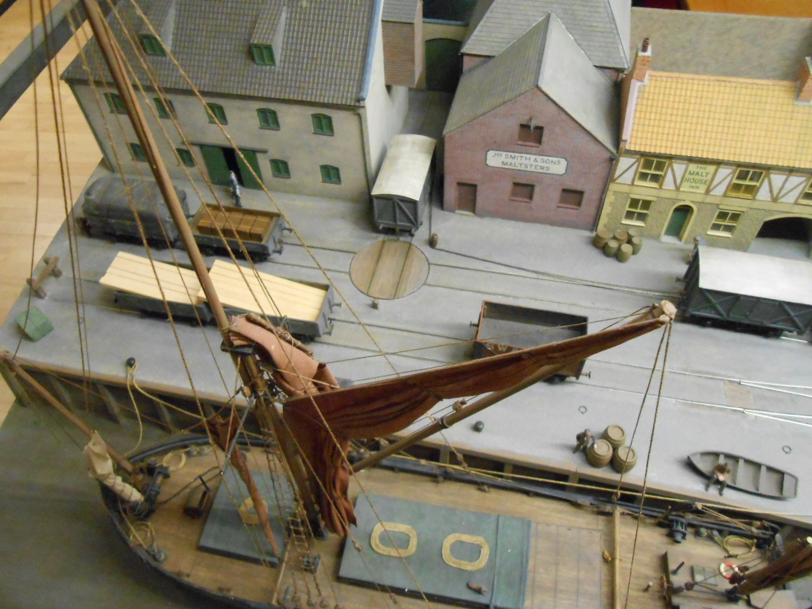
Was at the Uckfield Show this morning and delighted to find, amongst the usual range of superb layouts, a small portion of East Lynn. Trevor is sadly no longer with us, but it was lovely to see even this small section. S Gauge [1:64] and pretty much completely scratch built, East Lynn was a stunning portrayal of the Great Eastern & Midland Great Northern in pre-grouping days. The small quayside section was particularly special for me, because I had the privilege of operating it, twice, around 20 years ago. It features chain shunting, where you need to use suitably sited capstans to enable the loco to position wagons in all sorts of strange corners as seen below. The wagon turntable works too, while some of the stock here is now 50+ years old. The loco [out of shot], is pulling the wagon on to the turntable, with the chain, which goes on the coupling hooks. Feel free to add your your own memories of Ken's work.
- 5 replies
-
- 11
-

-

-
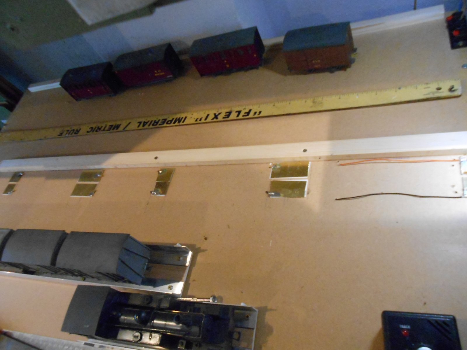
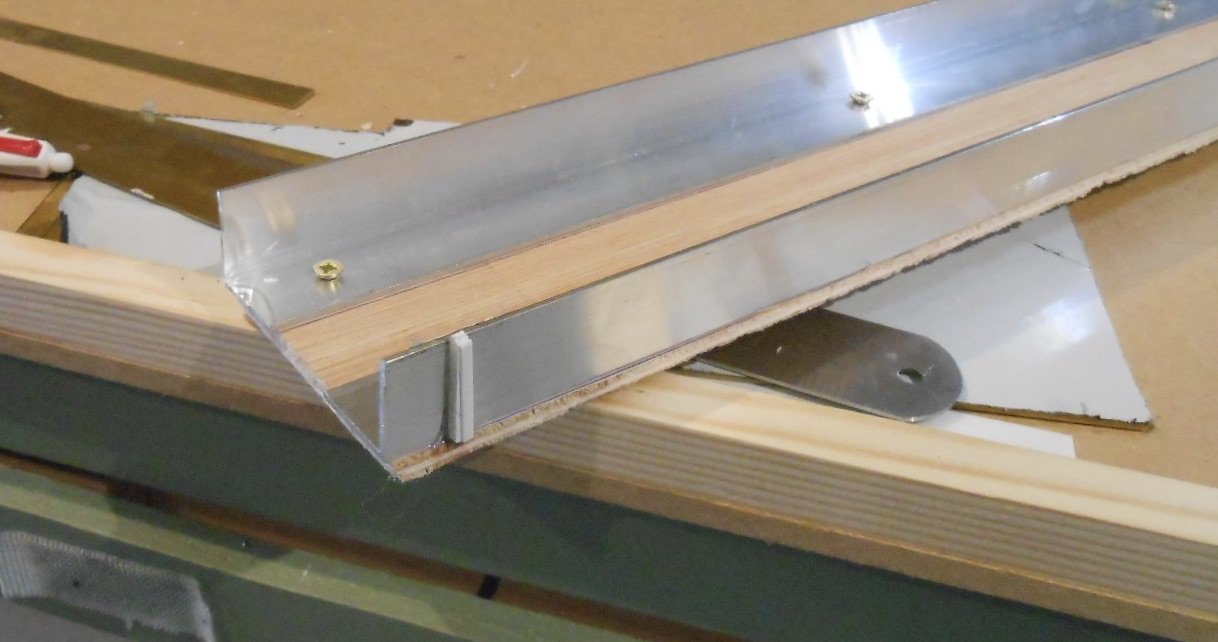
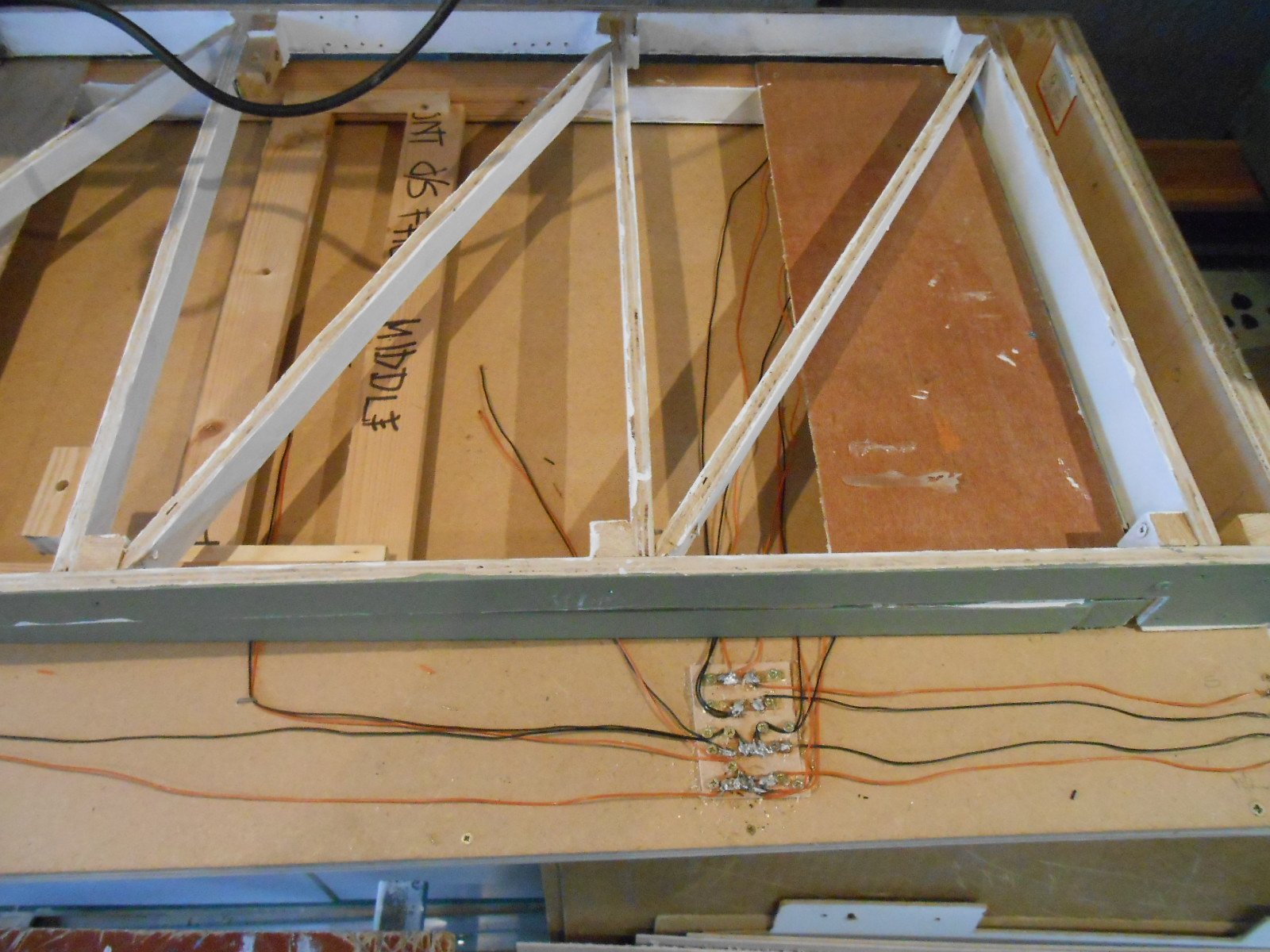
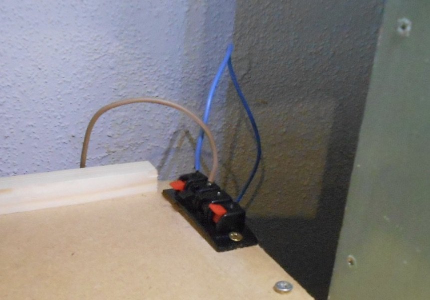
Cassettes I'd long had a feeling that my sliding/turntable fiddle yard for Northport Quay might not be completely compatible with Swillybegs and so it has proved. A slight discrepancy of height on the interface causes stock to uncouple - not good. Also, the short interface section between the train table and the layout means two joints in the space of 10cm AND on a gradient. So, what to do? After much thought, decided the best option was to remove the train table and fit a new top that could take cassettes instead. Cassettes are not a new idea, but my take on simple alignment and power may be of interest. The cassette table itself is just a piece of 6mm MDF, strengthened with a piece of softwood along each edge. Each cassette is a piece of 5.5mm plywood, with two 20mm L section aluminium angle pieces that act as the track. The angle is screwed to the plywood, though I also use double sided tape to position it initially. The clever [?] bit is that the screws project through the plywood, sticking out about 1.5mm the other side. Why? Because these screws carry the electric power, which comes via brass strip fitted at strategic points to the cassette table. Another piece of softwood is screwed to the cassette table and is used to align the cassette, as shown below. While two long pieces of brass strip could be used to span the full length of the cassette table, for economy, I use several smaller pieces, spaced to match the separate loco and train cassettes. This requires a bit of extra wiring, of course, but have found it works well in practice on a previous 0 gauge layout. Some cassettes [eg a railcar, or a short freight] are not difficult to pick up and turn round when the trains come back to the fiddle yard, so they are ready to be sent out again. Longer trains are better having separate loco and train cassettes, so just the loco has to be picked up, turned and moved to the other end. So, loco cassettes are 9" long, train cassettes are 24" and railcar [+ trailer] 18", equating to how the brass strips are spaced out. Vertical and horizontal alignment is fine tuned with pieces of plasticard. The brass strips sit on 20thou [0.5mm] plastic sheet, which ensures the aluminium angle matches the rail height on the layout. Horizontal alignment uses micro strip of various sections to ensure the cassettes line up with the rails. While am sure some of you out there would make a jig to ensure this, on the cassettes illustrated, all I've used are pieces of 2.5mm square plastic strip. There is no physical connection between a loco and train cassette - simply pushing them together and against the central strip of wood is all that is needed. Below is a sequence of photos that hopefully show how this happens. Youshould also be able to pick out the plastic strip used for fine tuning horizontal alignment, which may thicker or thinner on other cassettes, so they will need to be clearly labelled so the work properly as pairs. A bit of wiring is shown below. Notice too how the cassette table is wider than the layout. This is deliberate, so there is enough room on the table to move the trains around. Having seen a variety of complex ways for aligning and powering cassettes over the years, I wrote my version up and entered it in a competition for original ideas in Model Railway Journal and was pleasantly surprised to be awarded second prize and a Wild Swan Books voucher. This was at least ten years ago, so if anyone thinks they thought of the same thing before me, sorry, but the voucher has long since been spent!
-
I think Roy Link used to produce etched track fittings for temporary railways like this, but it may have been 7mm scale.
-
If you type in Northport Quay on YouTube, there are a couple of nice videos now. One is from Tolworth, the other, longer one from Aylesbury. The footage from last weekend is by Deltic Film, not Celtic by the way - though for once the spellchecker can be forgiven! Not yet available though.
-
Just goes to show that the further you look, the more you see! Just as interesting, is the amount of texture on that first photo - chunks missing from the timber, varying gaps between the planks. Would be fabulous in colour... With interest in cameo layouts, there is every reason to replicate this, especially in 7mm scale. Not sure I'd want to try in anything smaller, or indeed on a 20 wagon train.
-
Shame in a way as it was a fine looking diorama. However, needs must and the new idea you shared on Sunday will have much better operational use for the burgeoning GNR collection.
-
Fine work Alan. I think doing your own resin castings has lost out to 3D printing of late. Nothing wrong with the latter of course, but you don't need to know CAD to make a plasticard master, while materials to make the mould and the two part resin kit cost a lot less than a 3D printer. Add in the fact that a casting sets in well under an hour and if you want say, a rake. of wagons then taking the trouble to create masters for one side and one end has much to recommend it in terms of both time and money.
-
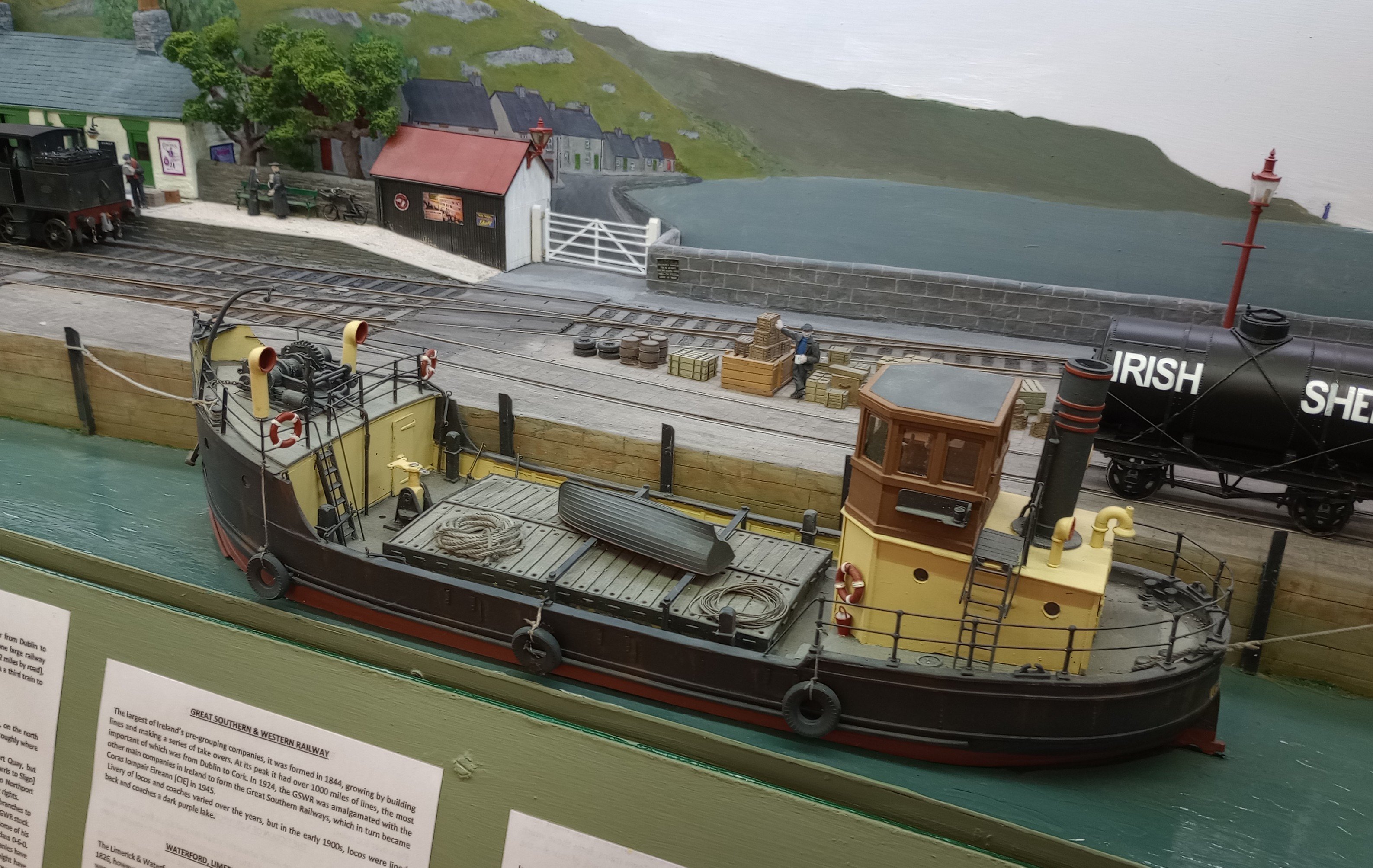
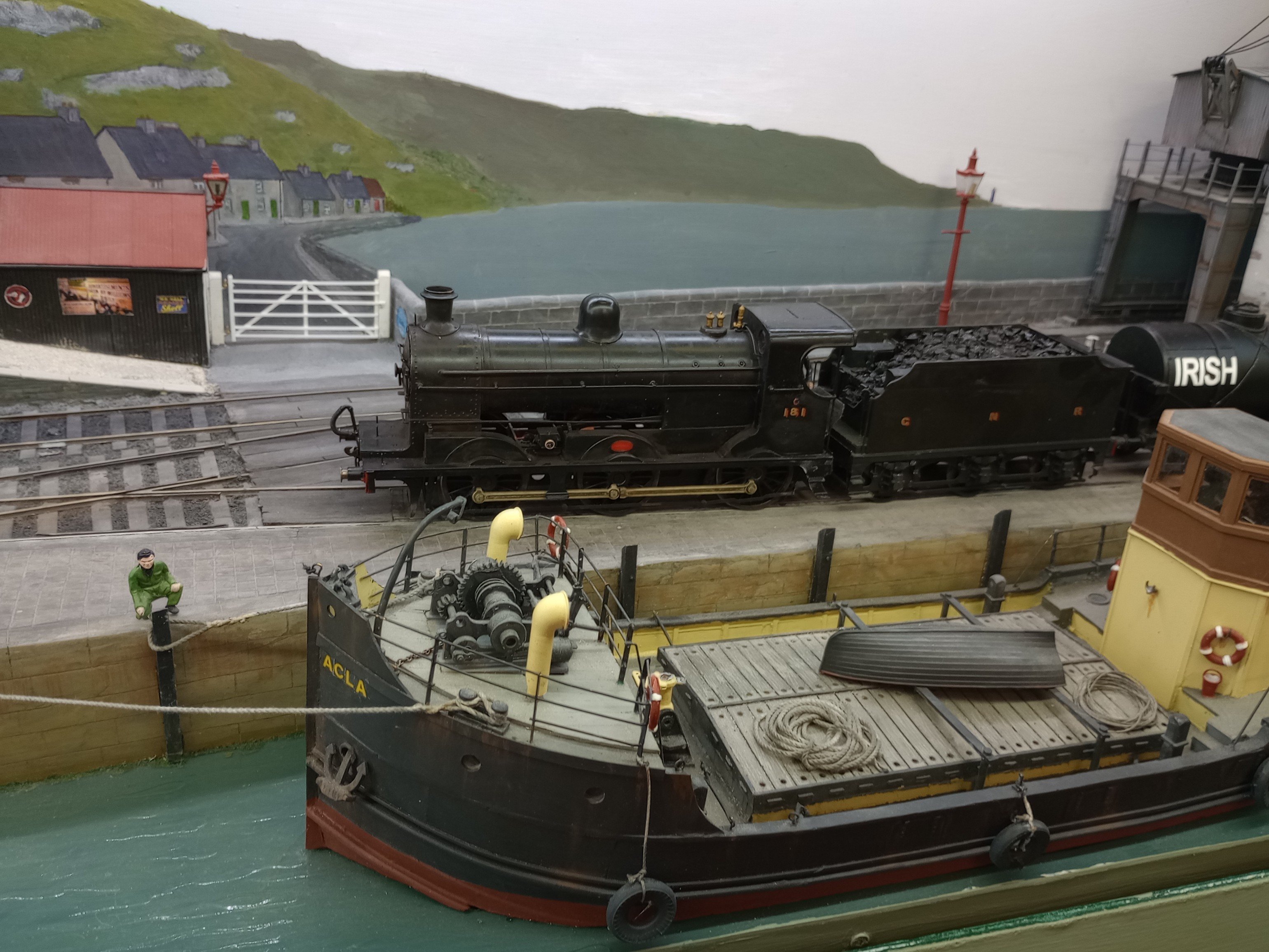
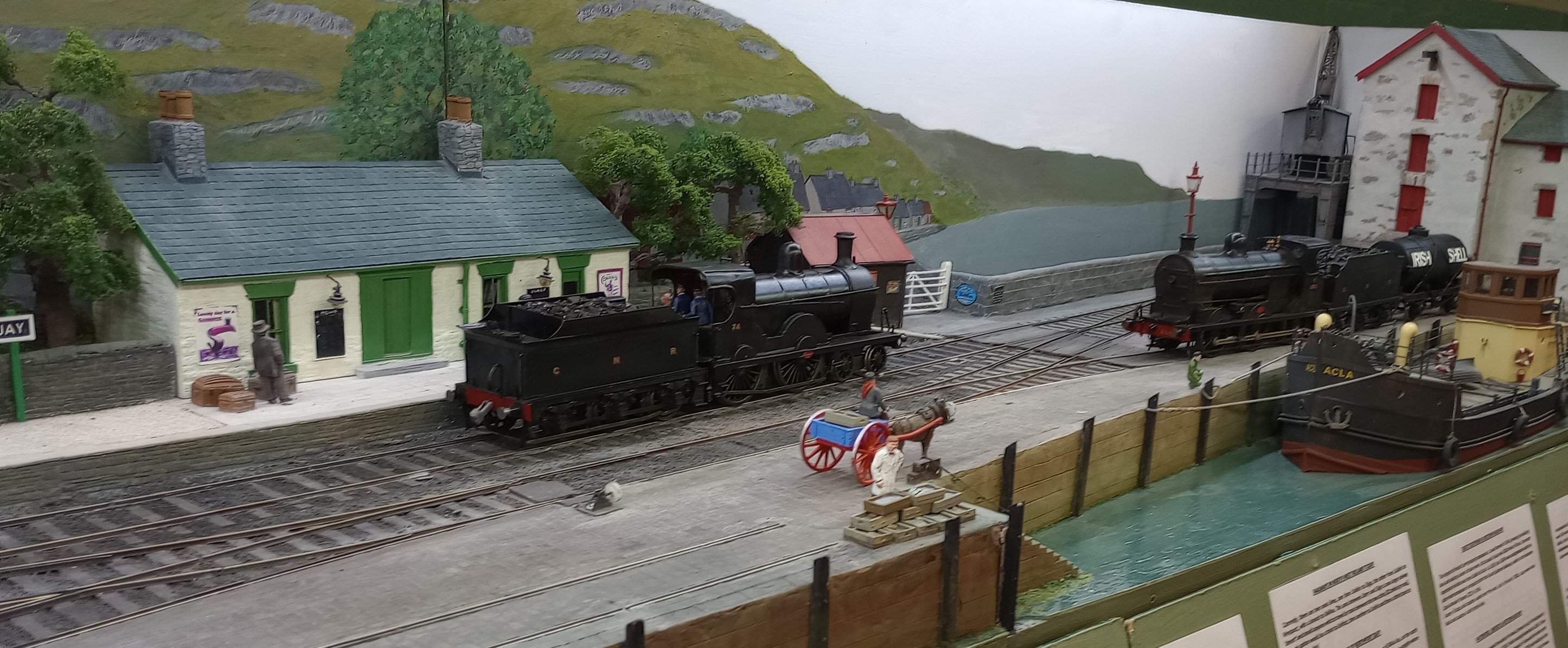
Sunday proved to be interesting in lots of ways. First thing, a chap arrived and asked if he could film the layout. Never a problem, but wasn't expecting him to stay for two hours! Things were a bit sticky to begin with but hopefully when edited may prove interesting, so look out for Celtic Film on YouTube and please post if you see it before me. One of the other layouts at the show was Cadhay Sidings. P4, but many of the crew had been part of Richard Chown's Castle Rackrent, so during the day I had regular requests to display his WLW Shannon. Good job I didn't take it home on Saturday. Below are a couple more pictures of David's GN stock, plus view of my coaster, Acla. The main mast collapsed when setting up the layout on Saturday morning so the only option was to remove it, along with the crane boom and all the rigging...
- 257 replies
-
- 17
-
-

-
-
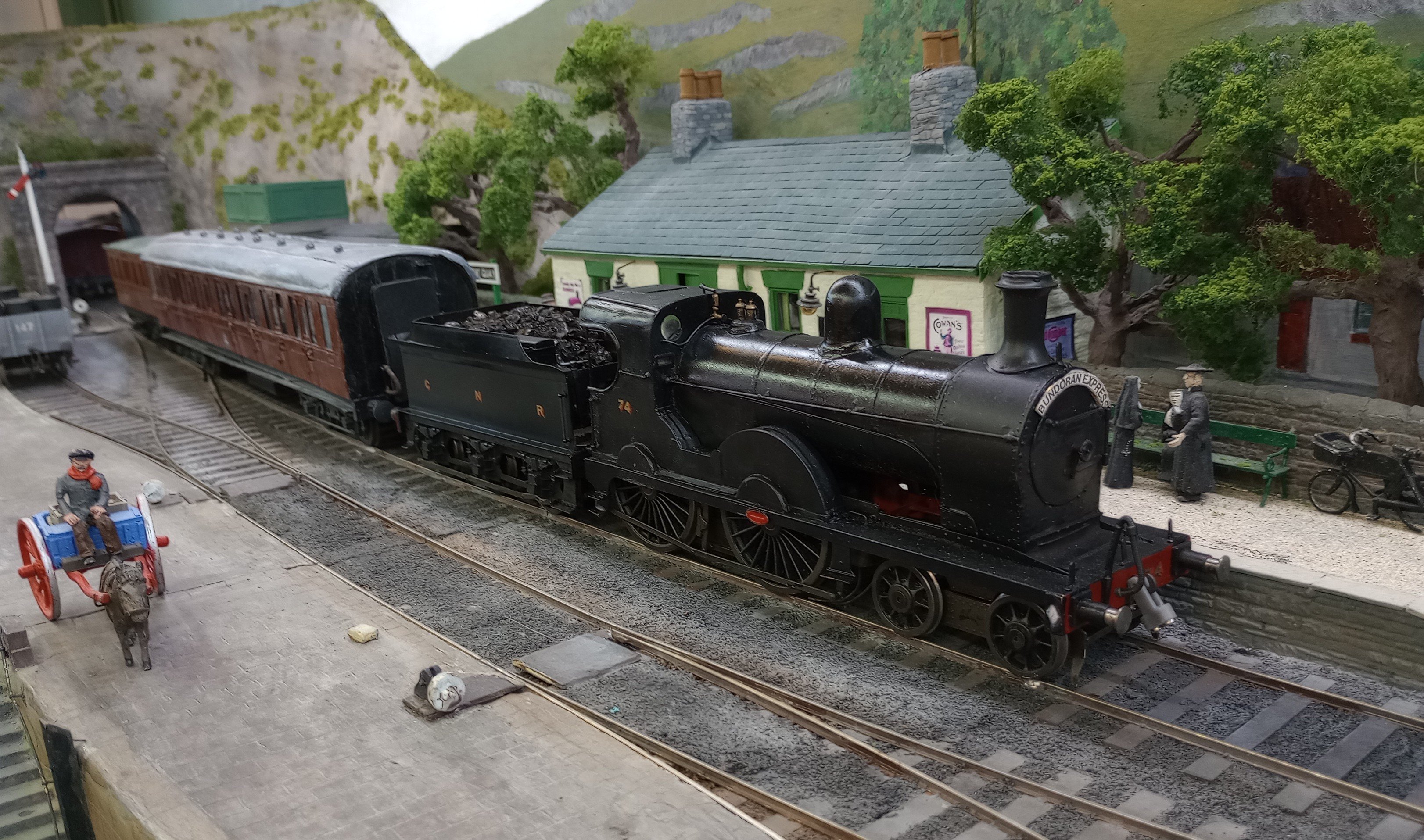
Great to have visiting locos, stock and excellent company today! Definitely a first for a corridor coach and by some margin the longest vehicle on NPQ too. The GN locos are big compared to Sligo stock, but made a great sight, especially with that Bundoran Express headcode! Many thanks!
-
I think your painting and colour palette aligns very much with Martyn's, Alan. However, it is one of those seminal works of reference that is always worth going back to, though several of the Humbrol colours aren't available now. A new version, using modern acrylics would be useful too.
-
Thanks Angus. Full testing begins later next week after NPQ's visit to the Aldershot show this weekend. All my points are 3' radius, so it will be interesting to see how stock performs. Fortunately (?), the Swilly bogie stock only has to stay on the straight bits.
-
Witchcraft and alchemy! Respect....