David Holman
-
Posts
4,359 -
Joined
-
Last visited
-
Days Won
117
Content Type
Profiles
Forums
Events
Gallery
Blogs
Community Map
Everything posted by David Holman
-
The photos of the train by the water are just splendid.
-
Looking great, Alan. Not surprised, your colours have always been subtle and muted. Such things are very much in the eyes of the beholder, but certainly works for me. A range of textures too - really brings things to life.
-
Me too! The photos were taken by CM editor Andrew Burnham at last year's Chatham Show and I gave them the article in the August, so a long wait. However, good for the hobby (and the magazine) that there is plenty of material available. Apart from the obvious buzz of seeing your efforts in print, you get paid too and am thinking there are quite a few layouts and models of this parish that could send in something. All you have to do is check the editorial page, though they do like large file pictures, for obvious reasons. Andrew uses a 24mp camera and natural light on long exposures, but with digital camera it is easy to experiment. They like prototype stuff too and with the recent growth in the range of Irish models, articles on Irish practice, new and old could be useful. Now there's a thought...The NPQ will be at the Aldershot show in October (the one I missed last year) and some GN stock will be visiting too.
-
Northport Quay will be in next month Railway Modeller.
- 167 replies
-
- 10
-

-

-

-
In 7mm scale you get whitemetal castings for the stools and wire for the rodding = much more robust. One wonders what they do (if anything) in 2mm scale. Tame spiders maybe? Am sure you'll enjoy the static grass machine, though the puffer bottles are still useful for small areas and tight corners. A good tip is to put down a layer of scatter crumb first and then static over the top of that. Never use a single colour either. A blend of several works best and experimenting is very addictive!
-
Got a lot of the necessary evils out of the way there, Alan and to very good effect as well. Love the rattle cans idea, and while really must try to embrace my air brush more, it is such a faff. Static grass machines much more fun.
-
Y.A.R.D. (Yet Another Repeat Distraction) 1: Coolnamona
David Holman replied to LNERW1's topic in Irish Model Layouts
See what you mean. Despite the very large buildings, there seems considerable potential for a working diorama, with the track plan looking quite simple. Anyone got a map of the area? -
That looks very good. Any chance of a more detailed breakdown of construction? For example, what are the blocks that the rollers are mounted in? Daft enough as I am, to model in three gauges (21, 32 and 36.76mm), looks like there is potential to create a multi gauge rolling road using your method.
-
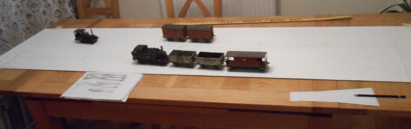
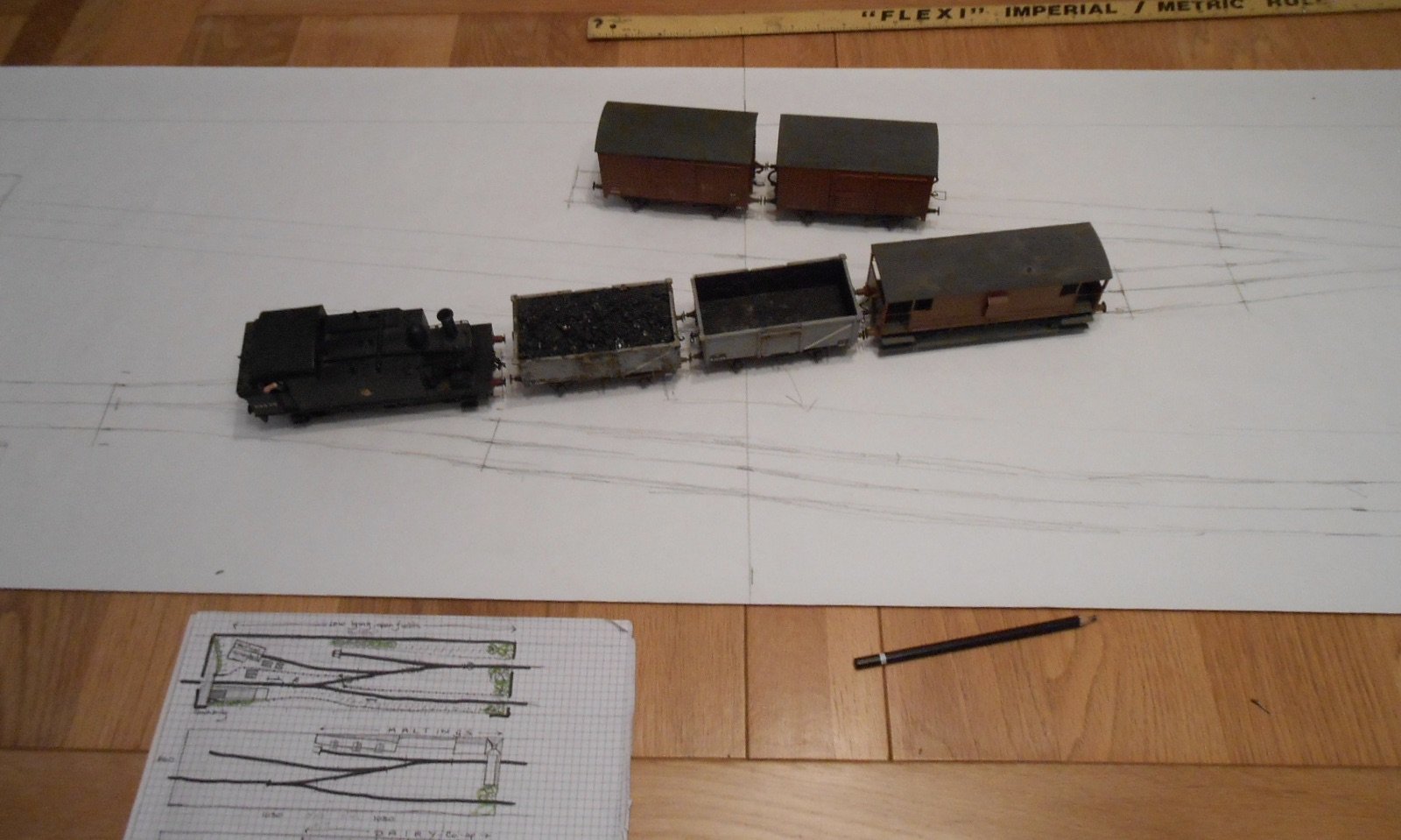
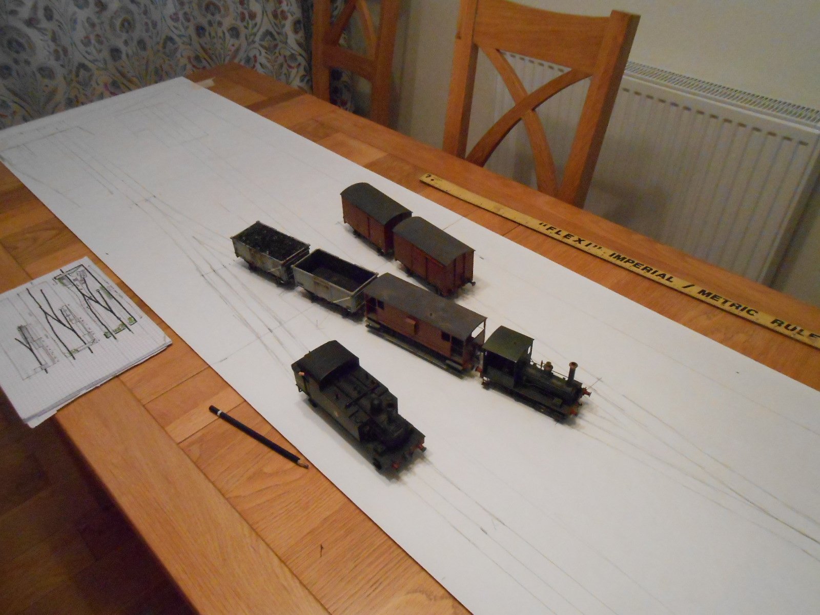
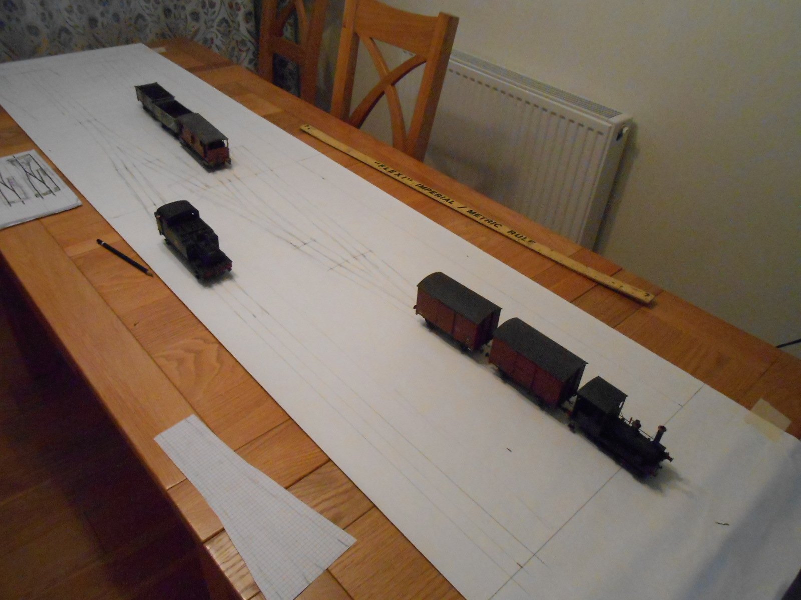
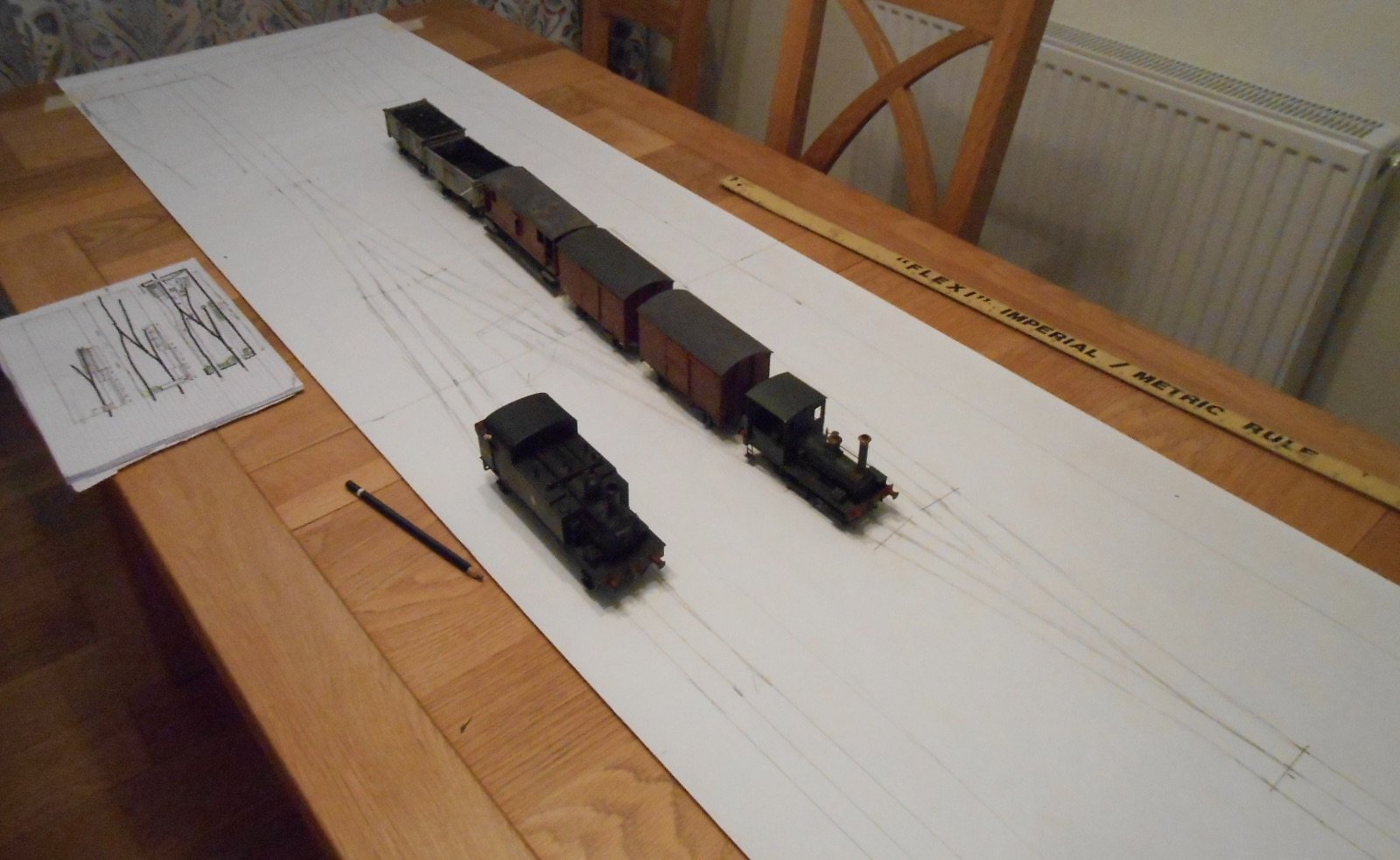
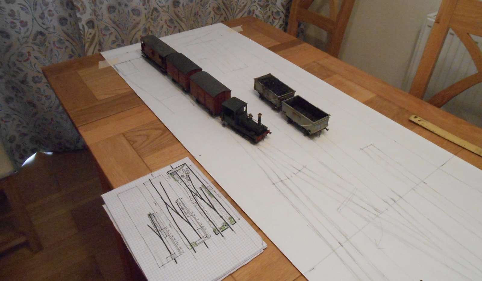
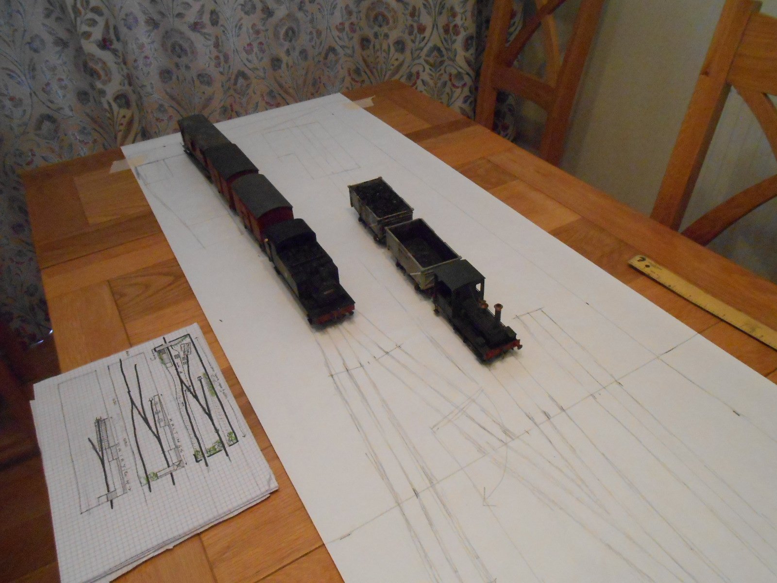
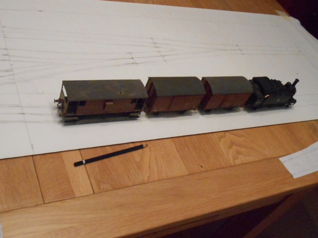
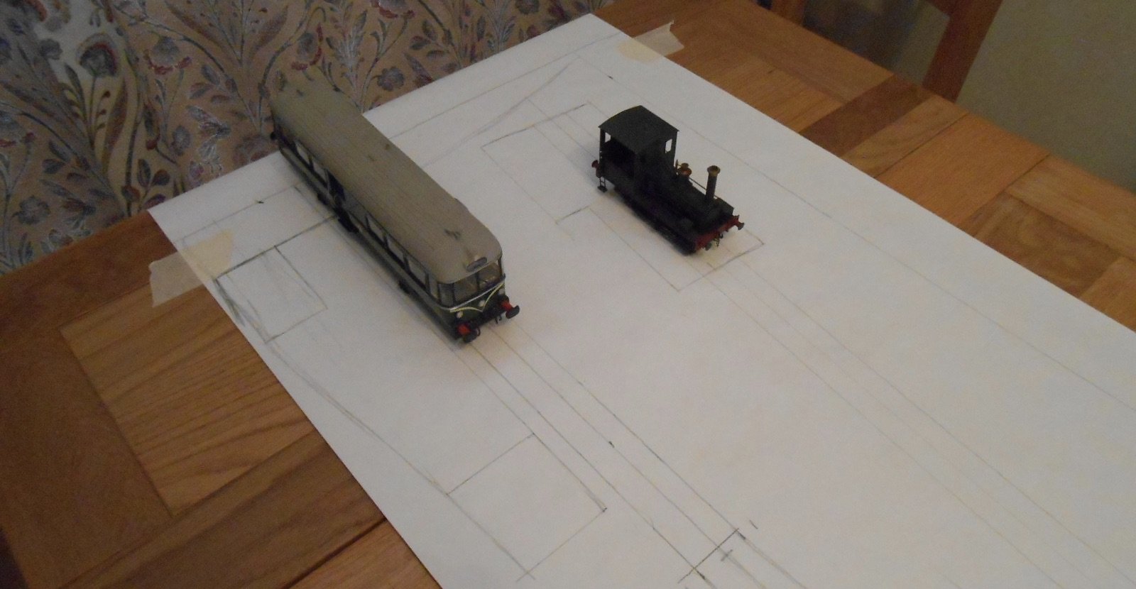
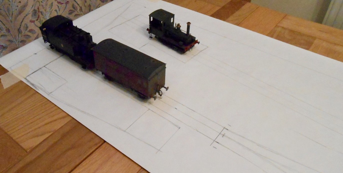
Building upon my zen [!] this afternoon, spent a pleasant hour or so drawing out the new project full size on some lining paper. Doing this helps ensure that the clearances are adequate, especially as you can pose various items of stock. I also moved stock around to check that likely sequences would work. Unfortunately, it is hard to see the pencil lines of the track plan, but my sketch plans should help with orientation. The first picture shows my J69 approaching the junction to the private sidings with a typically short goods train. Behind, ex Wantage Tank, Jane waits in the loco shed road, while the two vans are in the rear siding. The next two pictures show how the J69 can push its train into the private sidings [note the mainline engine would not be allowed through the gate], for Jane to collect. Jane then moves the train into the loco shed/exchange siding and then collects the two vans from the rear siding, placing them with the brake van. The two vans and brake now form an out going train, which Jane moves on to the mainline, for the J69 to collect. After, Jane will shunt the open wagons off scene for loading/unloading. The final two pictures show my railbus in the platform of the halt and the J69 in the same place with a horse box - again, both typical workings from 1950s East Anglia. So, it all seems to work, which is just as well as I've already put in an order for some 6mm pre-cut birch ply. At the moment, it may well be all the track will be bullhead [Peco], but using Marcway 1.8m wye points because they are such good space savers. Other orders will go in soon: three tortoise point motors, four uncoupling magnets, plus associated switches and wire.

-
Self adhesive address labels do the same thing, though require patience to cut out, leaving the glazing bars behind.
-
Just watching a recoding of yesterday's Repair Shop (BBC1, it will be in IPlayer). It features the station master's lamp from Donamana on the Donegal line to Derry. The station master was in fact a lady and it is her daughter who has brought it in for repair.
-
Either way, as ever, thank you!
-
Lovely stuff. What is the large warehouse structure behind Pennyburn shed?
-
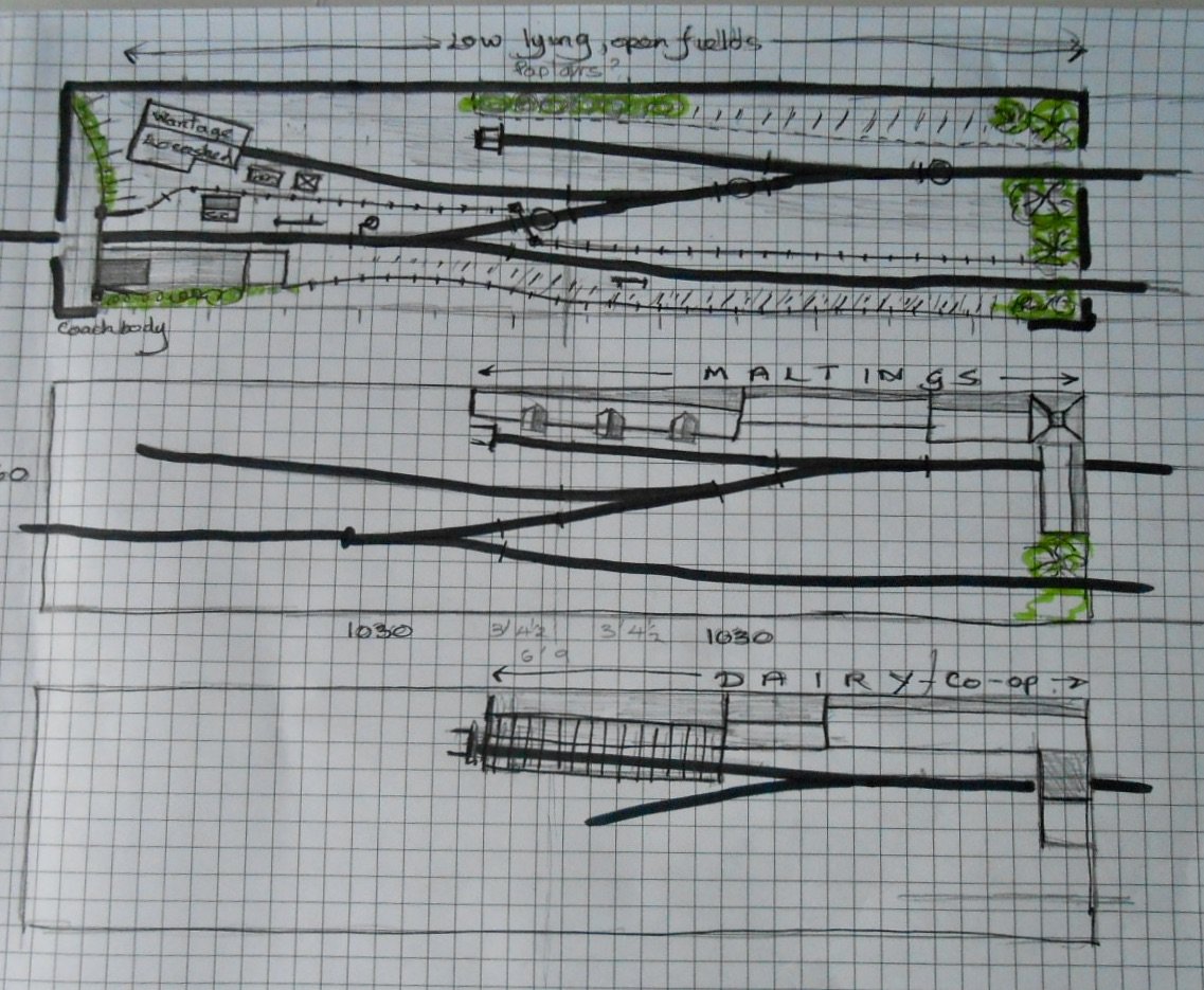
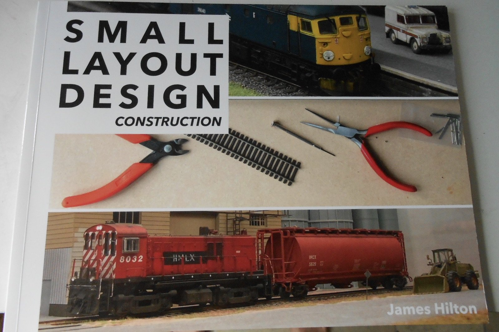
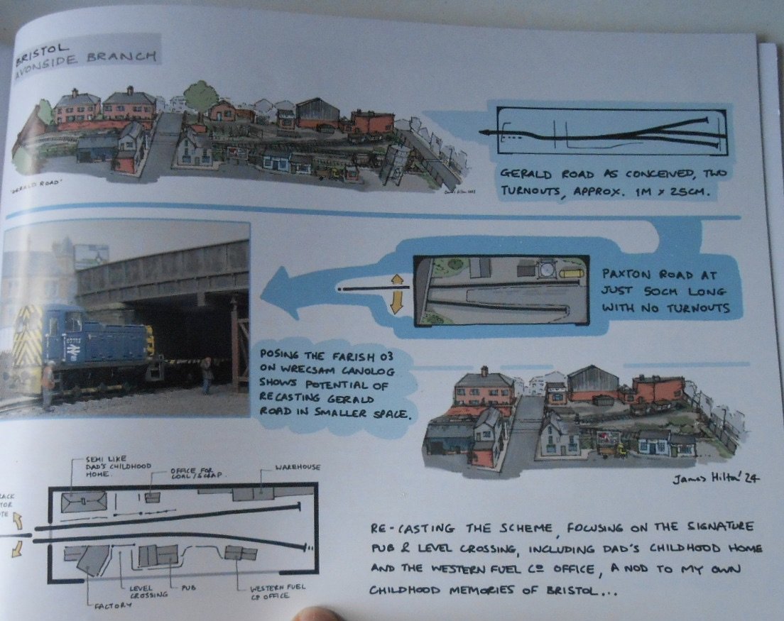
I think you are right about that extra point, while have also tinkered around with the position of the others, as shown below. The other two sketch plans give an idea about other options. The 6'9 overall dimension will be shortened to 6'6/2m, so that I can use the lighting and pelmets from Fintonagh/Swillybegs. No point in making extra work if you don't have to! Moving the point off the mainline means almost all shunting moves will take place on scene, while making the loco shed siding longer means it can double up as an exchange siding. The initial project will see the narrow area against the back scene as just a low bank, with a row of poplars to hide the baseboard joint. A couple of trees on the right should hide the exit from the fiddle yard, while the back scene itself will be painted to represent low lying countryside. Shades of Wissington, perhaps. Both these sections will be removable, to allow a granary/maltings low relief set of buildings instead and [later still] a dairy cum Co-op option. I've worked out what I need for the baseboards and an order will go in for some pre-cut 6mm birch ply. Track on the mainline will probably use either Peco or C&L flexitrack, with one of the latter's point kits, so everything will be bullhead. The private sidings will be Code 100fb on copper clad sleepers to give a lightweight look . With only a few buildings and scenic items, there is every reason to get as much fine detail as possible. Am thinking the locoshed at Wantage Town, while the passenger halt may just do with a grounded coach and/or van body. As well as recent projects on this forum, inspiration is also comimg from some new books by James Hilton & Wild Swan. They very much focus on minimum space/maximum detail and are well worth getting hold of.
-
Note to self: next time I build a new engine, really, really must visit this thread beforehand. Practical and inspirational.
-
Don't see a Bentley there, but the photos very much evoke what Patrick Whitehouse captured!
-
Very much shows how important it is to weather and detail track. Subtle touches, but brings it all to life.
-
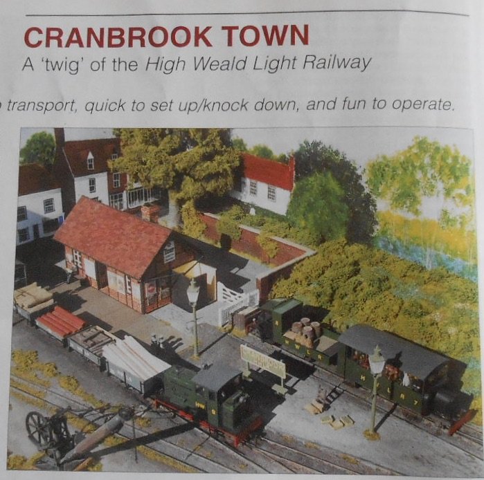
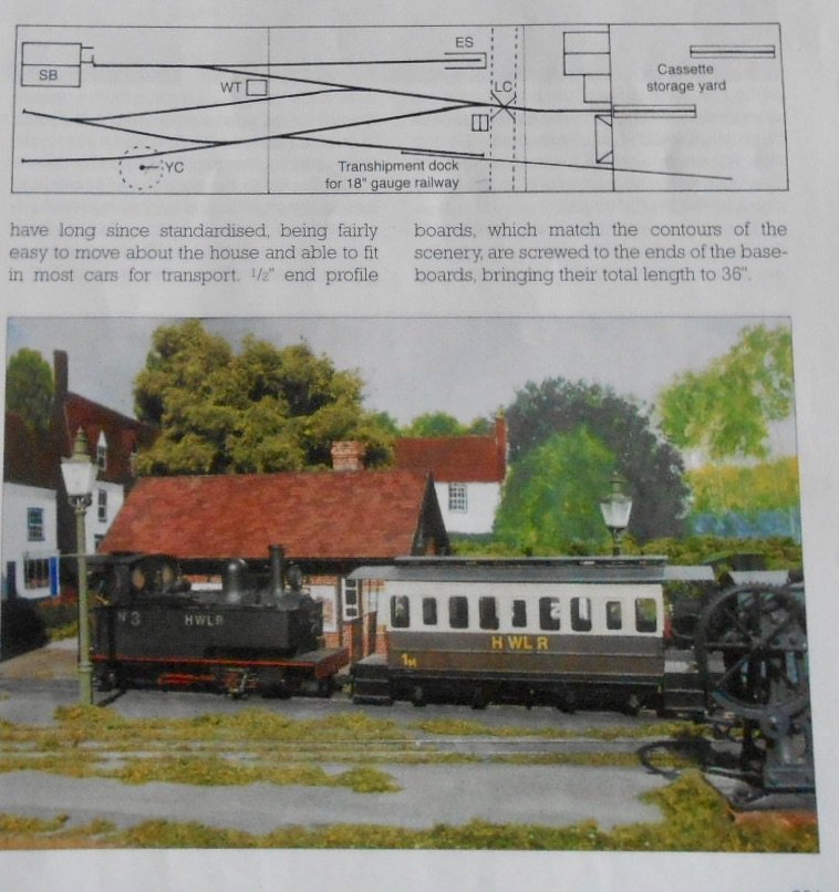
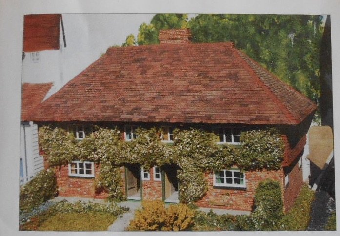
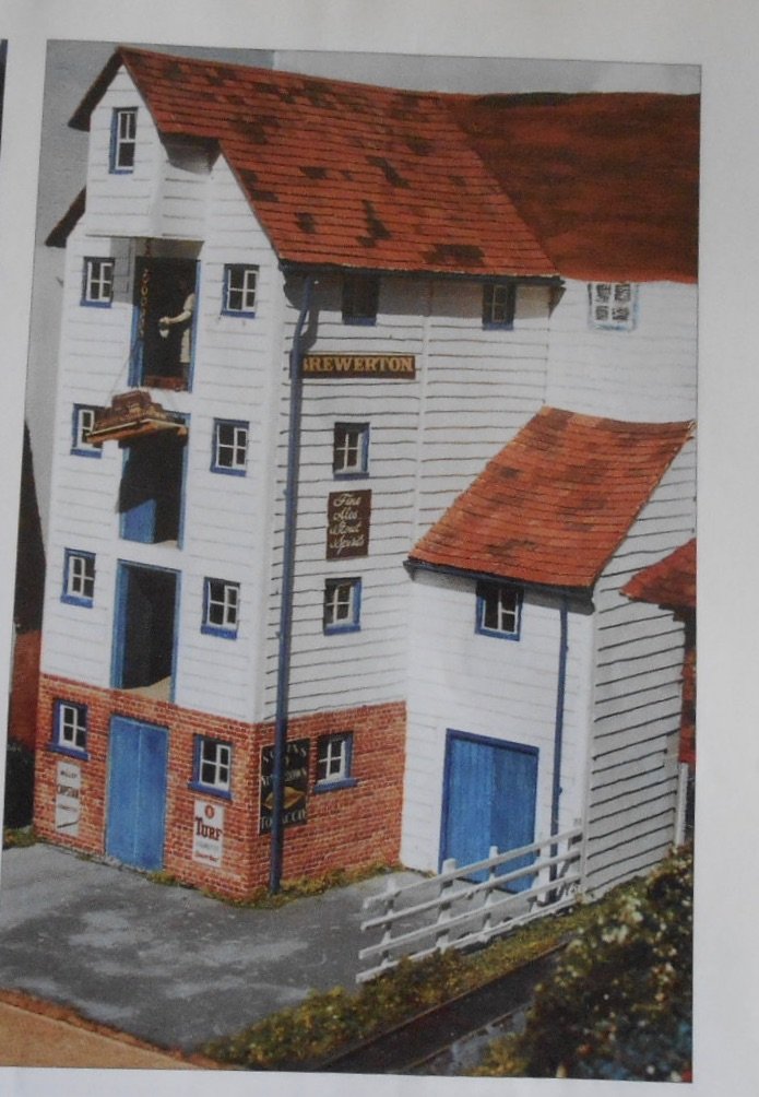
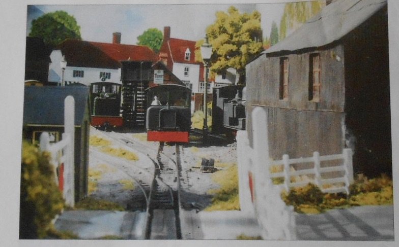
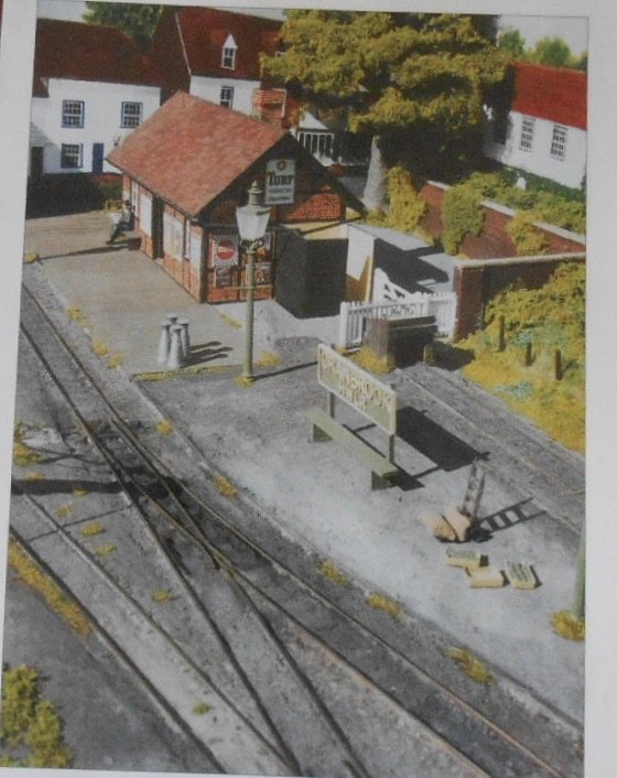
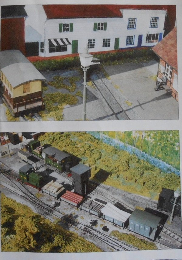
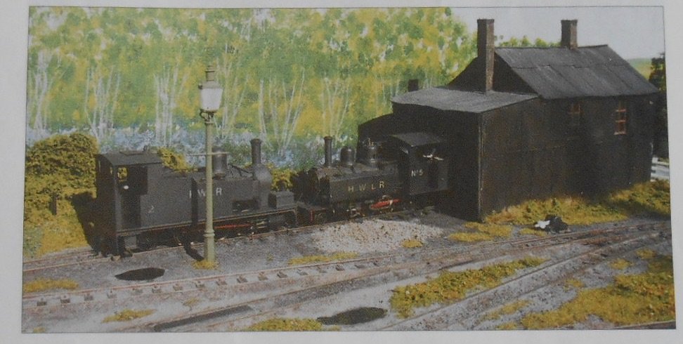
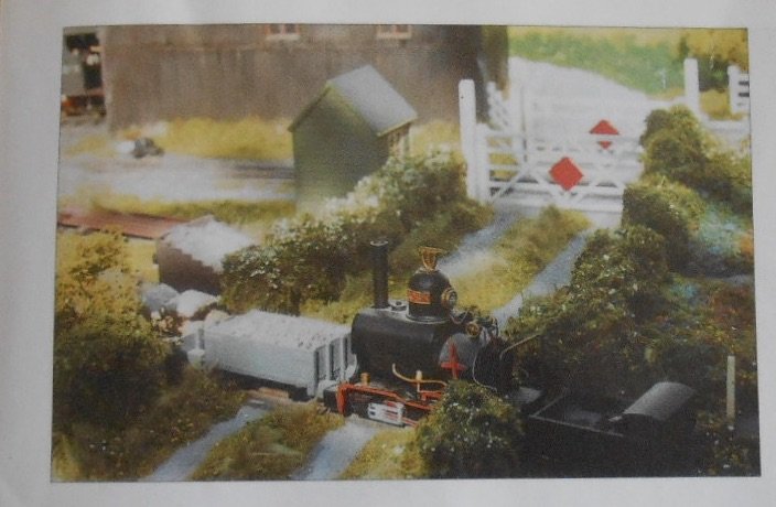
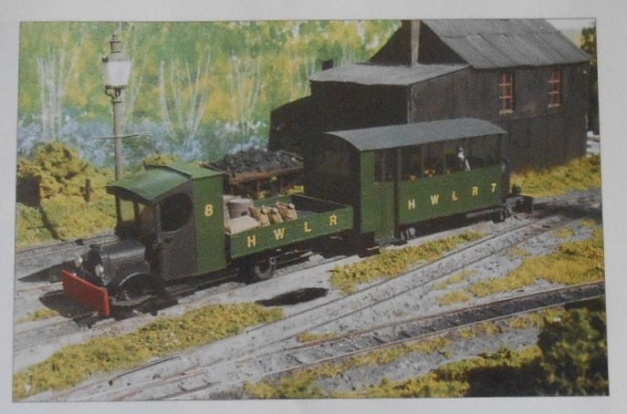
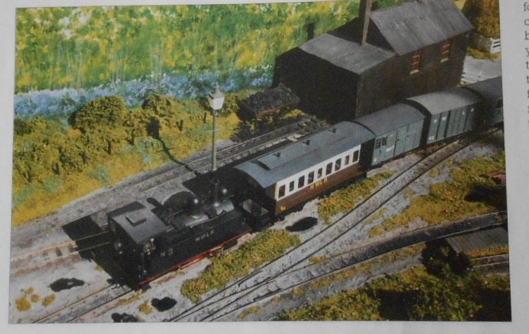
Cranbrook Town My second 0n16.5 layout, Cranbrook Town was built after Loose End and before Eatonswell, appearing in the April 2003 RM. It was very much another part of the High Weald fiction - a twig off the branch to Hawkhurst. When the latter went in the council crusher, I'd kept all the buildings, so this new project was seen as a 'quickie'. Hence everything was kept as simple as possible: three baseboards [3' x 2'], two feet of which was the fiddle yard on the third board. Track was Peco 0n16.5 and I noted in the RM article that it took just a weekend to make the baseboards and another to lay the track. Nice. I'd kept all the Hawkhurst stock, so a short piece of 9mm track was laid too, while the fiddle yard used cassettes again. Scenically, the idea was to use the integral back scene to extend the overall picture, trying to show things such as a town scene, but also a bluebell wood and farmland - all very Kentish. Buildings included a Wealden Hall House and a large mill. A few new items of stock were added and as I was still freelancing to some extent, one involved the chopping up of the then newly released Bachmann 08 shunter. The body was rearranged on a new, wider, footplate, together with a new cab. The chassis, with its outside cranks, was a superb runner, making it ideal for shunting with the pick up goods, as shown above. Another new model was the Baldwin 4-6-0T. A Wrightlines kit and therefore mainly white metal, it was one of those that didn't actually go together very well, but once finished, seemed to hang together quite nicely, while the weight made it a decent runner. A real talking point, proved to be my railbus/lorry combination. The Selsey tramway had one of these for a while. The passenger half of mine was one of the old MTK 'El Crappo' [yes really] etches, while the lorry started life as a Corgi Lipton's tea van. I removed the body and replaced it with a dropsided flatbed. I also made up one of the [even then quite old] Branchlines kits of a Clogher Valley coach, which [though I didn't realise it at the time] started my moving towards the Irish scene ten years later. There was another purpose to the layout, because in a mercenary sort of way, I always intended to eventually sell it, with all the stock, as a going concern. And so it proved. After a few shows, I started advertising it at exhibitions & it wasn't long before somebody made me an offer and it went home with him instead of me. I believe it is still with the new owner, getting good use, which is very pleasing. So, there we are, a trip through my 0 gauge modelling, which which hopefully now gets a revival with a new minimum space layout. Planning is making progress, so I should have something to report on this soon.
-
The yard surface is just sublime - had to look twice before I realised it was photos of a new model. Have you ever tried the trick of filing a flat on the tyres of a road vehicle? May not show up in 4mm scale, but it 7mm it gives a subtle touch to make the model 'sit' with tyres looking like they have real weight pressing down on them.
-
The saving grace of outside valve gear on a model is that while it looks complicated, most of it doesn't do much, other than rock to an fro a bit. Outside cylinders, with their piston and conrods, do a fair bit more. Add in brake and sanding gear and it all starts to look a bit scary, with lots of opportunities for electrical shorts - which I'm sure our man is well aware of!
-
Great work, but which brought back painful memories of my own attempts at such alchemy!
-
Good stuff & very interesting.
-
Lokks like se the same problem is happening again, as per original post on this thread. Site doesn't seem able to upload photos. Text ok though. Message reads Error Code DSCN 6832 jpeg could not be saved.
-
Nice. Very nice indeed.
-
You can't see it in the photos, but the greengrocer was Edward King. Several excruciating puns in the headlines at the newsagents too.