David Holman
-
Posts
4,359 -
Joined
-
Last visited
-
Days Won
117
Content Type
Profiles
Forums
Events
Gallery
Blogs
Everything posted by David Holman
-
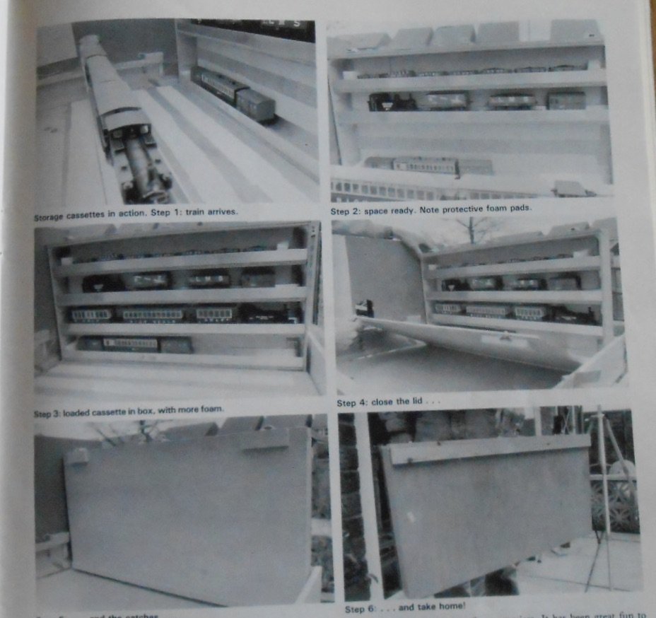
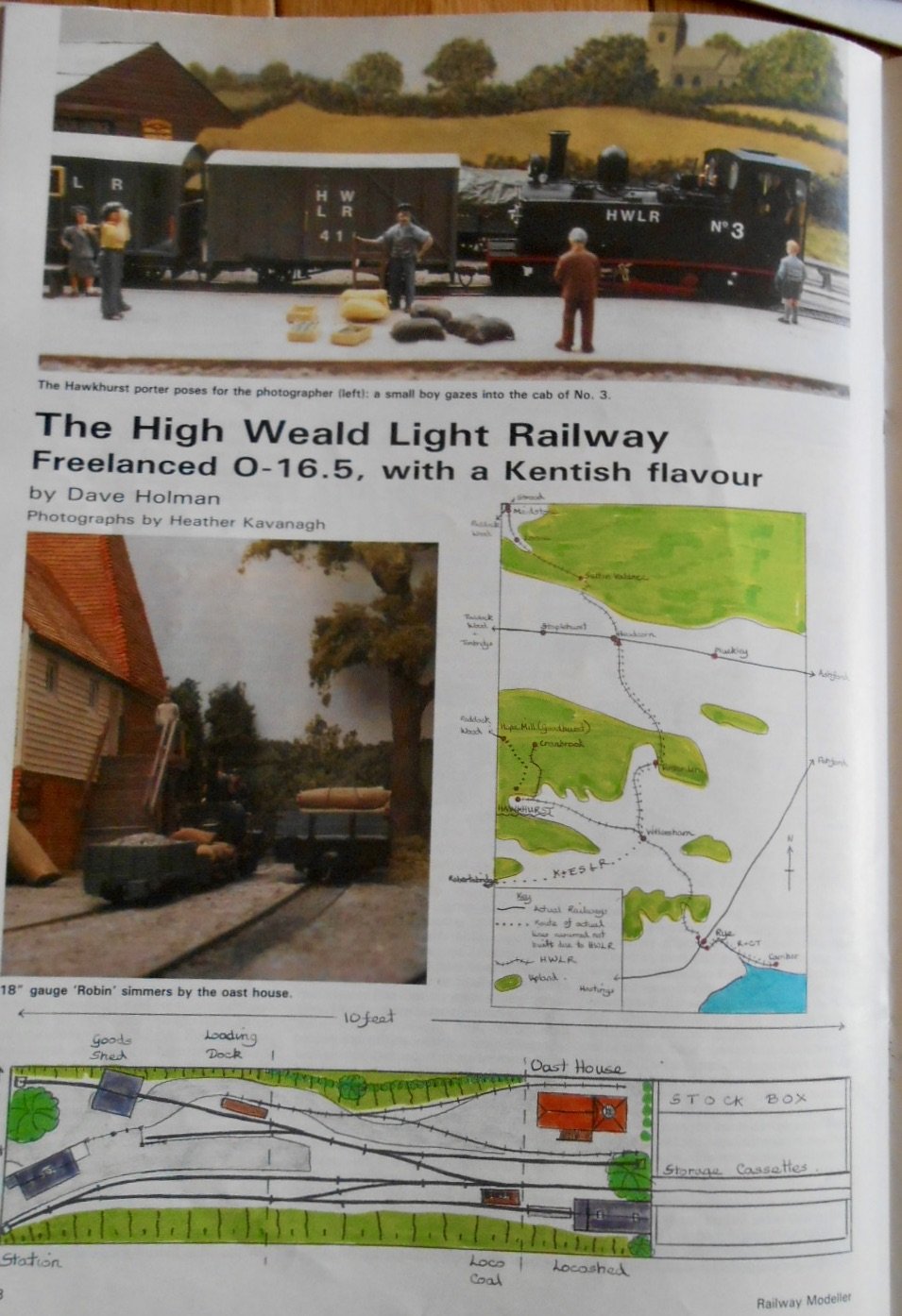
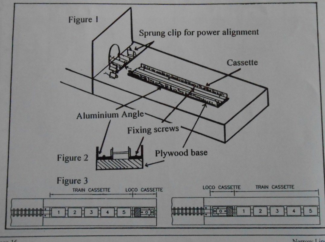
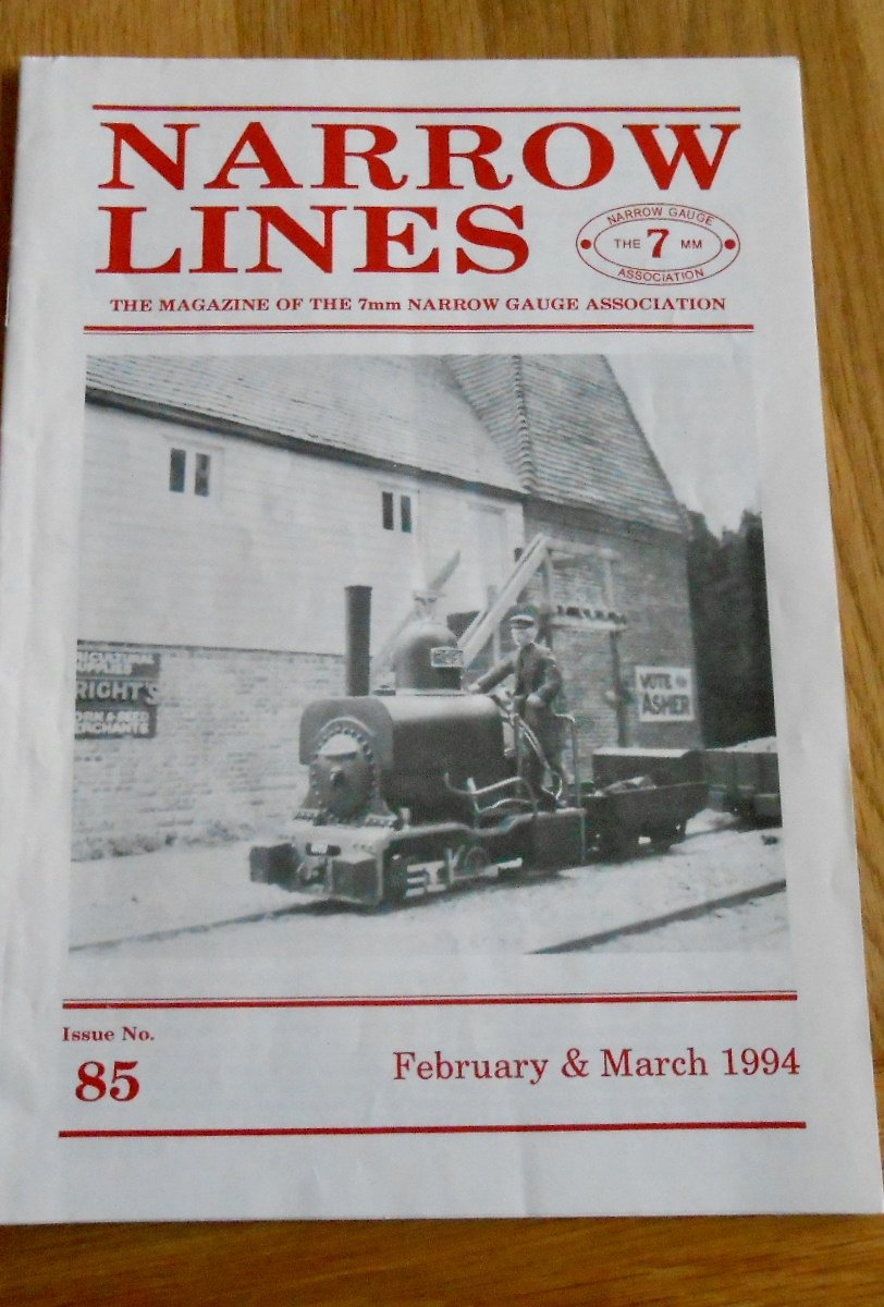
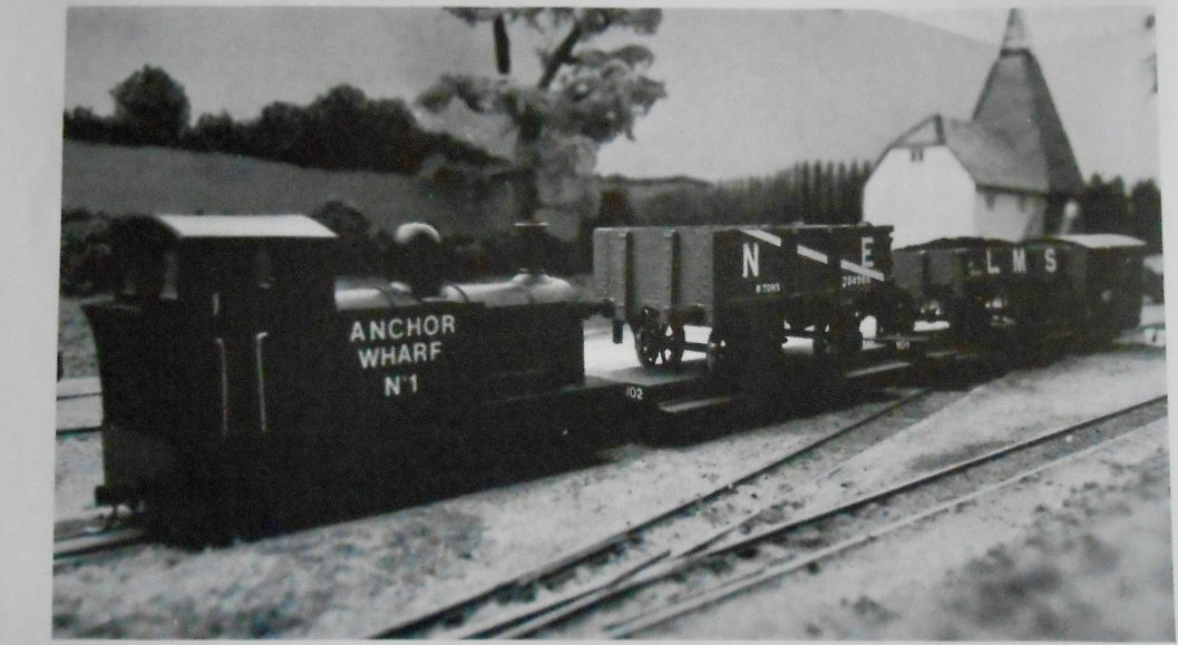
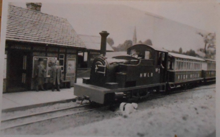
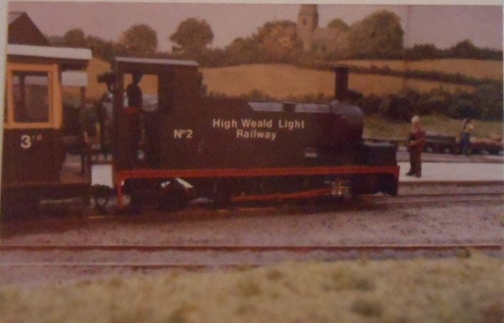
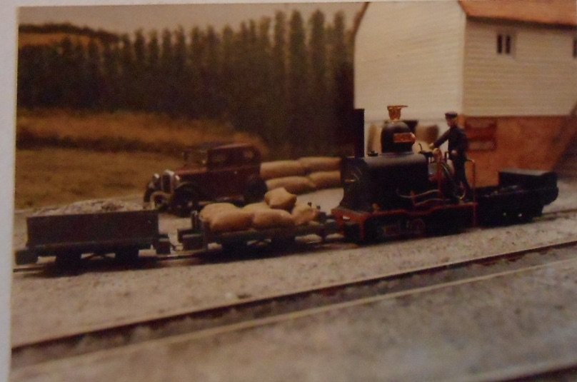
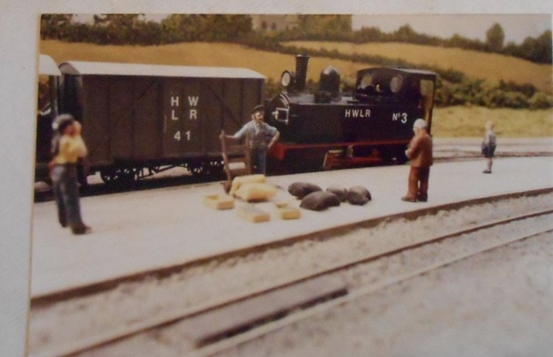
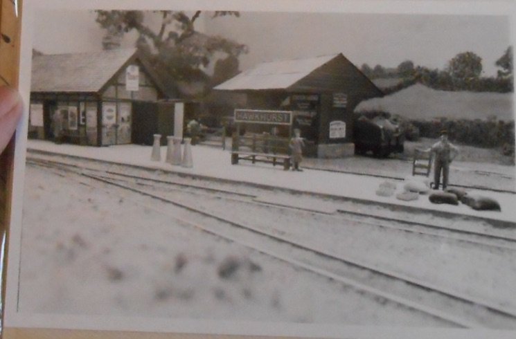
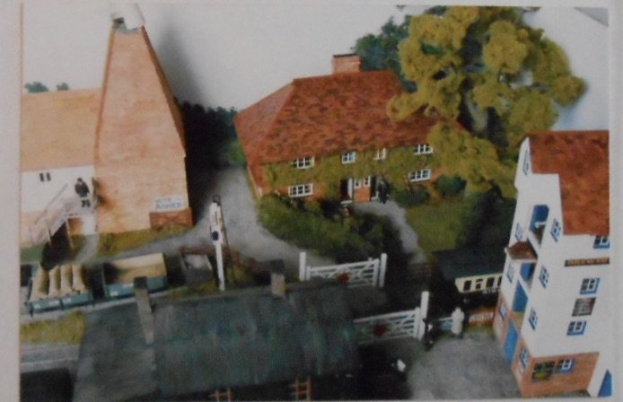
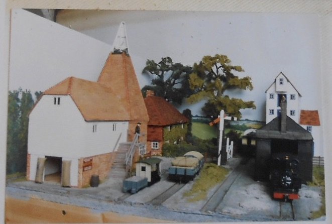
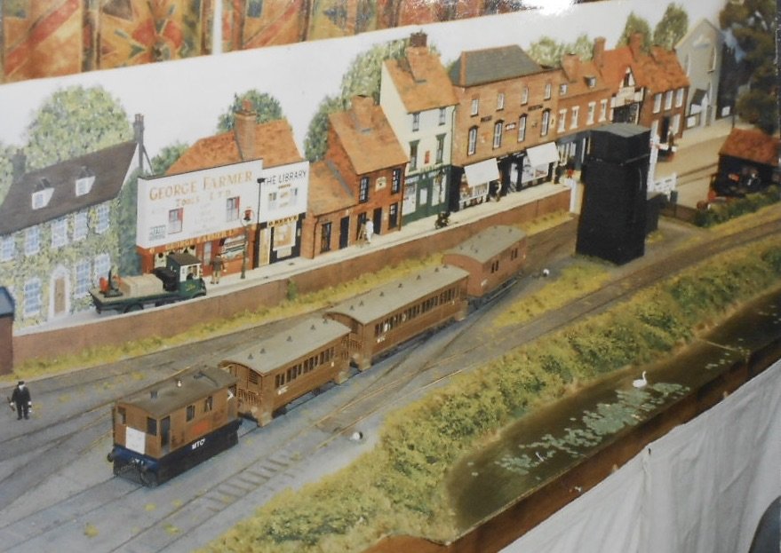
Already on my third or fourth version and not convinced I've got the design right yet! Drawing it out full size on lining paper should help, so I can pose stock and add some basic cardboard mockups of buildings too. However, before any more on the new project, thought I'd finish off my early 7mm scale stuff by going right back to the beginning and 0n16.5. This was in the late 1980s, so not only are the pictures photos of photos, some are actually in black and white. The layout was called Hawkhurst, High Weald and it appeared in the Railway Modeeller in 1991 and Narrow Lines [7mmNG Society Magazine] in 1994. The pictures below show the track plan and map of the concept. The latter very much a Colonel Stephens theme, being a narrow gauge line running across the Weald of Kent from Rye to Maidstone, replacing the Kent & East Sussex; with a branch to Hawkhurst for good measure. Construction was very 'old school', with chipboard on 3" x 1" softwood frames, though the fiddle yard used a newish idea of cassettes. Trackwork was hand made, using Code 100 fb rail on copper clad sleepers, the first time I had attempted this & not that successful if I'm honest, though the points gradually got fettled into something workable. There was also a small amount of 9mm gauge track, as I had bought the 0n9 kit of one of the Horwich Works 15" gauge shunters. Stock was very freelance, mainly scratch built plastic bodies on 00 chassis. Plastic water pipe worked for loco boilers, while chimneys were often 00 ones cut in half and then made longer with some brass tube. All very home spun, but being freelance I didn't need to worry too much about accuracy. The Lima 08 shunter was useful, with its outside cranks, while a GWR 2-6-2T was made into an 0-6-2T, with the front pony going to the 08 to make a 2-6-0T. Another loco disguised its old Hornby 0-6-0 chassis by having full side skirts. It is seen with a couple of transporter wagons [my first standard gauge models], as per the Leek & Manifold. Pride of the line was a Vulcan kit of the Hunslet ex Sierra Leone 2-6-2T. My first 'proper' 7mm scale engine, it was quite a leap of faith with its RG4 motor and outside valve gear - the latter seriously scary stuff, being held together with 14ba nuts and bolts. Probably beginners luck, it actually ran really well. Wagons and coaches were mainly built on 4mm Ratio under frames with plasticard bodies. The buildings were all based on typical Kentish types, including a Wealden Hall House and the classic oast. Really went to town on these, using the same methods I later used on Loose End. The station building was based on an Arthur Paine design like the one at Hemyock. After debuting at the Chatham Show, the layout did several other ones, including Expo Narrow Gauge, possibly the last one held in Greenwich Library, before the show moved to Swanley. However I found that the chipboard started to sag, thanks to inadequate bracing, so after a couple of years, I carefully removed the buildings and the rest [including the track], went to the council recycling centre. I then turned my attention to standard gauge, with Loose End, though narrow gauge later featured in similar layout called Cranbrook Town, of which more next time. Hawkhurst taught me a lot, particular in terms of basic scratch building. I enjoyed freelancing too - trying to be faithful to general railway practice, without needing to worry too much about overall accuracy, while working in 7mm scale [albeit in narrow gauge] showed me certainly got me hooked on larger models.

-
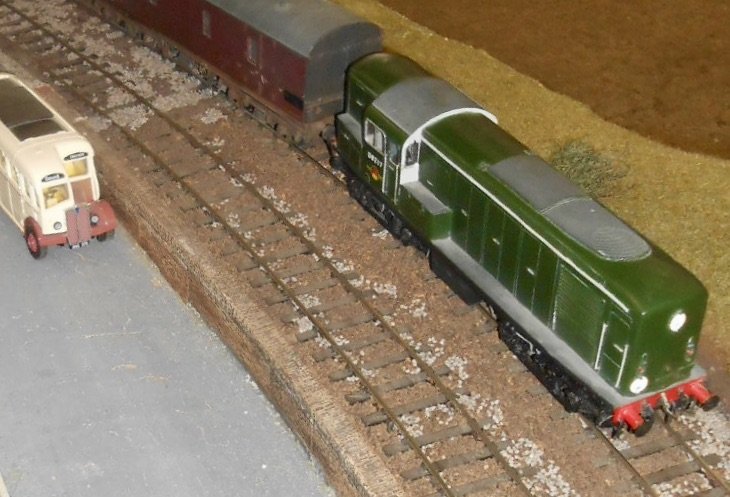
Headlight, lots of hoses. Driving end of a railcar/dmu. Or inspection saloon maybe?
-
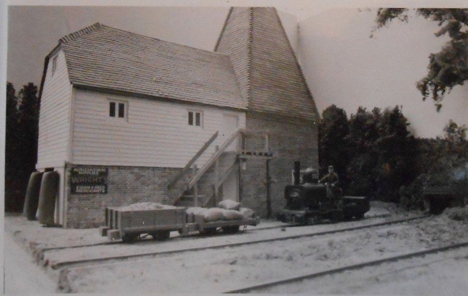
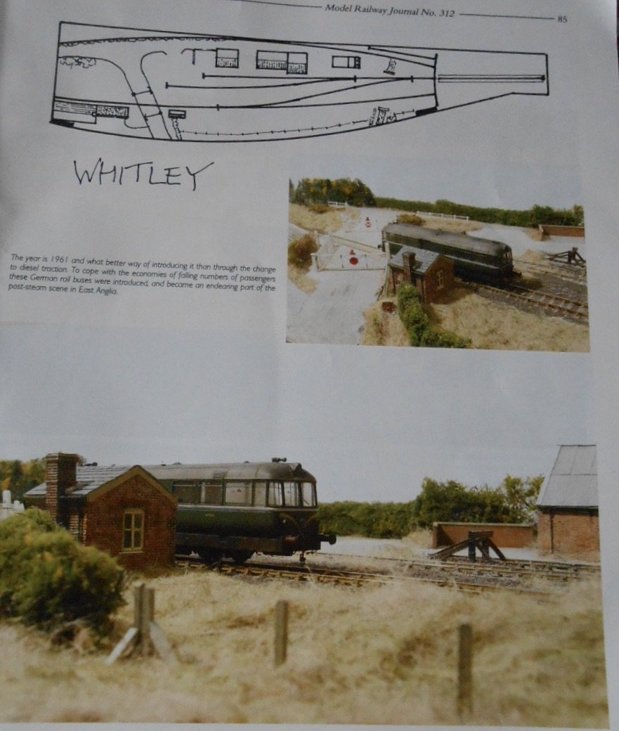
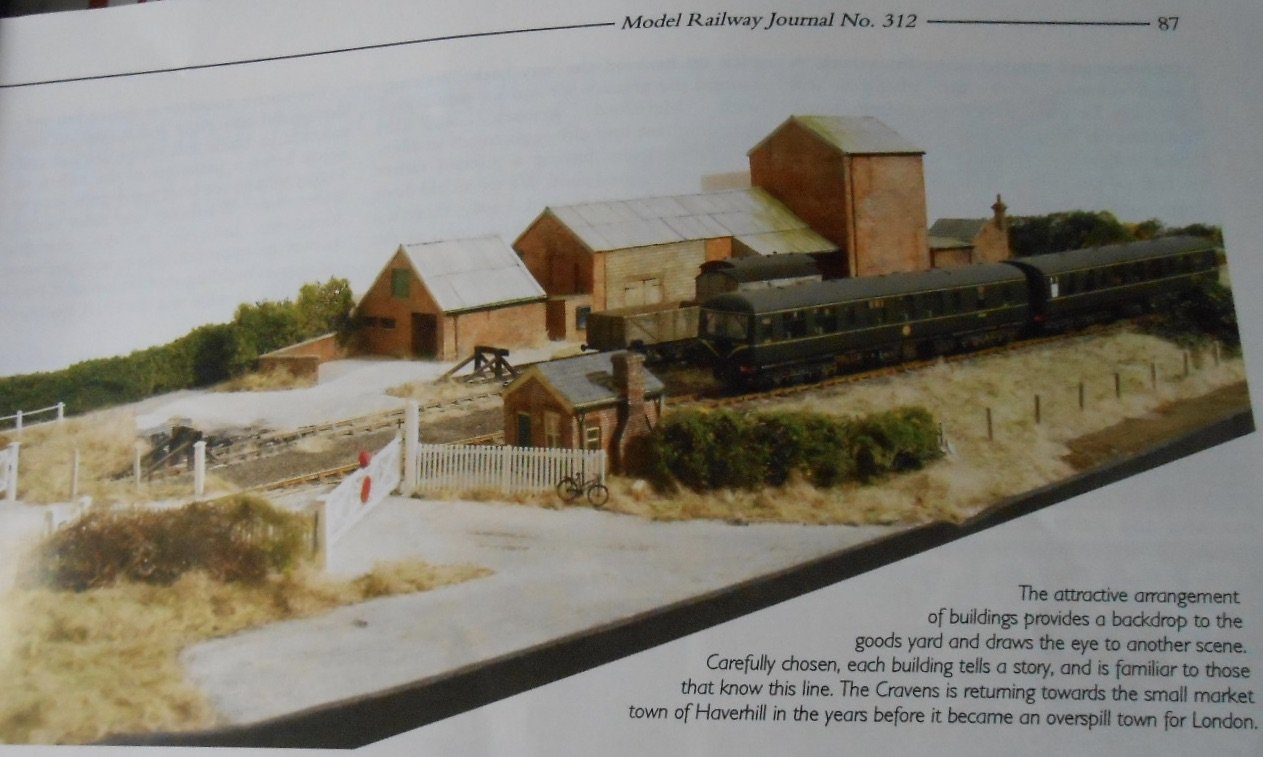
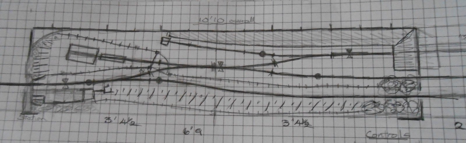
So, time to come clean about my ideas for a new 0 gauge project... As I've said earlier, it all comes down to rediscovering all my stock that has been languishing in boxes for the last ten years or more; that and a fascinating article in the latest Model Railway Journal called "A tale of Three Stations or more..." As you can see, it combines Iain Rice style design, with one of his favourite subjects, an East Anglian byway. Very much a 'part layout' [with a fiddle yard taking the place of half the loop], it appealed to my limits of a 6'9" shelf space, expanding to the 11 feet footprint of Northport Quay and Swillybegs' trestles and beams used for exhibitions. It also got me looking back through my books on East Anglian railways - especially those by Dr Ian Allen, John Brodribb and Peter Payne. From these, ideas rapidly coagulated into I scheme I felt could meet my needs: A single track line with a siding leading to a private branch, in particular a small set of exchange sidings The 'main' line could run things like my diesel railbus for passenger traffic, together with short freight trains that could exchange traffic with the private sidings In the 1950s, an East Anglian branch freight could be as little as one or two wagons and a brake van, hauled by anything from a D16 4-4-0, J15/17/69 0-6-0s, F5 2-4-2T through to Class 15/03/08 diesels. The private sidings would be perfect for my ex Wantage 0-4-0WT, or a Manning Wardle 0-6-0T. All of which I have, of course, while among my 40+ wagons are pretty much all the types I might need in terms of vans and opens, plus the essential brake vans. The design I've come up with builds on the MRJ article of '3 stations in one' - indeed I think I've identified at least six. Allow me to explain: The sketch plan shows the single track through line running across the front of the scene. On the right hand side is the main fiddle yard [I'm thinking cassettes at the moment], which will be no more than 30" long, enough for a small loco and three wagons, or a tender engine and two. Don't need anything longer, as the Iain Rice rule of maximum train length being no more than a third of the scenic length demands this. At the other end will be an 18" length of plain track - enough to hold the railbus before its return journey, or indeed a loco with a parcels van or two. There were a lot of light engine movements or loco and brake van in East Anglia at this time. The main line will be Peco bullhead track, but the private sidings will be flat bottomed, Code 100 rail on copper clad sleepers to help emphasise a lightweight look. All four points will be Ys: in particular the Y points offered by Marcway of Sheffield. Have used these many times, because they are such space savers. A 6' radius Marcway Y is just 12" long, compared to 18" for the Peco one. As you can see, there is half a run round loop [the right hand fiddle yard does the other half], plus a siding with a small loco shed and a kickback siding. The key to the multiple personalities lies in the shaded area in front of the back scene. This will hold a range of exchangeable 'jigsaw' pieces [another Rice idea] that will mean I can change the personality and purpose of the layout over time. Initially, this will probably be just a section of low cutting, with open scenery behind - very Fenland, in fact. A couple of trees should hide the exit to the fiddle yard. In this form, the private branch could have at least three forms: an agricultural line, such as the Wisbech and Upwell Tramway or the Benwick branch An army depot An airfield branch - both of which were common in the area and offer a wide range of traffic However, if this scenic area is replaced by buildings, then there a several ideal prototypes which could be used: Maltings and granary - am thinking Snape in particular, which had its own BR operated branch, but there were plenty of others with nice buildings such as Hadleigh, Saffron Walden or North Elmham for inspiration. I particularly like the archway at Snape, where in reality, wagons were shunted by horse or road tractor. In my case, it makes a nice scenic break which I can use in the other concepts below. A jam factory. Yes, really - the Wilkins factory [still open today] on the Kelvedon and Tollesbury Light Railway was rail served, albeit by the branch goods, but there were enough sidings on the site to merit a private shunter instead of horses. A dairy. There was a rail served one at North Elmham. Same idea as above, while I do of course have three, six wheeled milk tankers... An engineering works. Think Garretts of Leiston on the Aldeburgh branch. Makers of agricultural machine, including traction engines, they had their own shunter. The works is now a museum that is well worth a visit. As I have a bit of a history of re-imagining my layouts [Arigna Town to Belmullet, Fintonagh to Swillybegs], building in some interchangeability very much appeals. So, there we are. Am already working on lists of materials - mainly timber for baseboards, plus electrics and track work. One of our Chatham Club members works for a timber merchant, so a shopping list of pre-sawn 6mm birch ply is already under way. I still need to make a wiring diagram for both layout an its integral control panel, plus play around with things like pelmets and fascias to frame the view. For now, with hopefully a few more weeks of summer to enjoy, nothing is likely to be started before the autumn, while both Northport Quay and Swillybegs have exhibitions coming up. However, knowing what I'm like, there is now a real itch that needs scratching! Be assured, that once I do get started, you'll read about it here. Indeed, perhaps I ought to get out that roll of lining paper and draw out the plan full size - just to check clearances and so on, you understand... By the way, if anyone out there fancies using or adapting any of these ideas for themselves, feel free. 6'9 in 0 gauge shrinks to less than 4 feet in 00 and 2 feet in N. Never say you don't have enough room for a model railway!
-
Wouldn't call those control panels "a little progress"! Looks like a lot of very neat work to me.
-
Interesting you say that Alan, because it is certainly the case that well known artists are often recognisable by their style. Not suggesting I'm comparable to the likes of Renoir or Monet (!), but even us humble modellers have own way of doing things that amounts to something similar, be it because of the colour palette, construction methods etc. Your own work certainly has a definite signature to it, as does that of several other folk on this forum, especially those, like your self, whose recent posts have certainly inspired me to have a go at model buildings again. Those Loose End buildings were all made of various thicknesses of card (no foamboard then) and covered with Howard Scenics embossed card. The latter quite innovative at the time and certainly an improvement on computer chads (remember those?) as used by Iain Rice and Bob Barlow. I actually painted each brick individually (I know!), using "light red" water colour and a very fine brush. Not sure if Howard Scenics card is still available, because it could still have its uses and preferable to scribing DAS clay for brickwork in some circumstances. Long grass at that time was a similarly laborious process, using teddy bear fur. No soft toys were harmed in the process. Indeed, still have part of a roll of the stuff somewhere. Thank goodness for static grass machines.
-
Another fine set of photos, not least Killybegs train shed with all that interior detail.
-
Magic!
-
Really enjoyed reacquainting myself with what are still nice models and have been promising myself I'd build something for my Wantage tank for several years. So, parallel projects and am certainly not done with all things Irish!
-
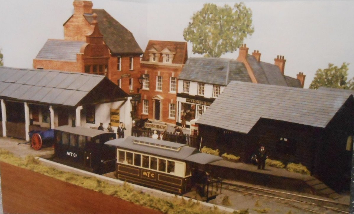
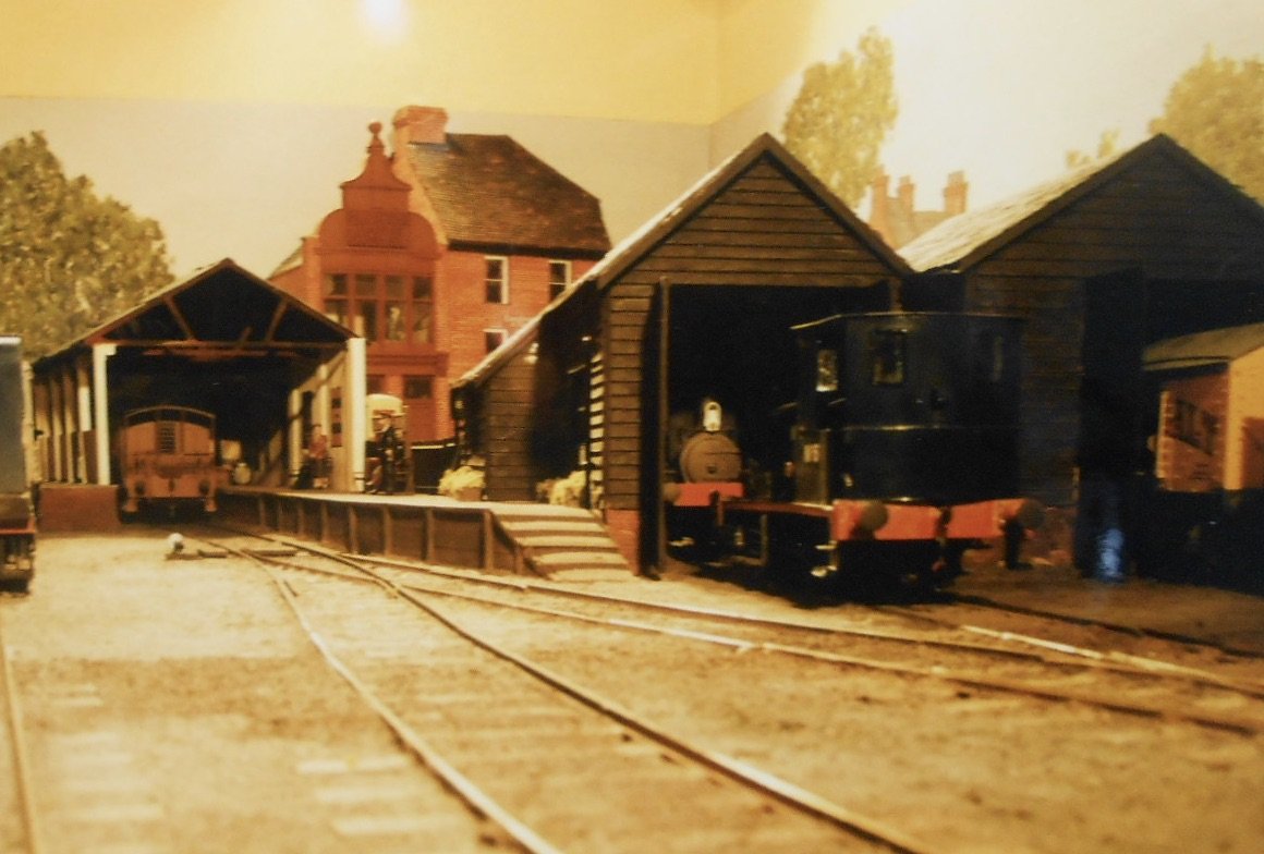
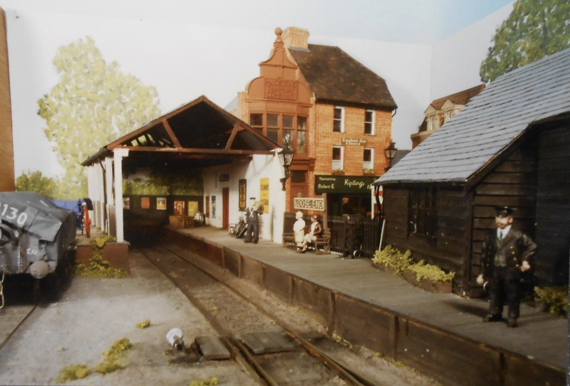
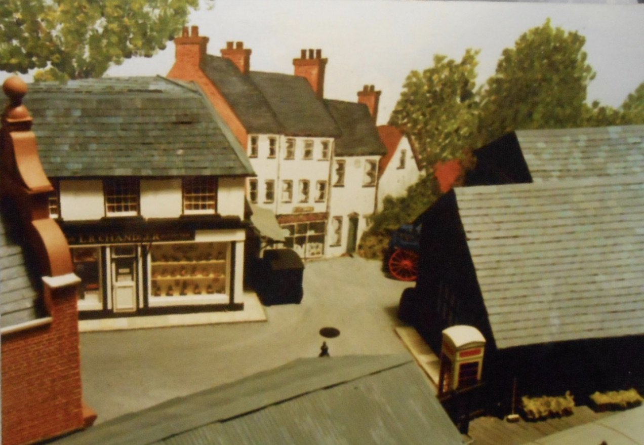
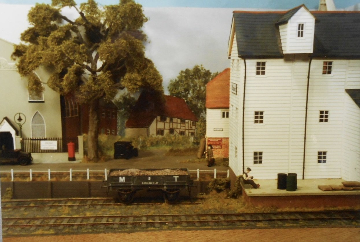
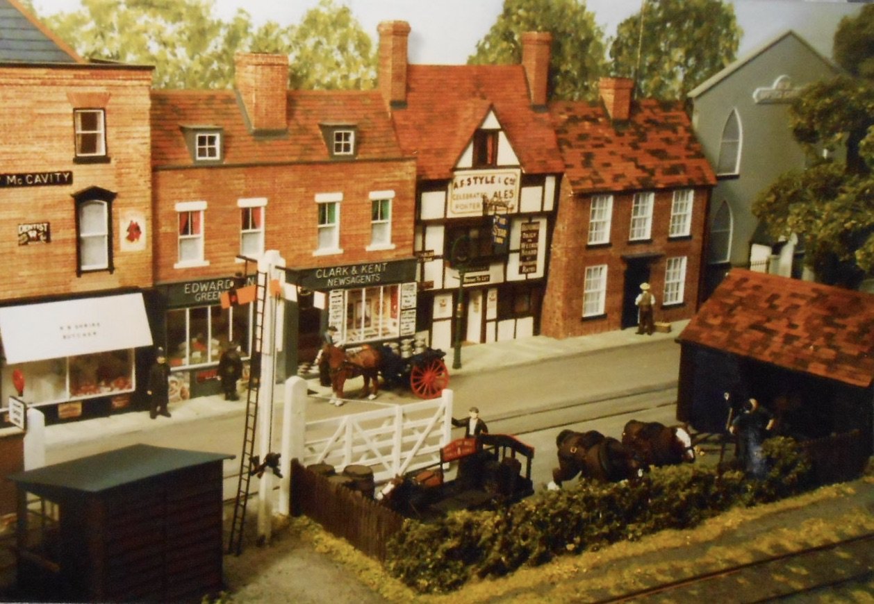
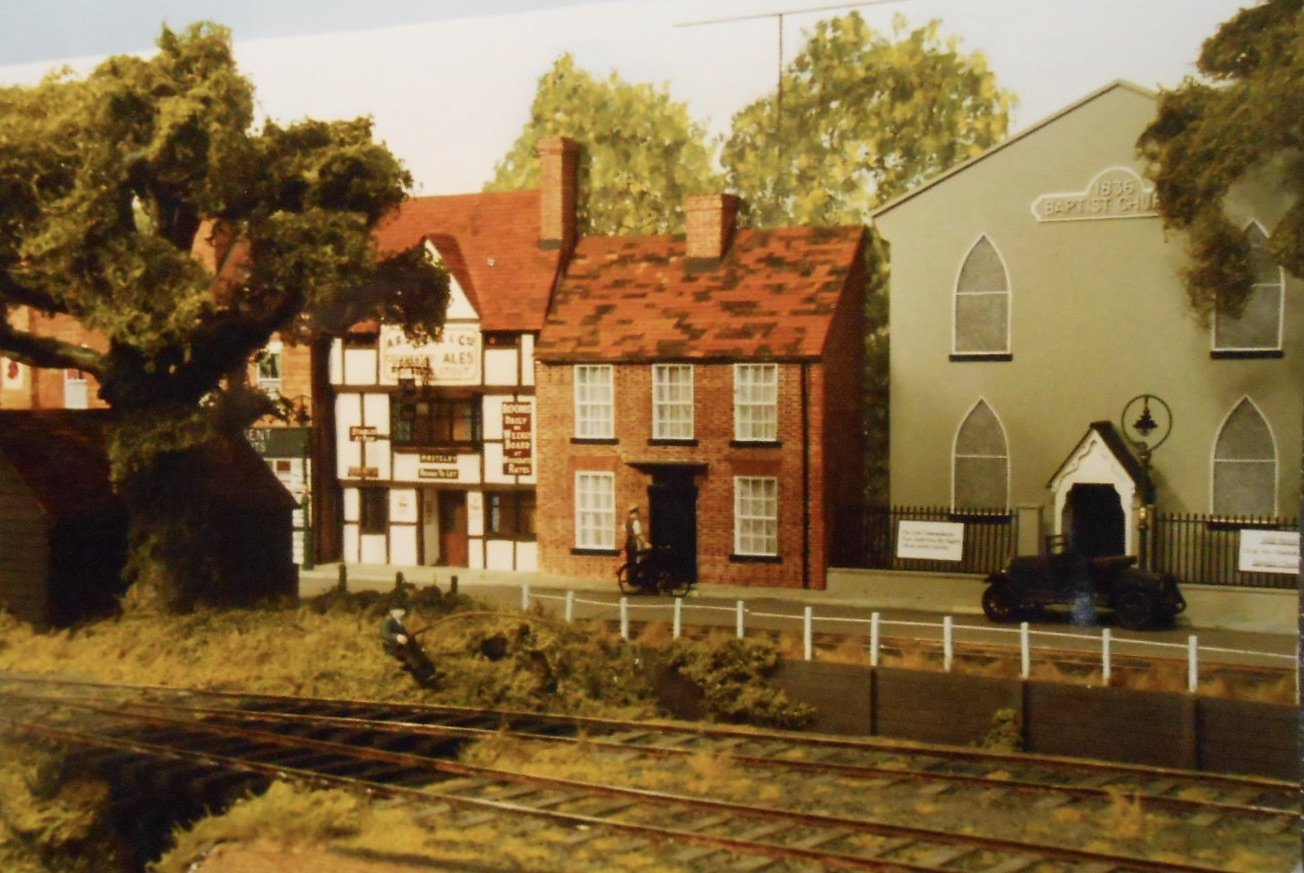
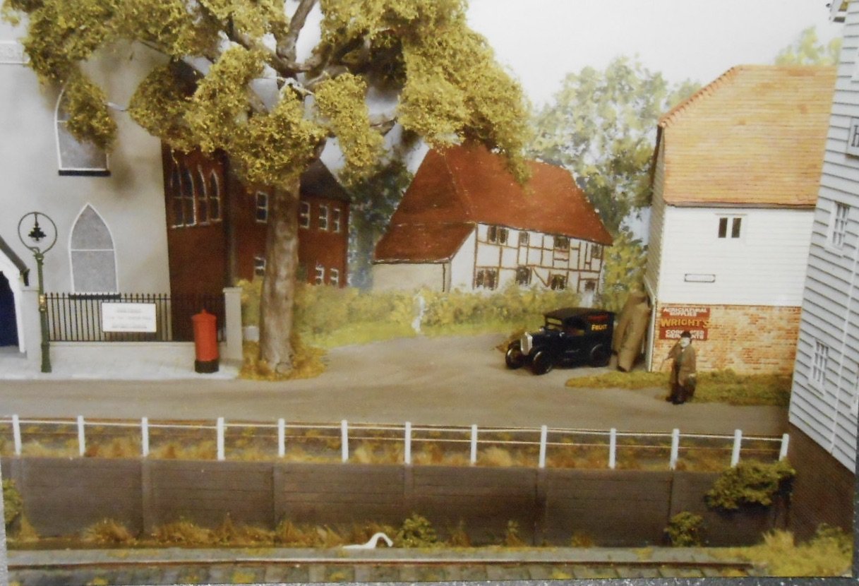
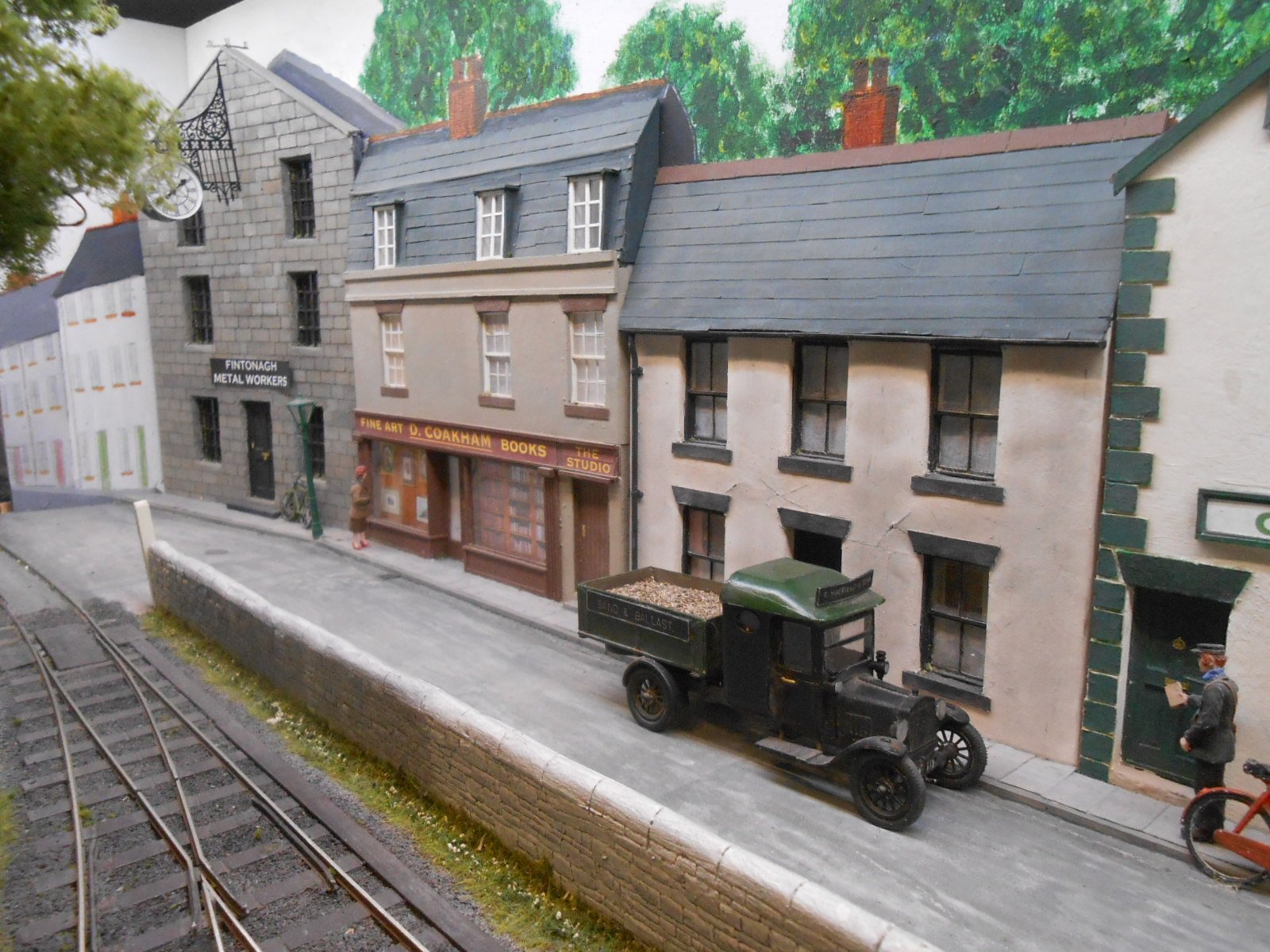
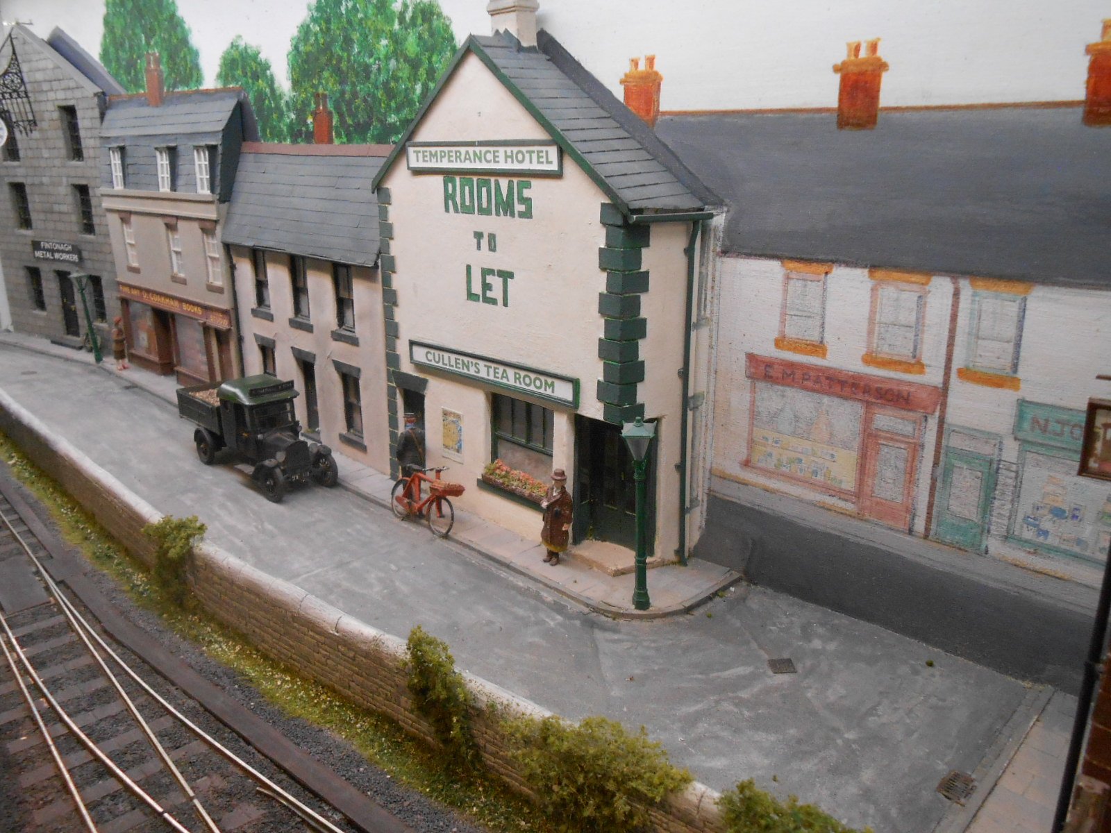
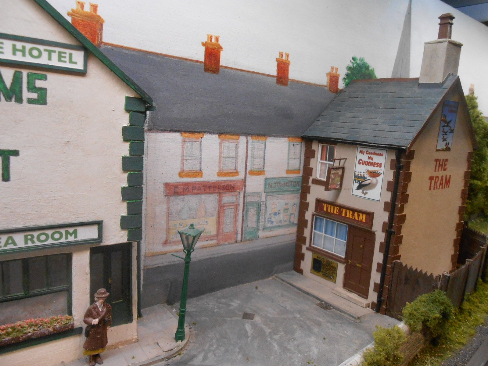
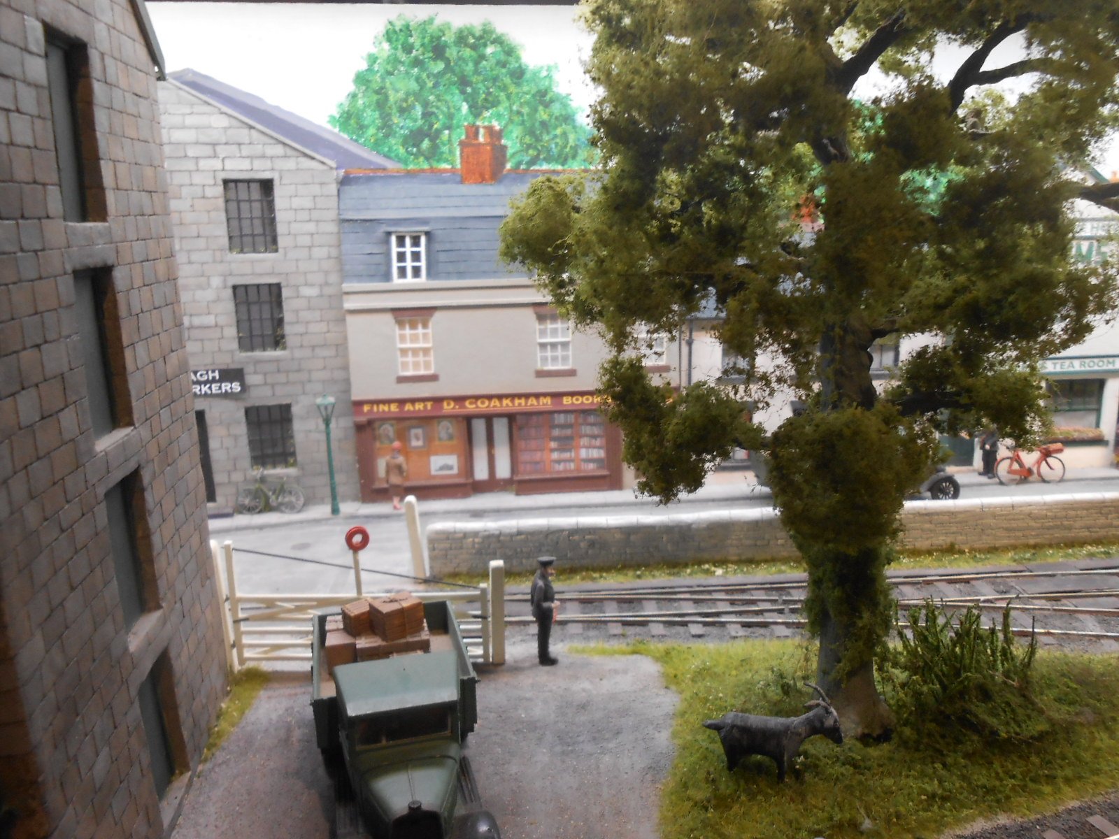
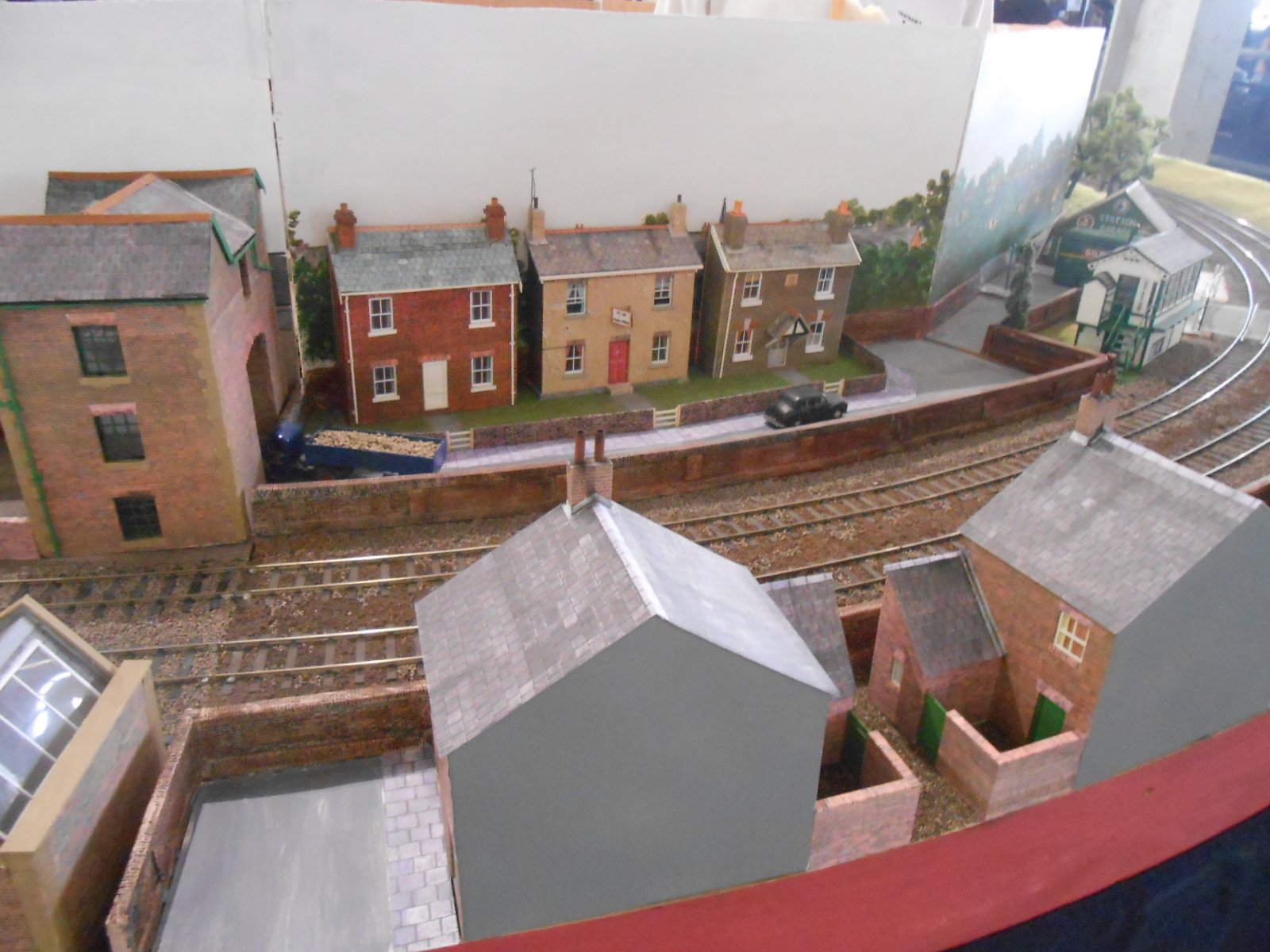
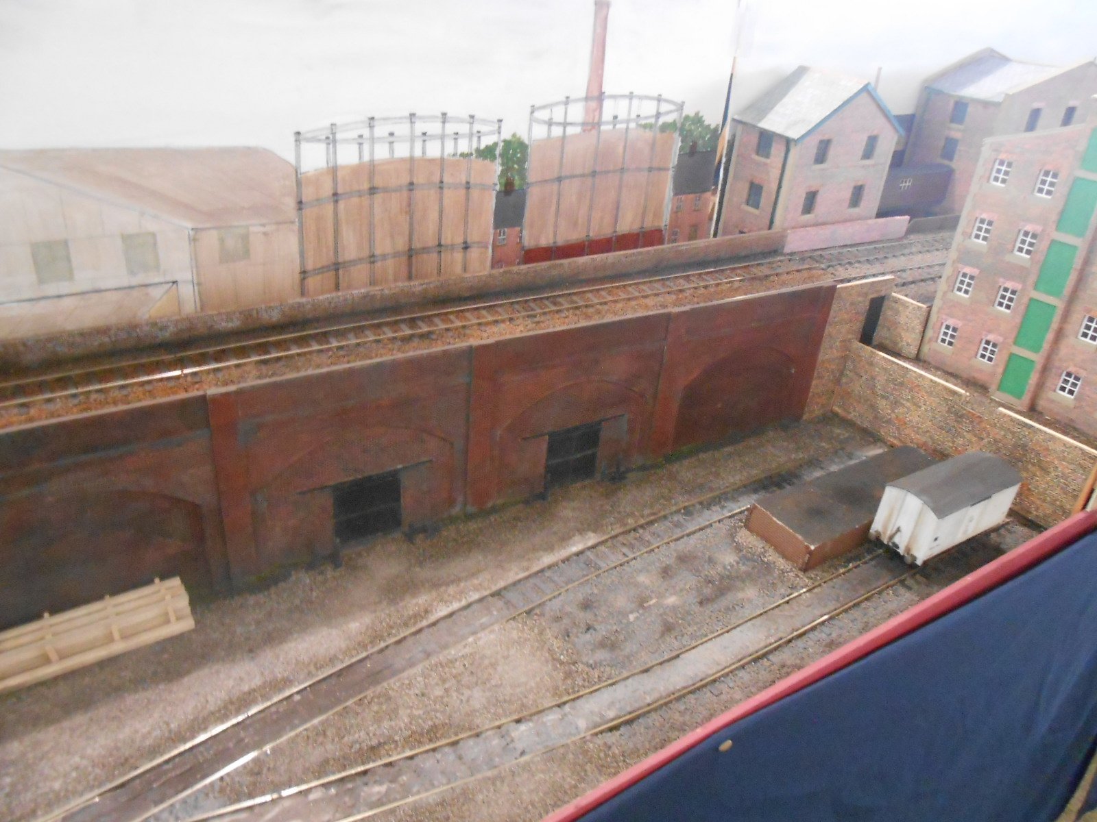
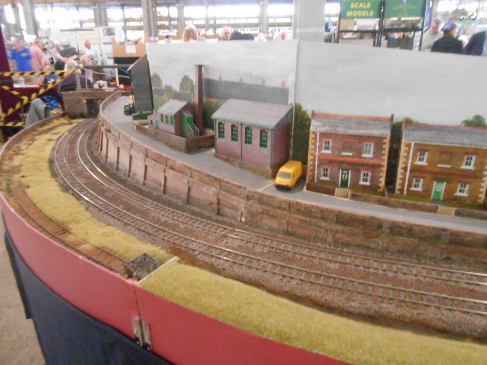
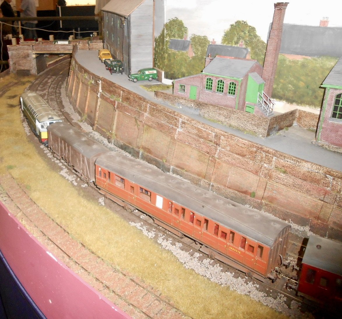
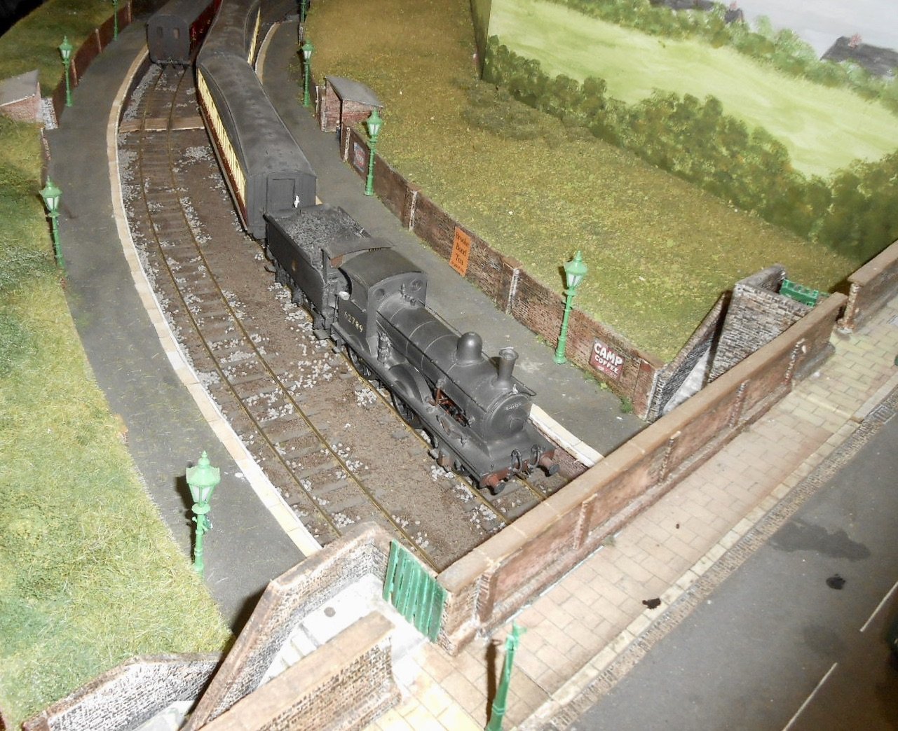
Loose End This was my first standard gauge 7mm scale layout. It was very much a Light Railway, with a mix of Colonel Stephens, Wantage, Wisbech & Upwell & Brill Tramways, to name but a few. The track plan was a mirror image of Wantage Town - ideal, as it is just over seven feet long, even in 0 Gauge. Track was Code 100 fb rail on copper clad sleepers, with points made by Marcway of Sheffield. It was built in the late '90s, so pre-digital as far as photos are concerned, but a fair few of the techniques went on to be used in my Irish layouts. Indeed, the light weight looking track even caused a few people to ask if it was broad gauge! Loose is a real village, just south of Maidstone, while the Kent & East Sussex Light Railway planned extension would have passed this way. Most of the buildings were based on actual ones in the small town of West Malling and I really went to town on the fine details, especially things like shop windows. Being Kent, there had to be an oast house of course. Locos and stock were very much based on Light Railway practice, ranging from Manning Wardles to a Wisbech tram [complete with face and Toby nameplate]. A Wantage Mathews tram was joined by other oddities as I developed my kit and scratch building skills. See what you can identify! The layout went to quite a few shows, but I could only manage about three a year in those days, due to work. Everything was [very] analogue, with wire in tube point control, three link couplings and operation from the rear. I learned a lot, not least balancing scenics in a small space via careful use of painted back scenes. Pictures below are photos of photos, so may not be the best, but overall the layout looks pretty good and worked well too. I was very pleased with the scene above, where the join between the painted road and the actual surface where the car is blends nicely. The layout was sold in the late noughties to a chap who lived near my Mum in Newark on Trent. I went on to build a small extension for him, featuring a hop garden. I also made him a Colonel Stephens railbus. Later, he sold it on & last time I heard it was living in a barn somewhere in France. By the way, an outline of my plans for a new 0 gauge layout will be appearing here soon.
- 90 replies
-
- 13
-

-

-
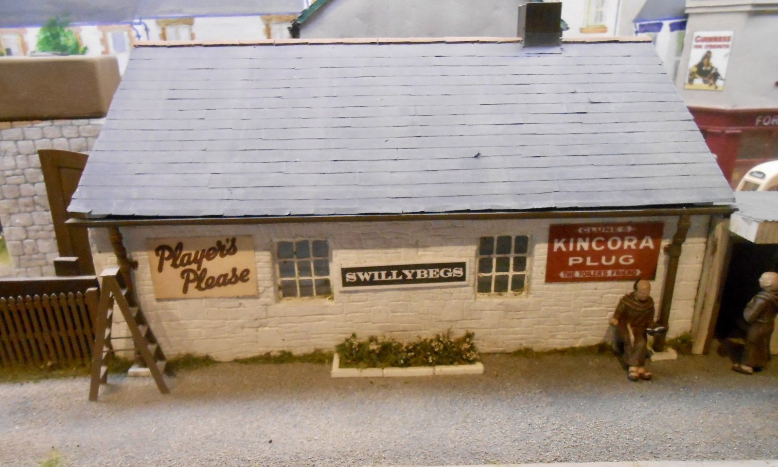
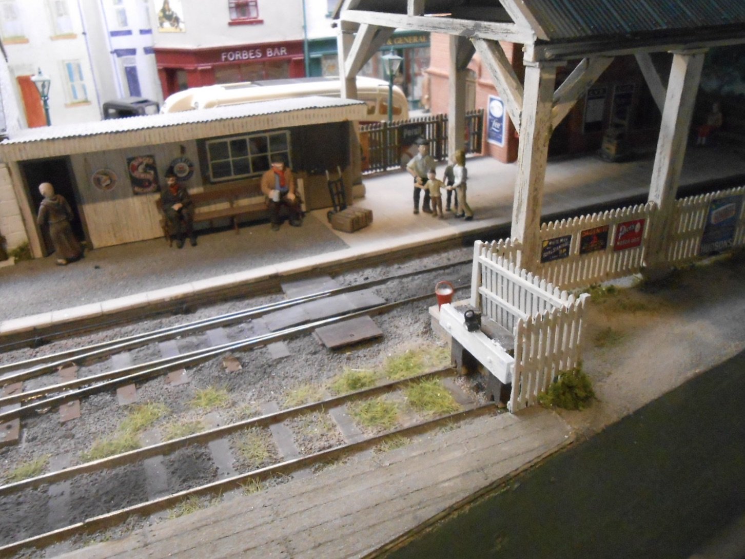
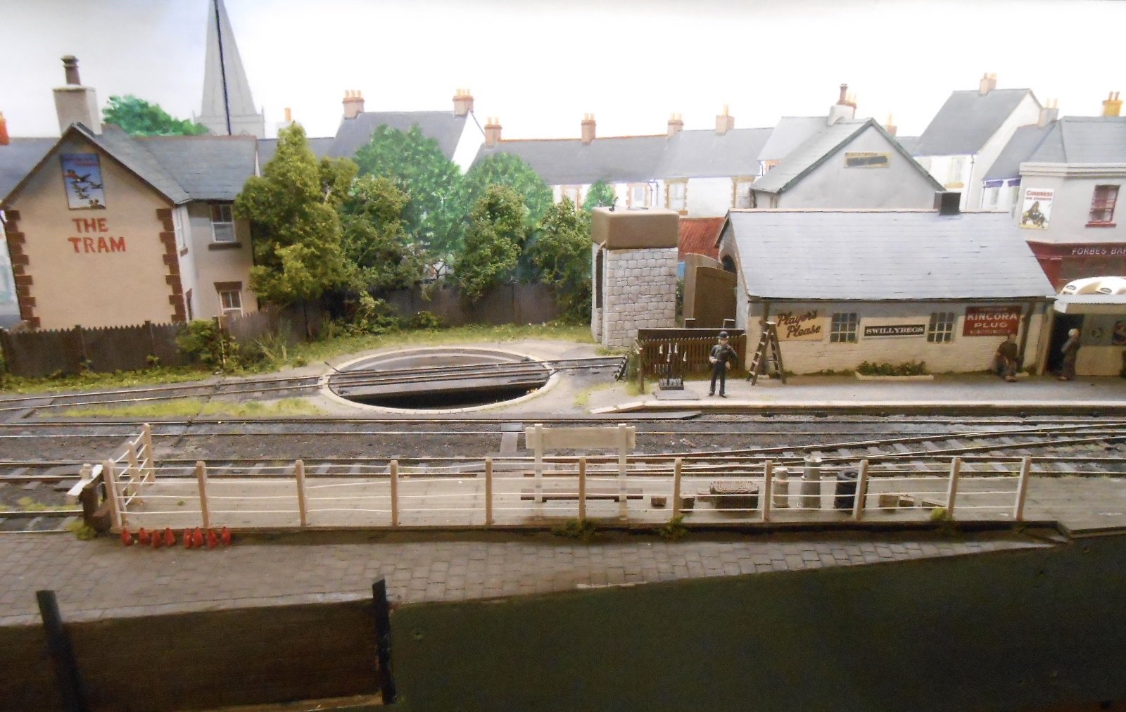
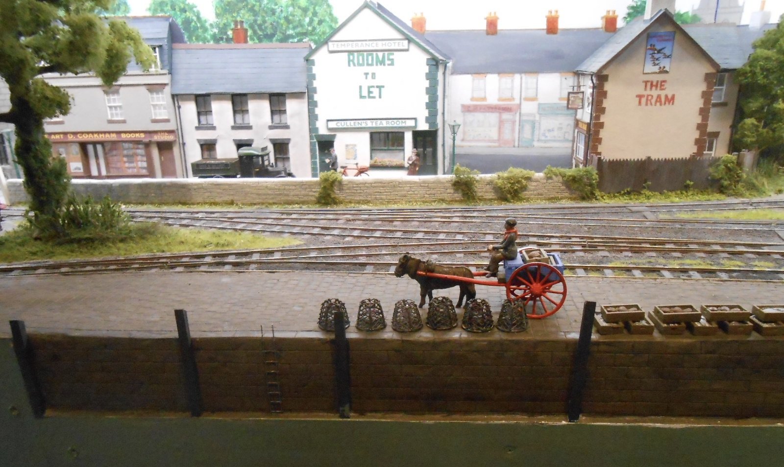
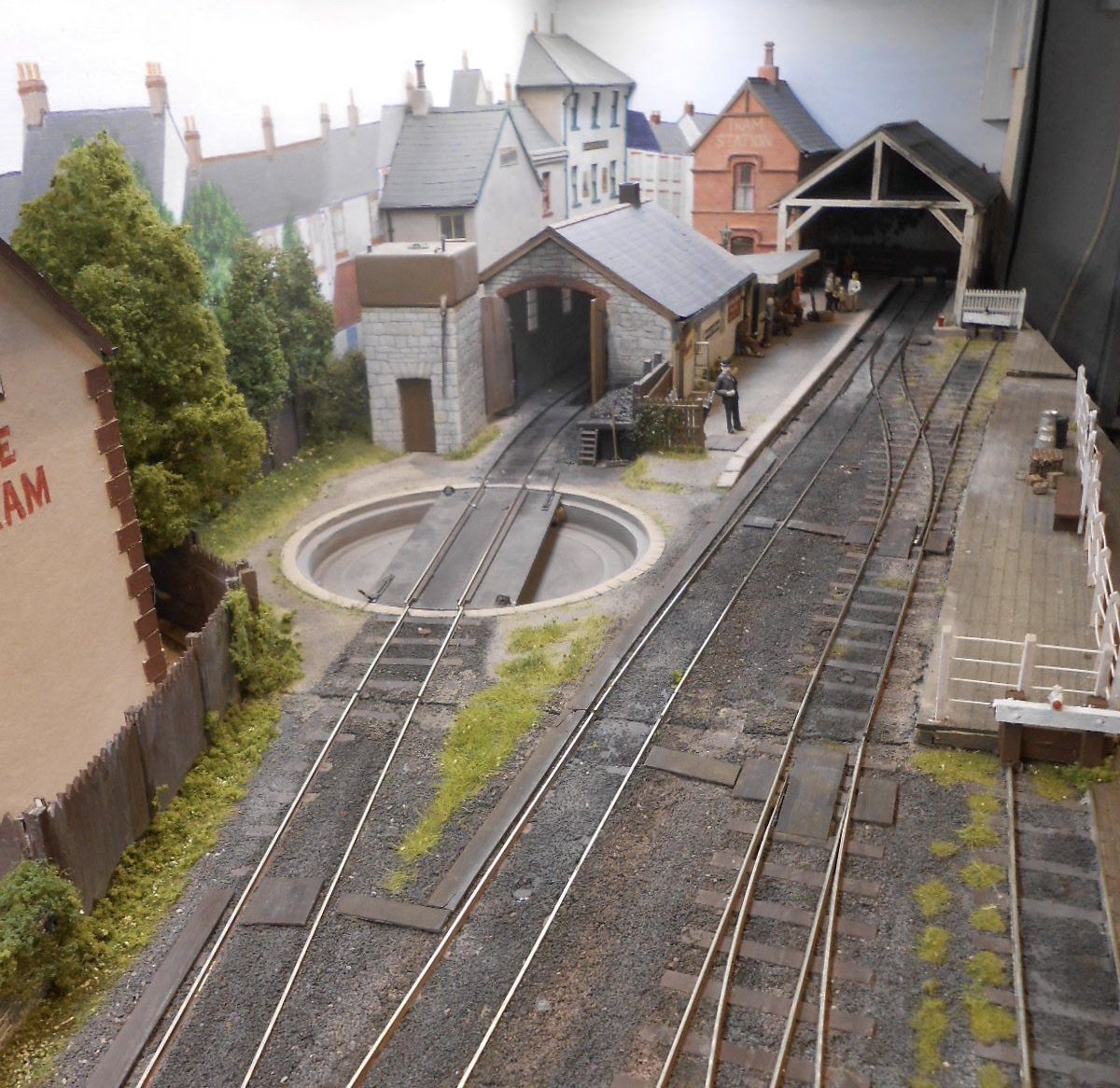
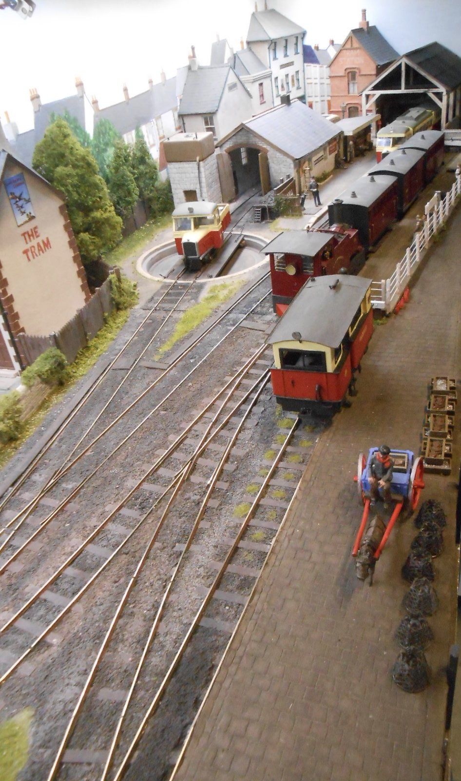
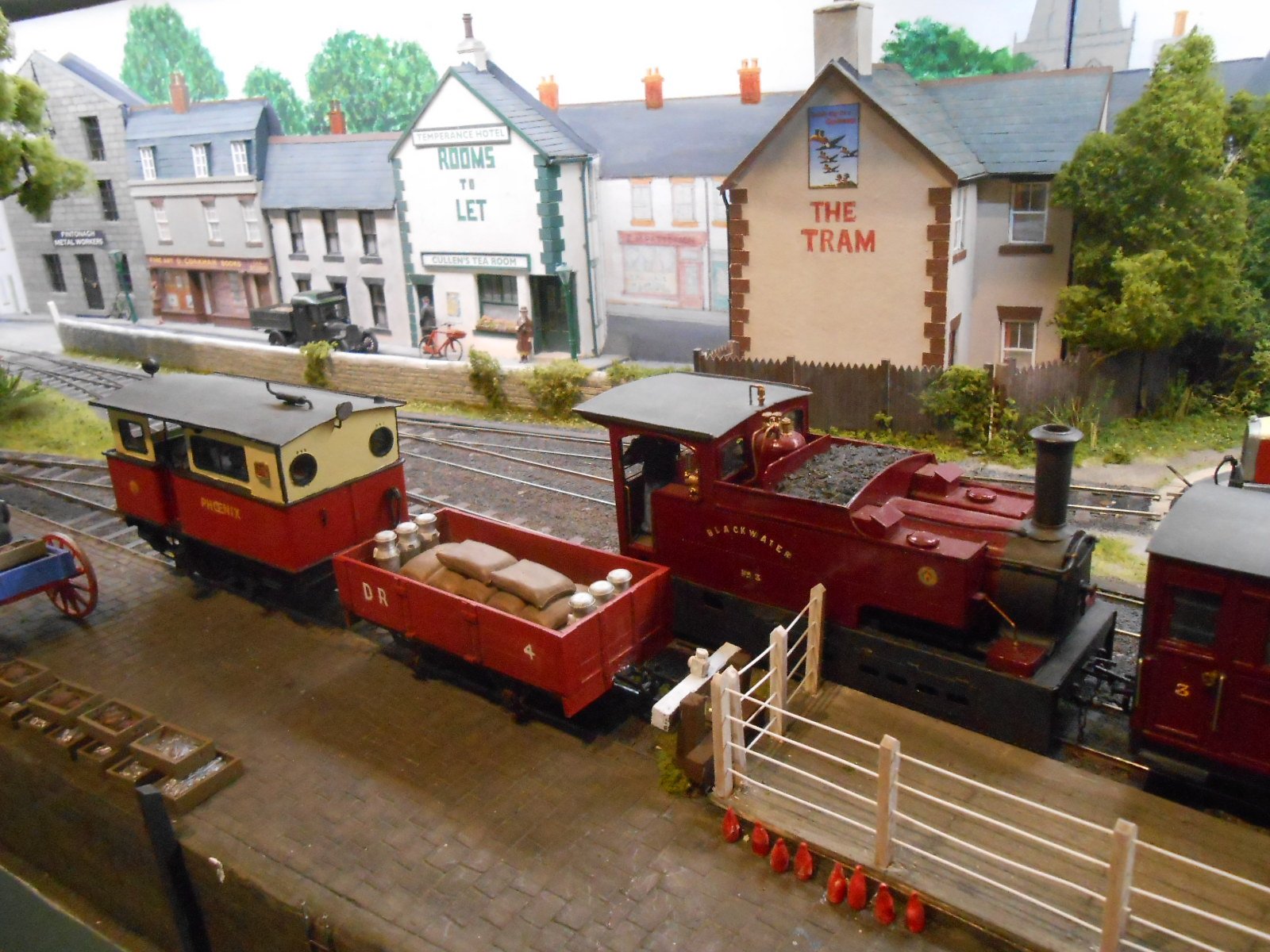
Well, you know you've been neglecting things when a layout drops off the front page and am not sure I've actually made anything since before Easter. Getting Northport Quay ready for Railex, then the Club layout ready for the Chatham Show very much part of the 'problem'... Anyway, with the Club Show now out of the way, it is at last time to get back to some of my own modelling, not least because Swillybegs is due to make its debut at the Tolworth Show in November. There's been a list of things to do for quite a while, so it has been a case of just getting on with it, starting with a new station name board. Simple enough - white on black computer print out, stuck to a board made from plastic sheet and strip New fencing next: firstly fitting 0.5mm plastic road to the posts that have been on the tramway platform for ages, then some Parkside wooden fences around the buffer stops. Then came some detailing pieces for the quayside area. Below is an overall view of the station area, including a bit of gentle fettling for the track where I had to remove permanent [rare earth] magnets & replace them with Gauge 0 Guild electric ones. You can see the new buffer stop I made [front right] too. The rest of the pictures give a tour of the layout, with Donegal stock on show, alongside the 'West Donegal Tramway' train, using former Clogher Valley loco and new coaches based on Schull & Skibbereen types. Much to my surprise, it has only taken a few days to sort out the bits and pieces. So, overall, the scenic work is done. What needs to happen now is to make sure everything runs well, both all the newly built stock and the original CVR stuff. Much of the work revolves around getting my home made 'chopper' couplings working properly. Playing trains, in other words! However, planning for a new project is also getting under way, for which you will have to keep an eye on the 'David's 0 Gauge Stuff' thread in the British Outline Modelling section.
- 43 replies
-
- 22
-
-
-
Just go on YouTube and type in Chatham Show 2025. There are numerous videos, including one over two hours!
-
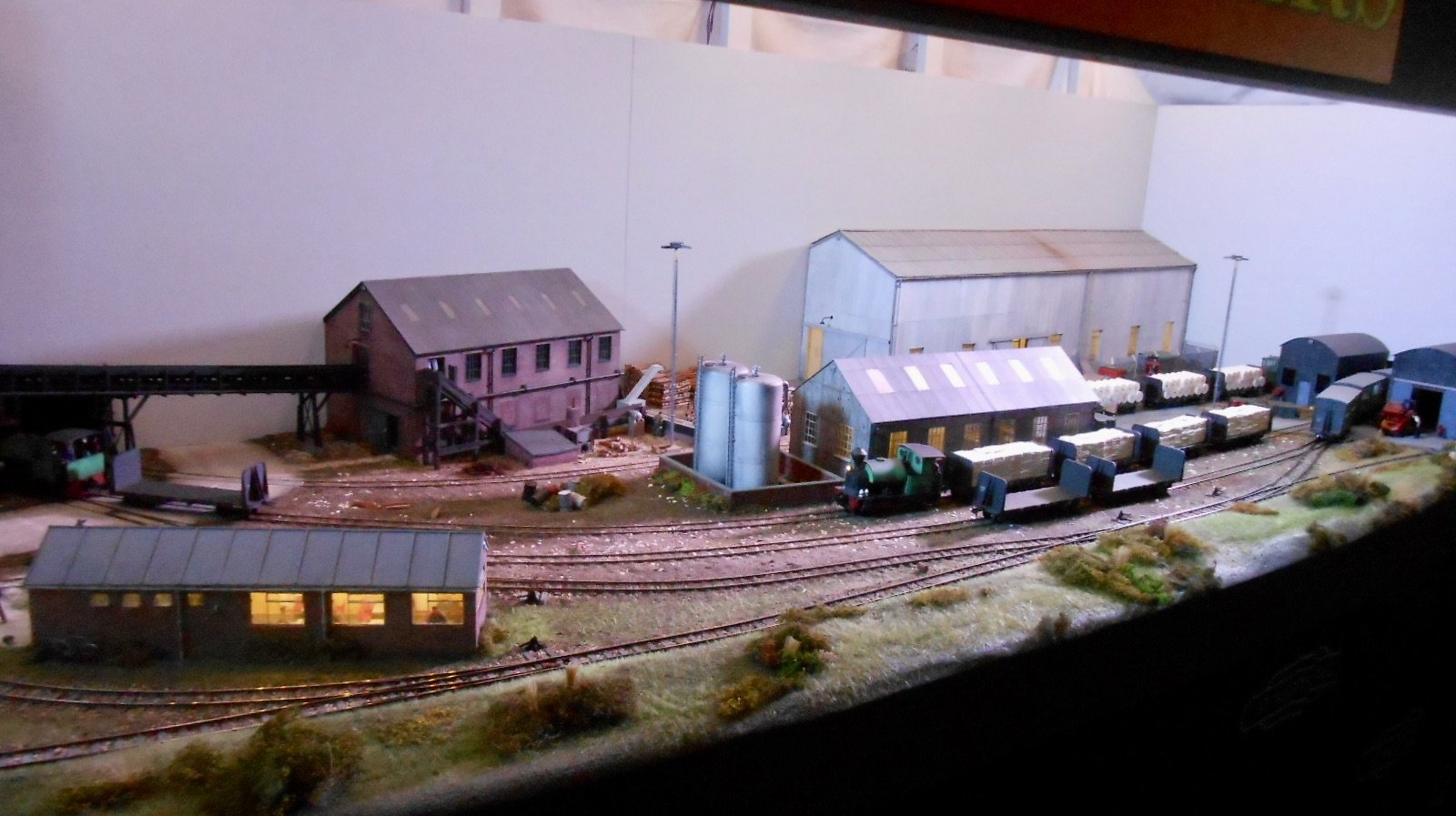
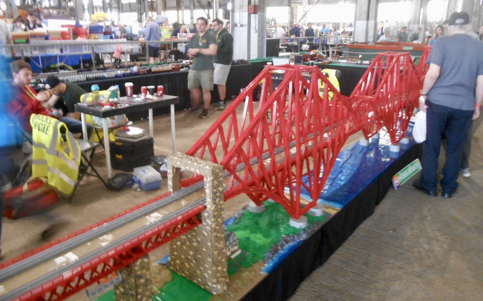
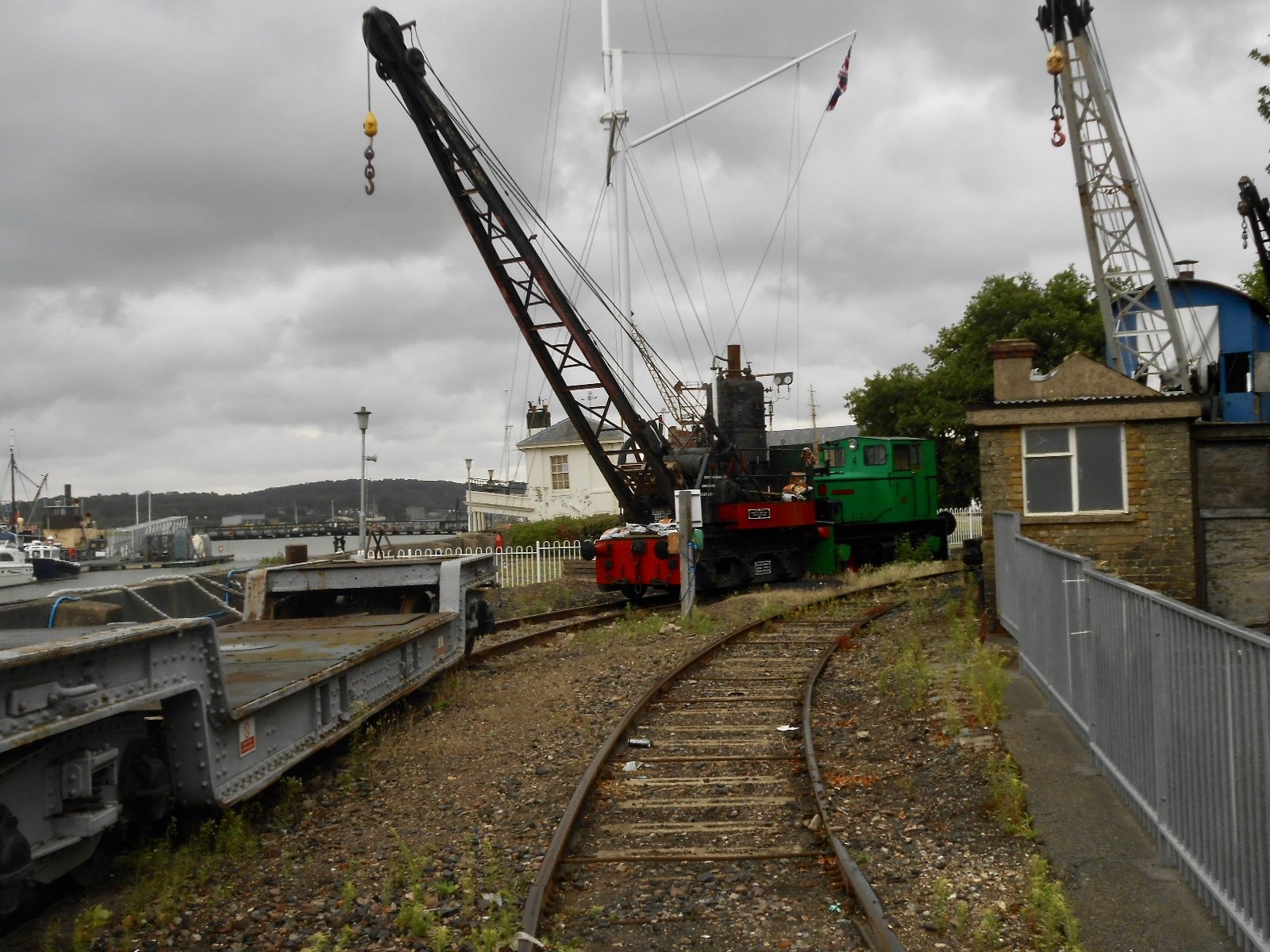
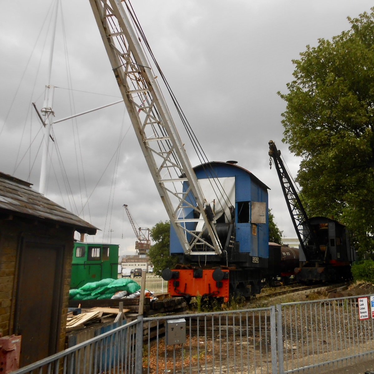
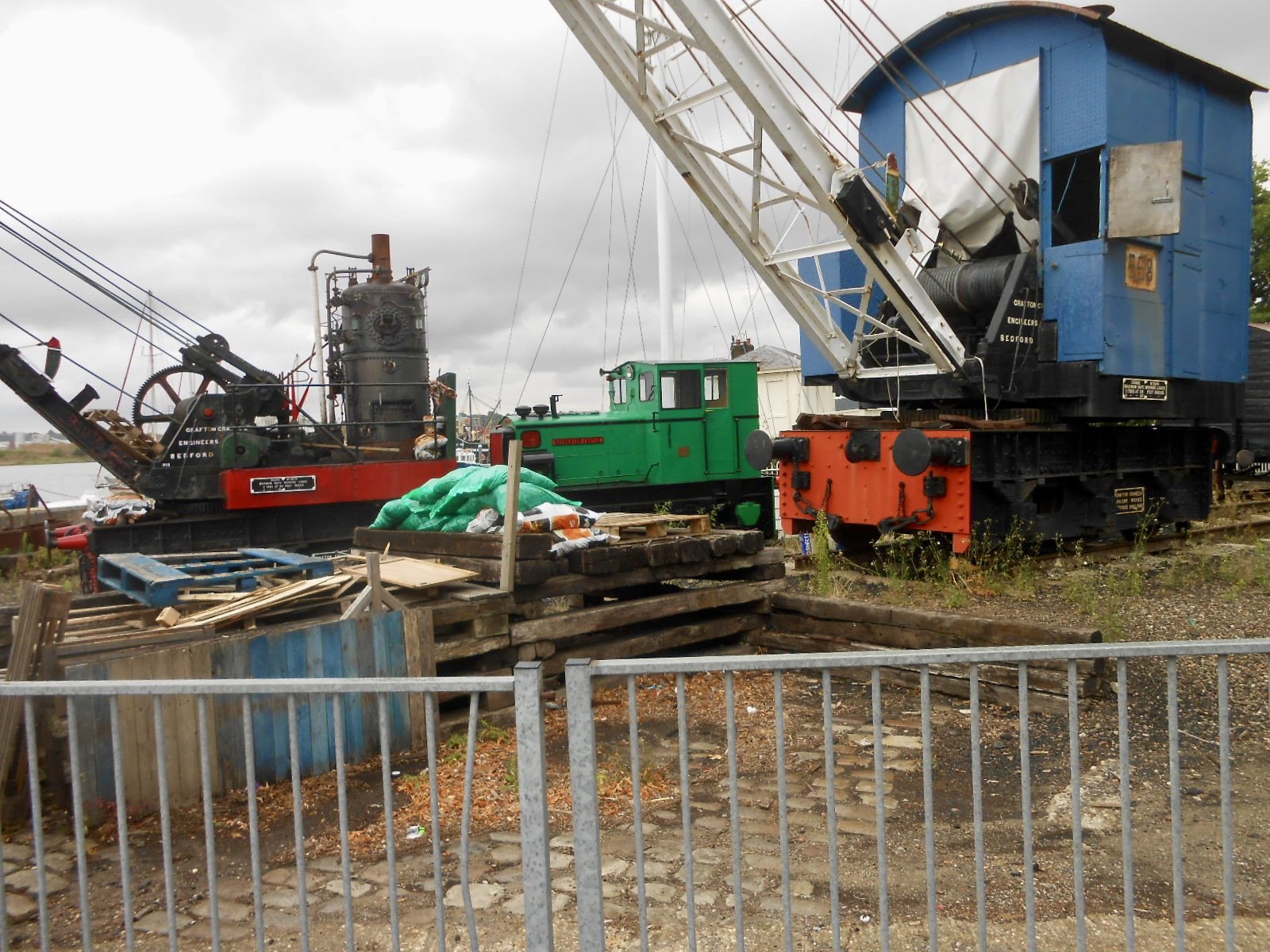
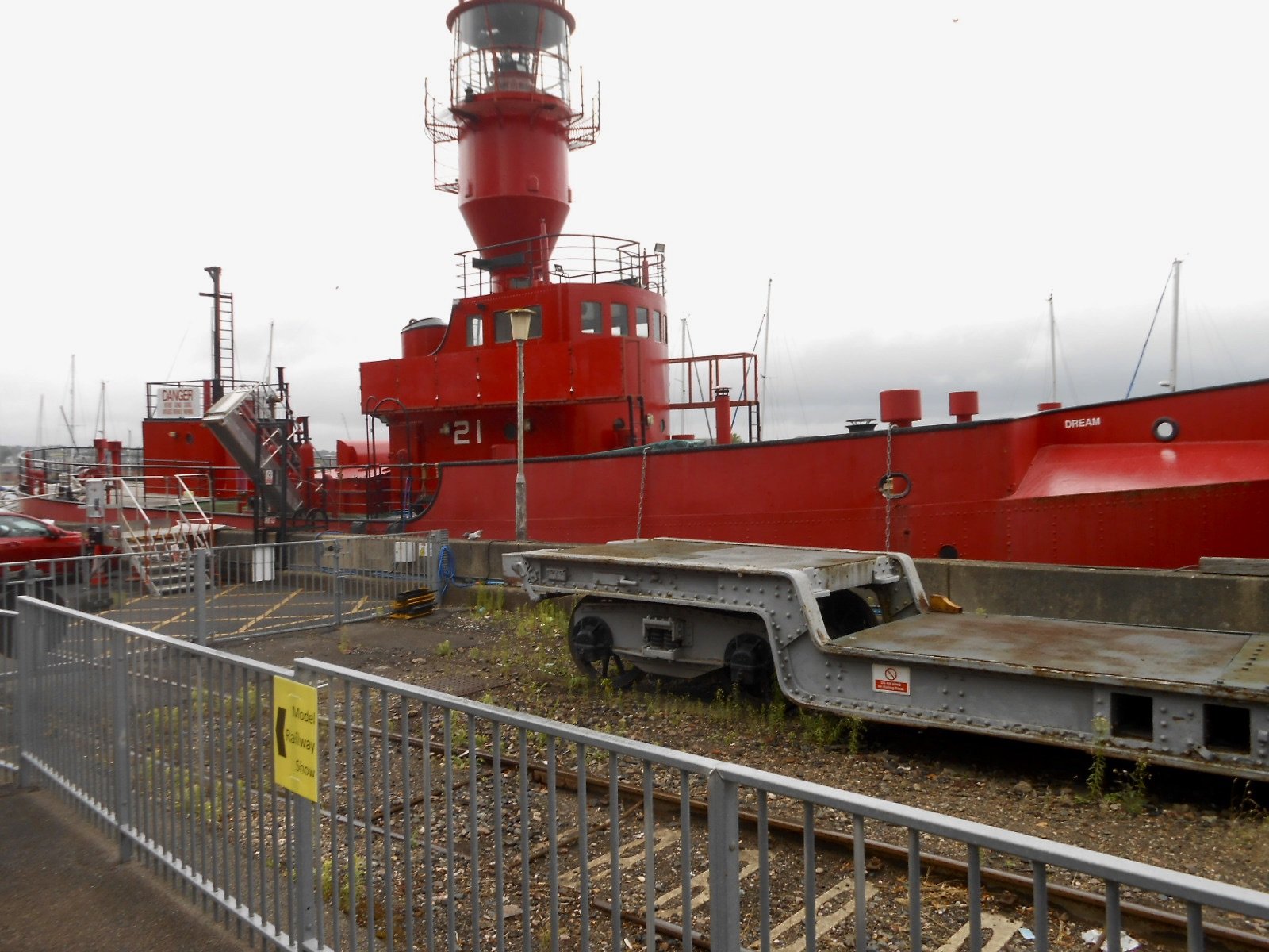
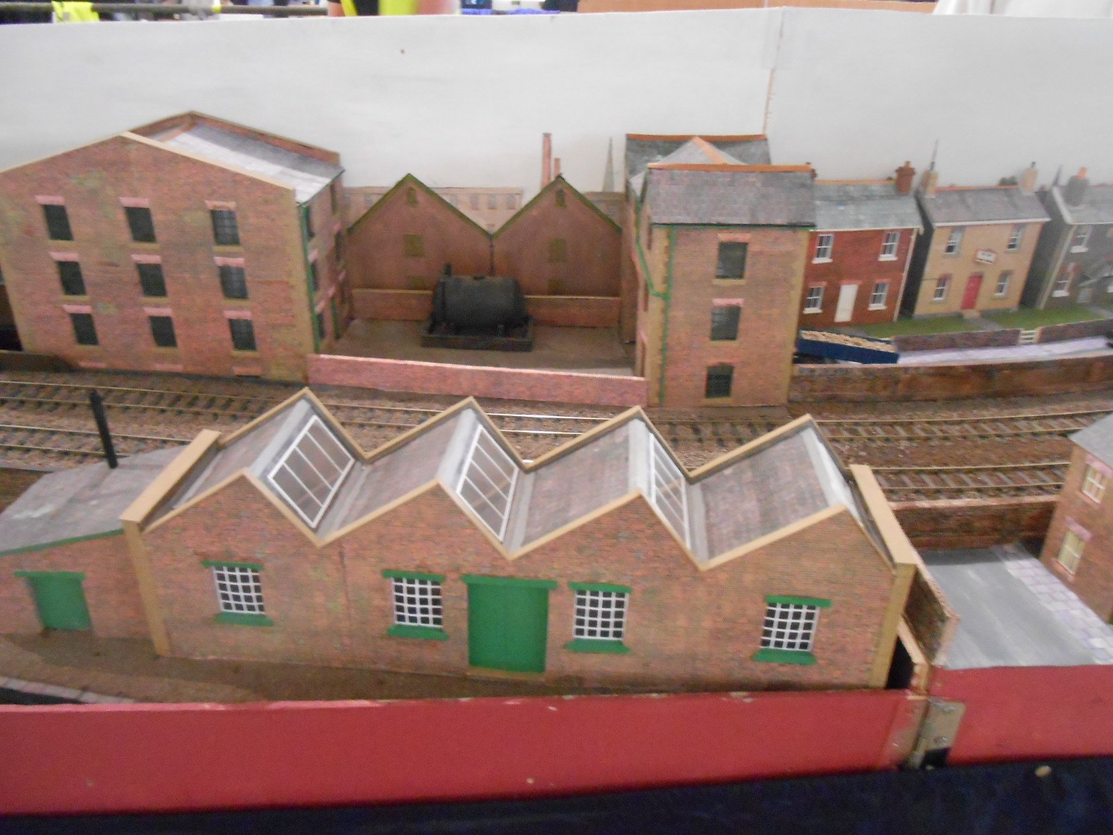
Overall a decent weekend for the Club, with over 2300 visitors, up around 200 on last year, despite [or maybe because of] the weather. Feedback from both exhibitors and traders has been positive, with the only negatives being about the poor lighting. With the weather being so gloomy at times, any layout without its own lighting was at a real disadvantage, because the Covered Slip relies more on its skylights than any artificial means. Indeed, very few of the pictures I took on Sunday [while acting as one of the layout judges] are worth showing here. Suffice to say that the standards were high, regardless of scale & gauge. James Street, in the current Modeller, is certainly very impressive, but we gave the 'Best Layout' award to the St Neot's Club's "Bowaters", a beautiful rendition of the Paper Mill in Sittingbourne. My photo really doesn't do it justice! Runner up was the remarkable Lego layout of the Forth Bridge. All of the trains are made from Lego too and are very much identifiable as the real thing. I took a few pictures of the mobile cranes, which may be of interest. Plus the Lightship, which has recently appeared near the wonderfully named Thunderbolt Pier. Vic 96, the little victualling ship, has recently moved here too. So, lots to see and well worth a visit. There are several videos of the show now posted on the web, including YouTube. Will post some addresses later - unless anyone wants to get in first!
-
While you are at this stage, Alan, am interested to know about the square cut out in the chassis to take the hornblocks. Can't remember seeing the rationale behind these, but am assuming they don't have to be majorly accurate in terms of their width, because they only get soldered in place once wheels and rods are fitted? Height a different matter, because the top of the cut out is the limit of vertical movement of the compensation? While I'm here, apologies to Patrick, as I saw you were using 0n16.5 track and immediately thought 7mm scale. A quick check on the calculator shows me that 5.5mm/ft is 1:54.45, as opposed to 1:43 - so gradually moving up the sizes...
-
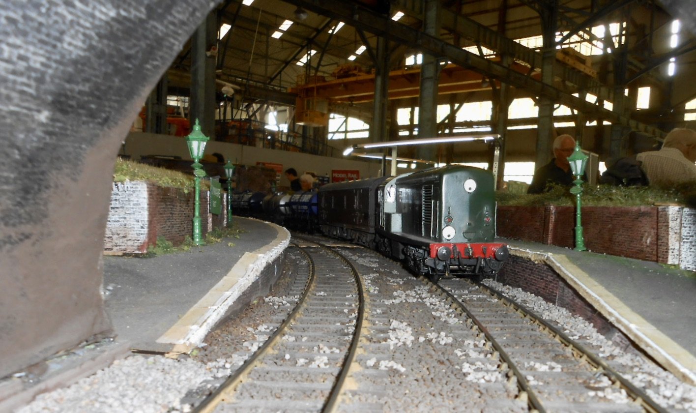
Thanks Alan. We had over 2300 visitors at the show and on the Club layout, most of my stock ran really well - especially as most of it had been in boxes for the last ten years. The Type 1 diesel, E4 2-4-0, J69, DMU and 08 shunter ran all weekend racking up a whole kilometre each over the two days. When we switched to dcc, the B17 and F5 also performed nicely. Indeed, it was very rewarding to get these models out again and am really tempted to build a new layout to run them at home from time to time. However, work on the Irish projects beckons and am looking forward to getting back to some modelling again, especially with all the inspiring stuff on this forum .
-
I'm sure garages should be renamed Railway Room. Far better use for them, as long as there is a driveway to park the car.
-
Well, the worst of the amber warning for thunderstorms passed us by, though it was a pretty dark and soggy morning nonetheless. However, in some ways better than bright and sunny, because if the weather is poor at this time of year, you are more likely to seek out an indoor venue than go to the seaside... Considering I supplied around 80% of all the stock on the layout, most of it ran well, though it took most of the morning to work out what trains went best with each loco. In the end, despite hoping to run 7-8 coach passenger trains and 20 wagon goods, we had to settle for half that, mainly because the uneven floor in our area resulted in a significant gradient around part of the circuit. Once that was organised we had four trains in each direction doing 2-4 circuits. Doesn't sound much, but at around 100metres that is about half a day's work on a short terminus-fiddle yard layout. The photos below are just of North Circular, because I was on duty most of the day. As I'm one of the judges for the 'best layout' awards, this should be a good opportunity for pics of the rest of the show tomorrow. Apologies for the shortage of trains - the light was so poor, I was down to a shutter speed of 1/8 of a second!
-
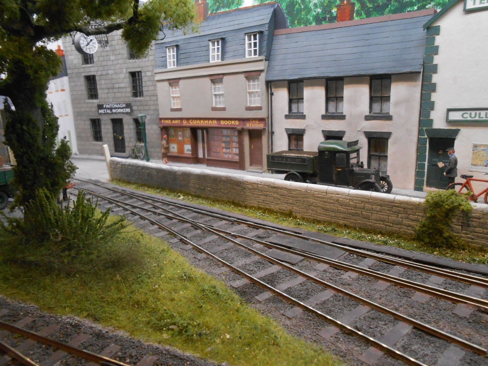
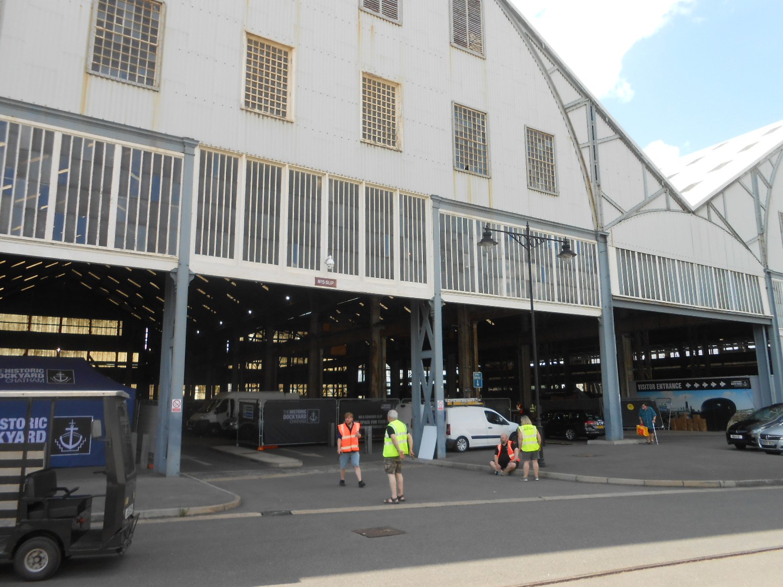
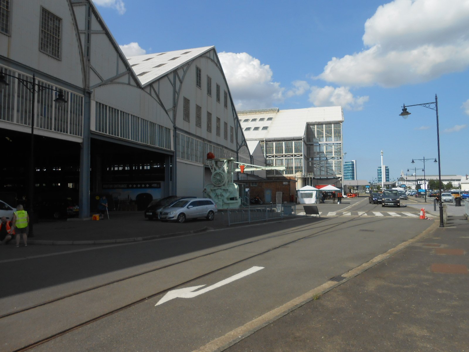
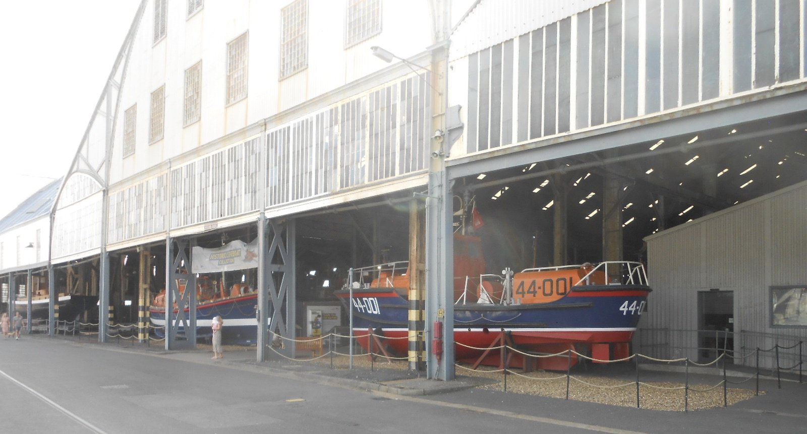
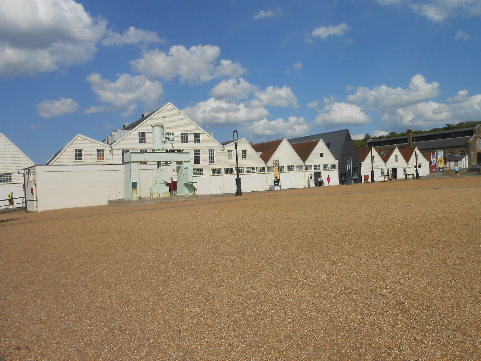
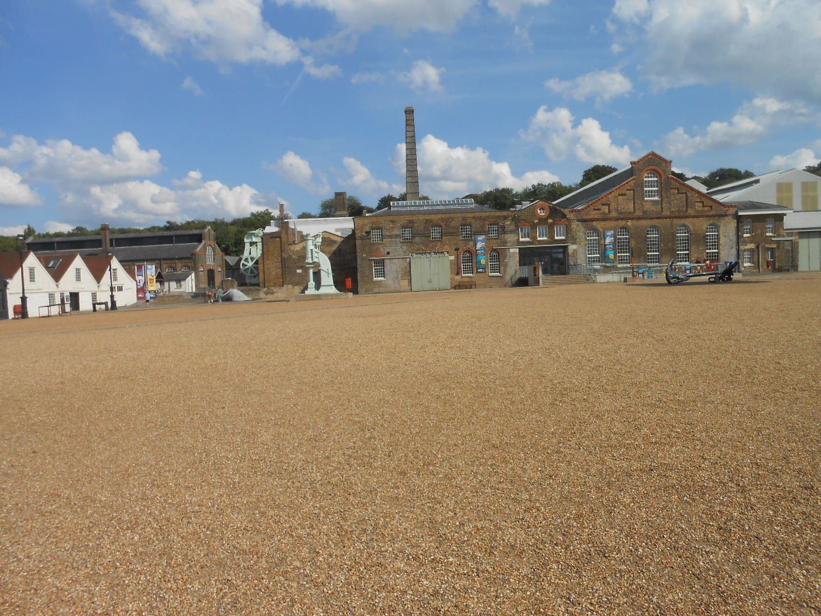
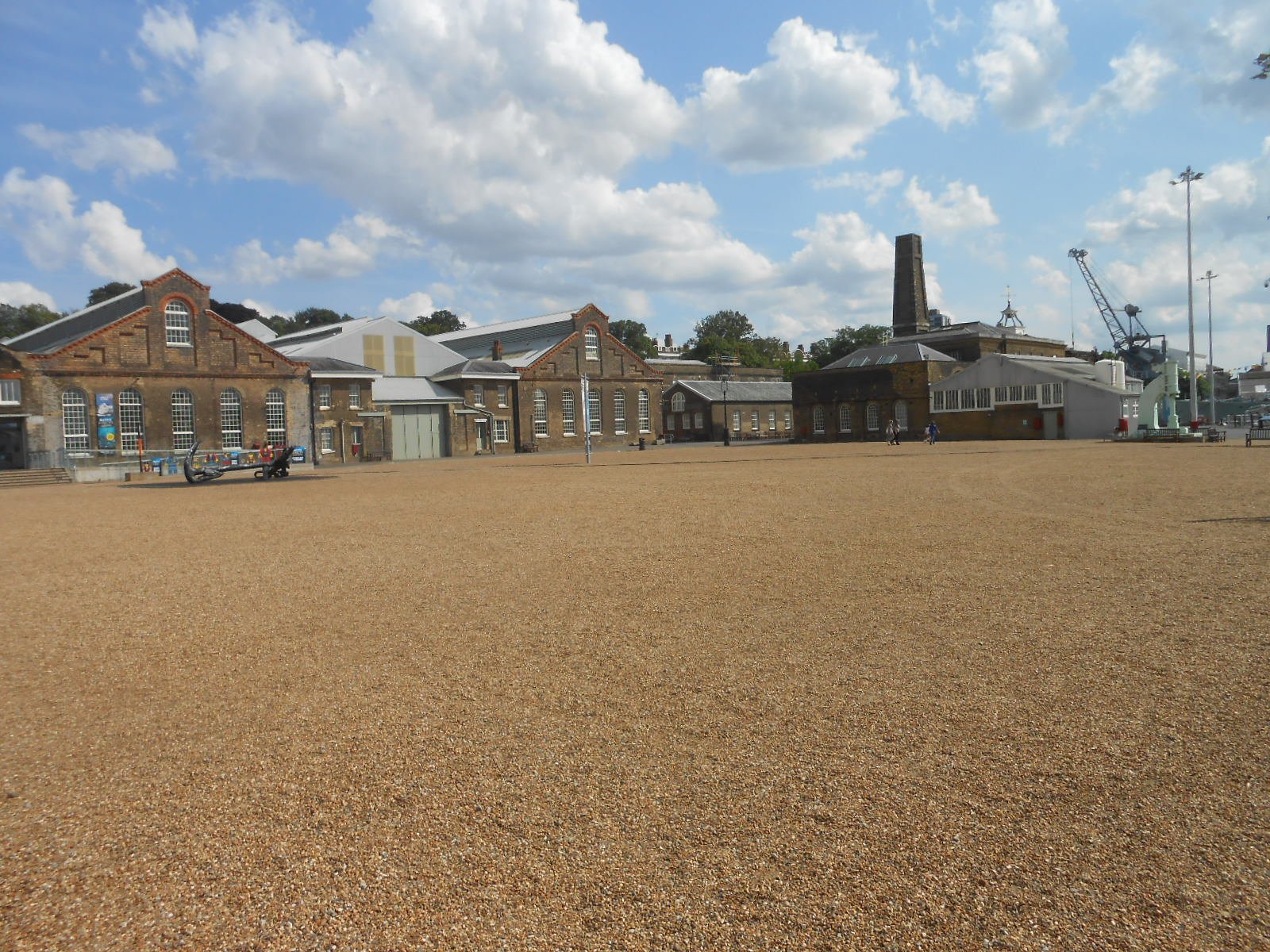
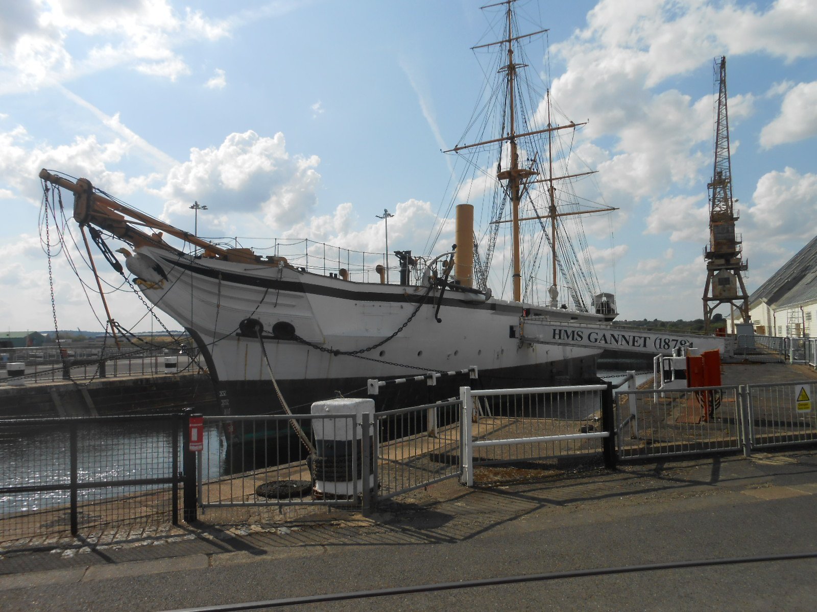
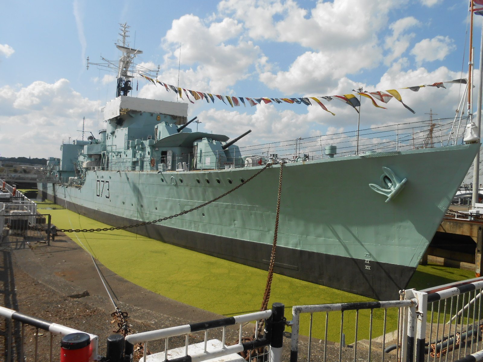
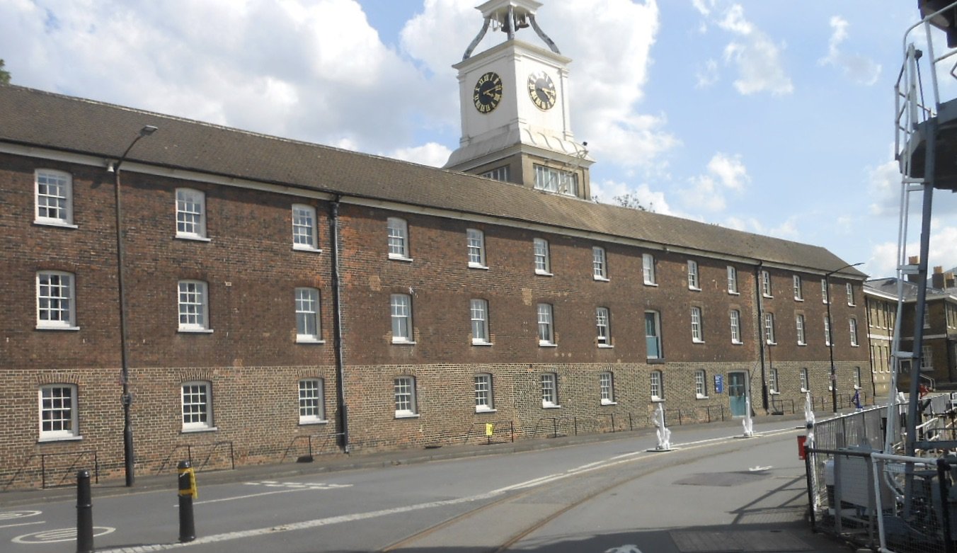
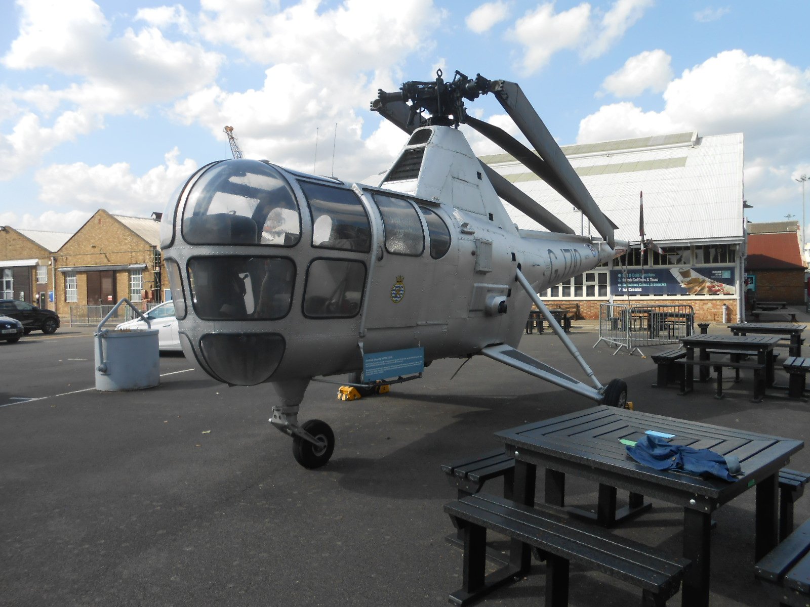
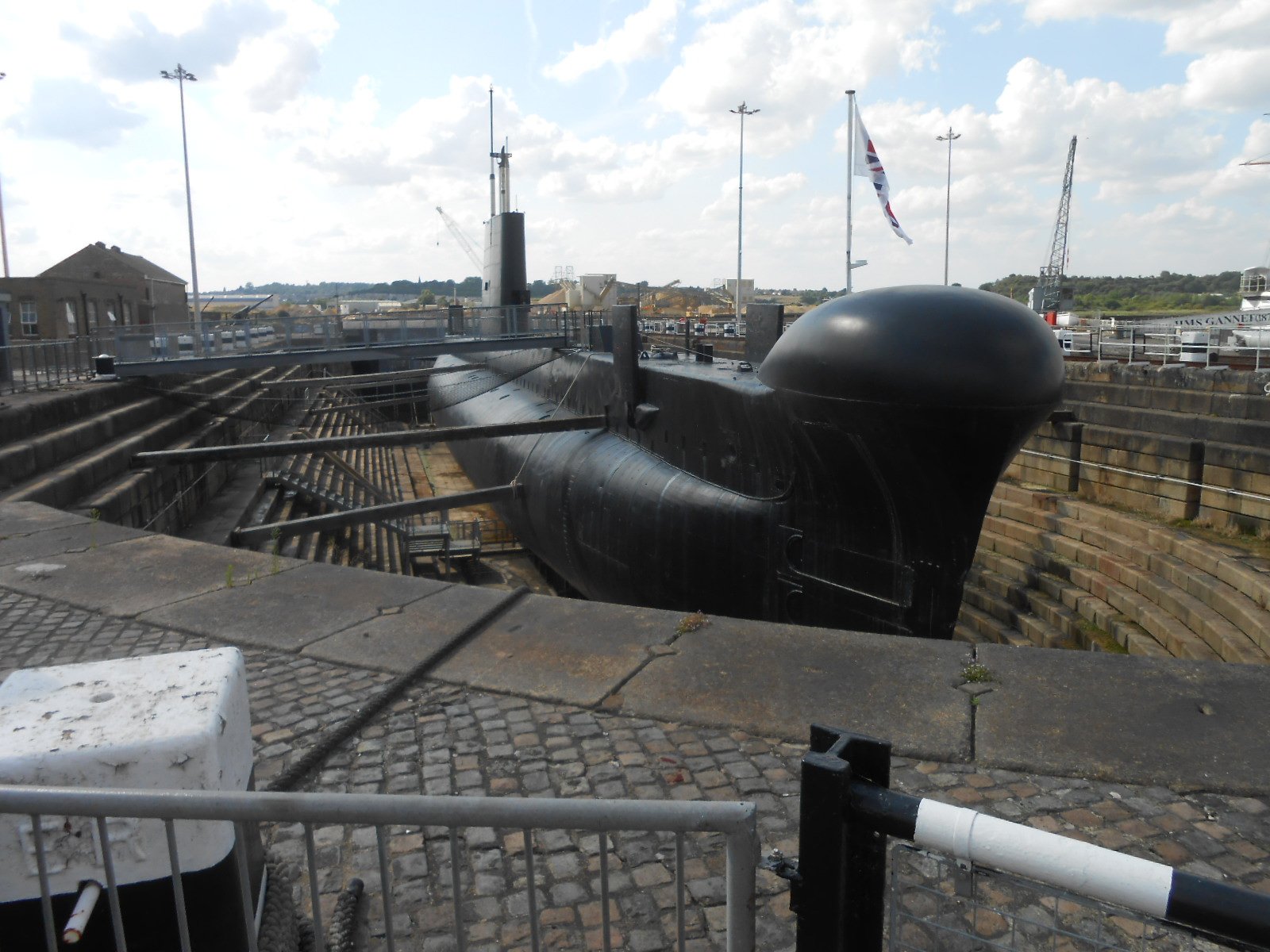
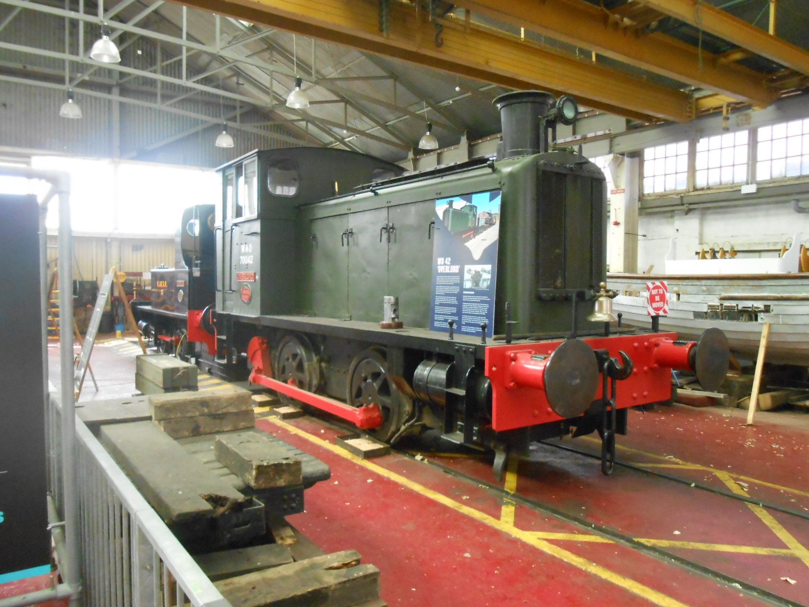
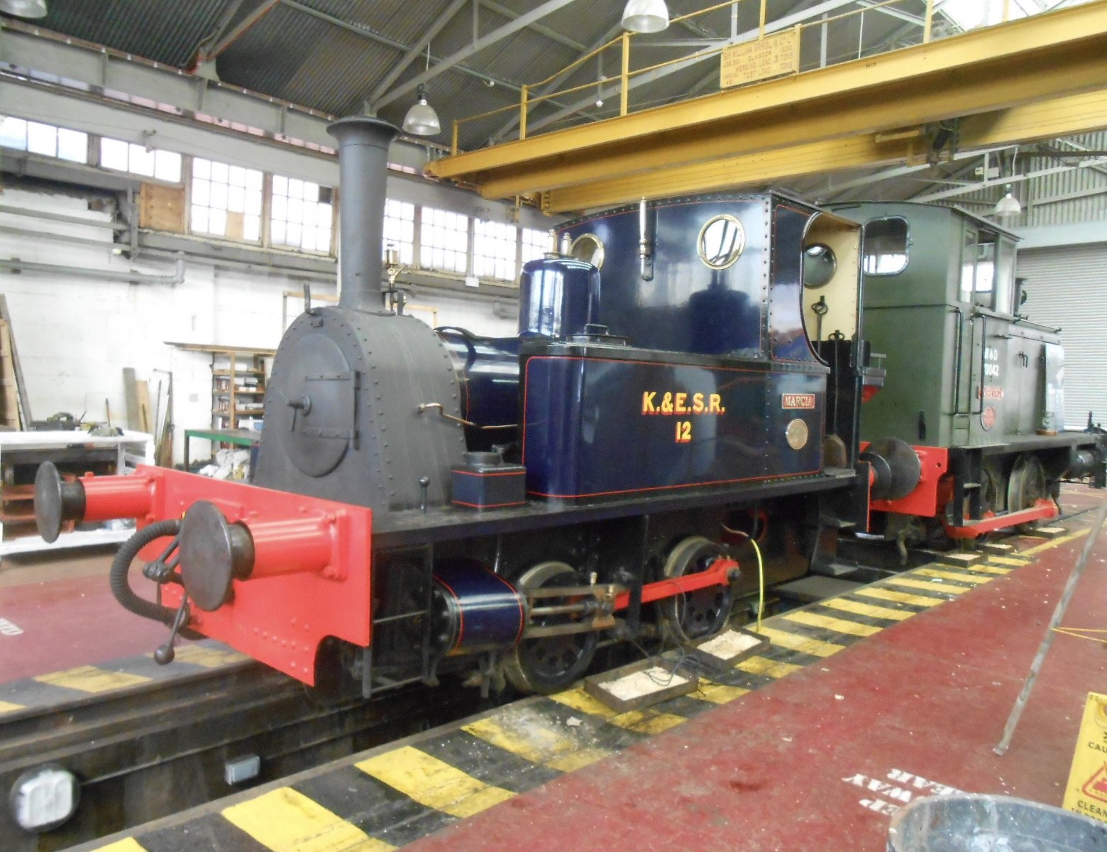
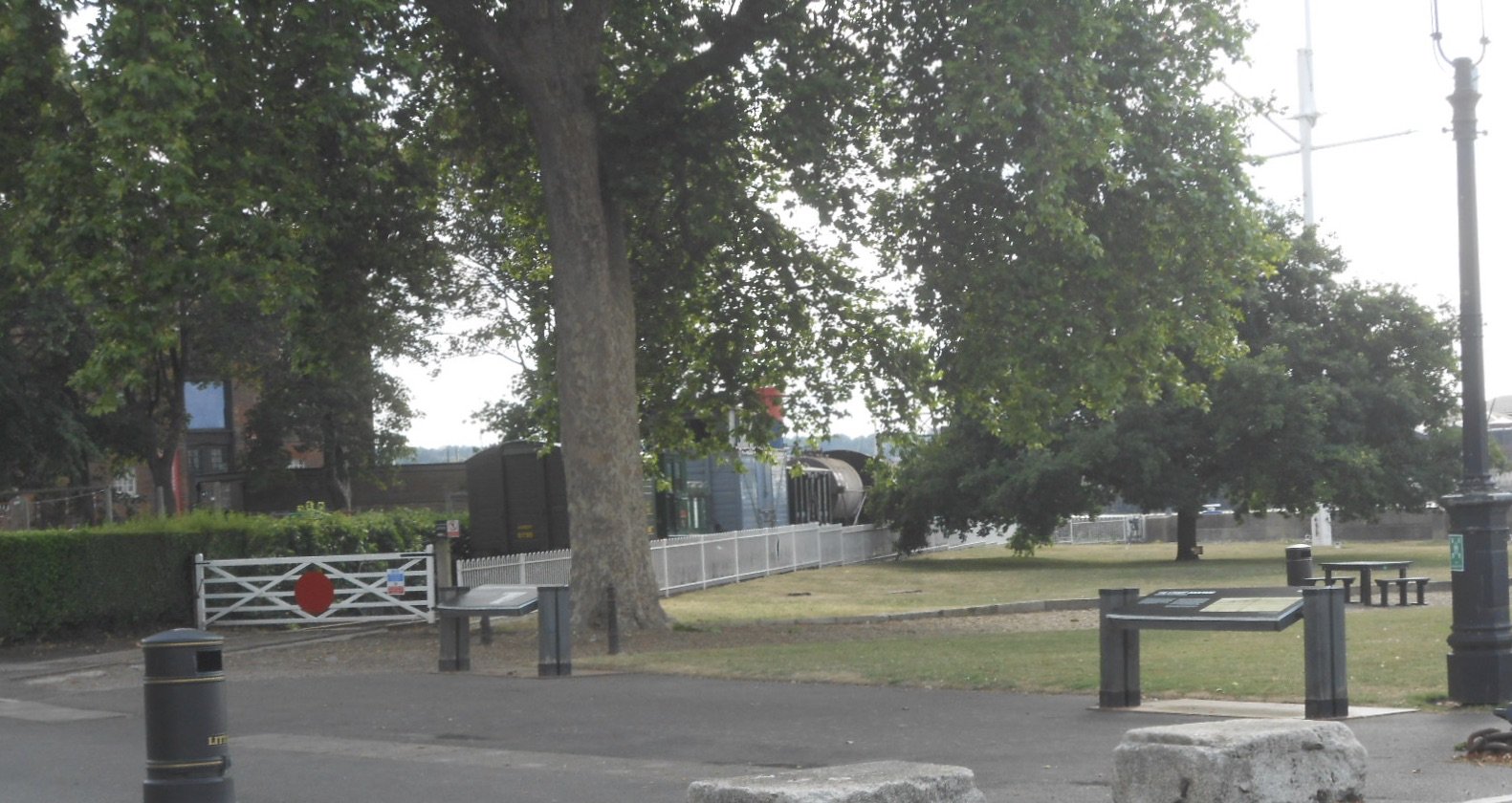
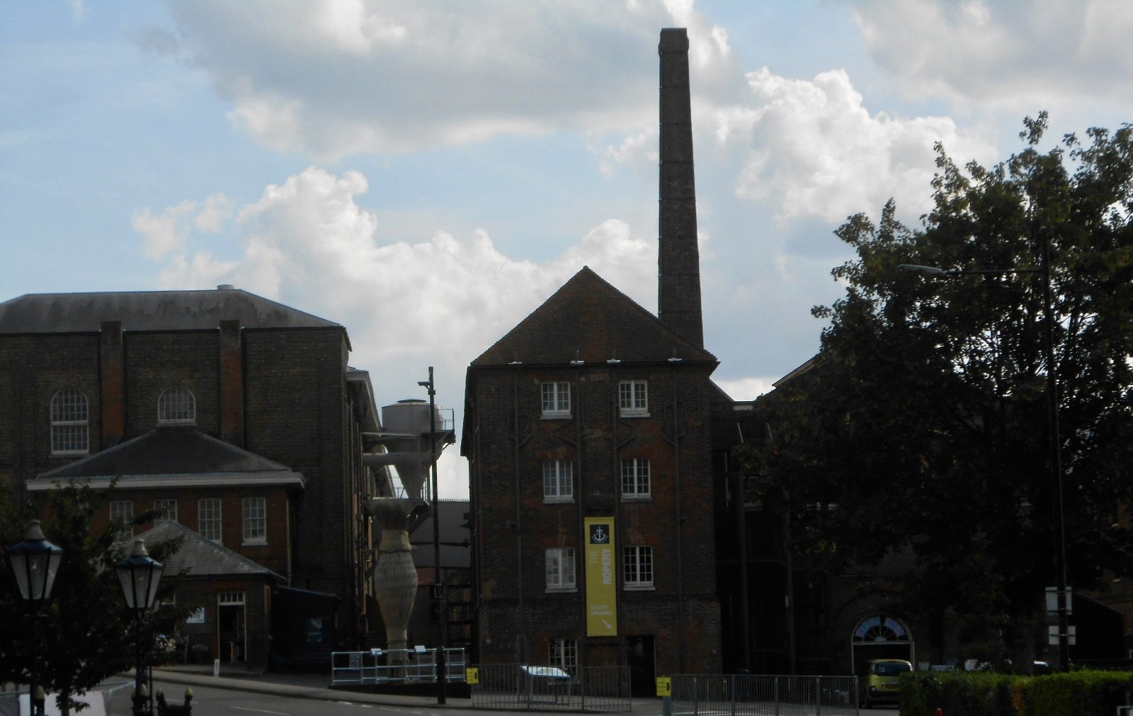
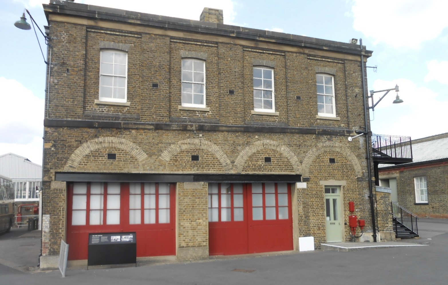
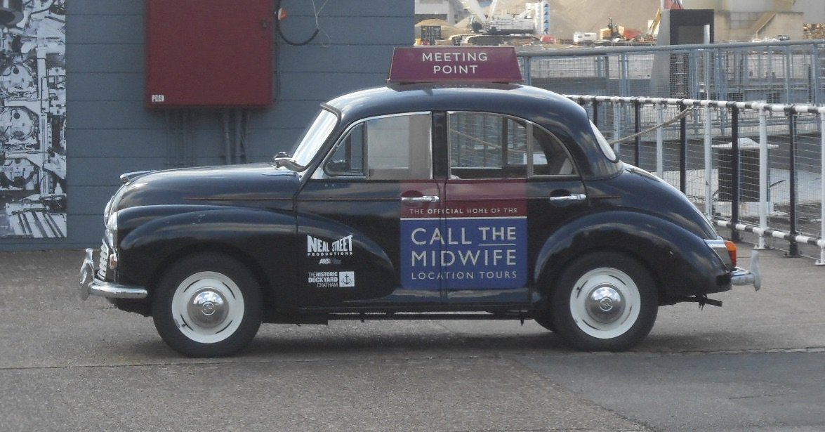
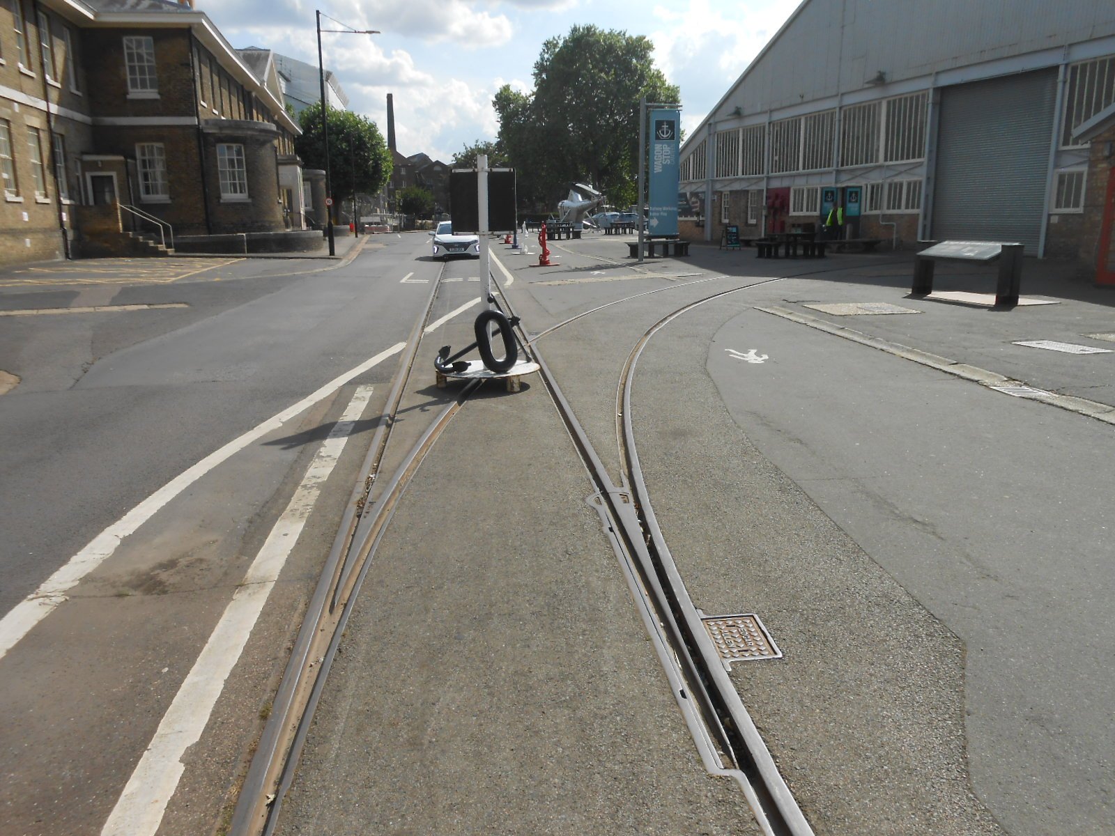
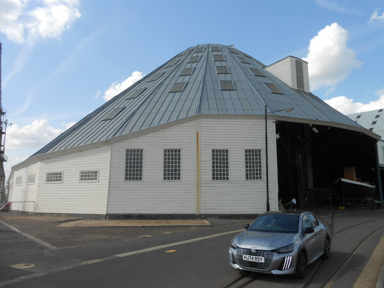
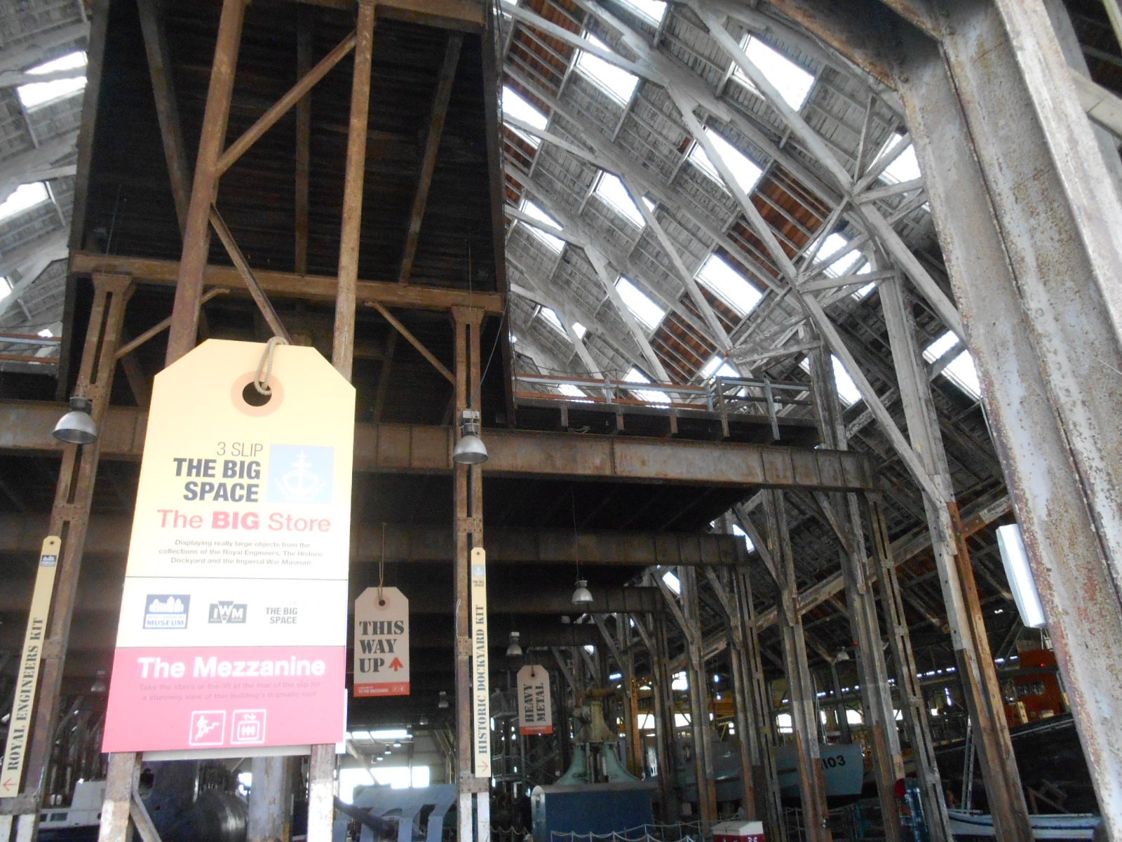
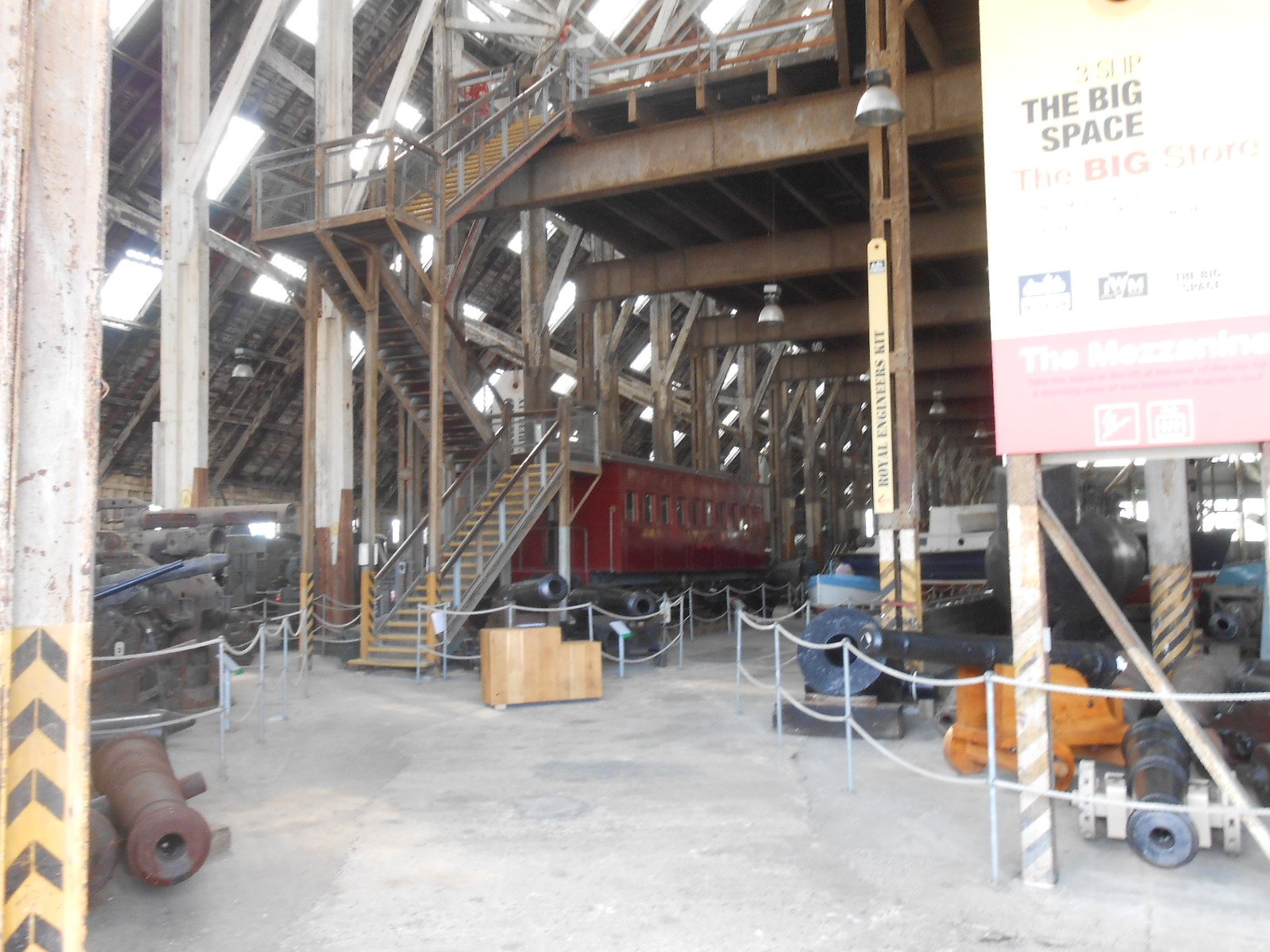
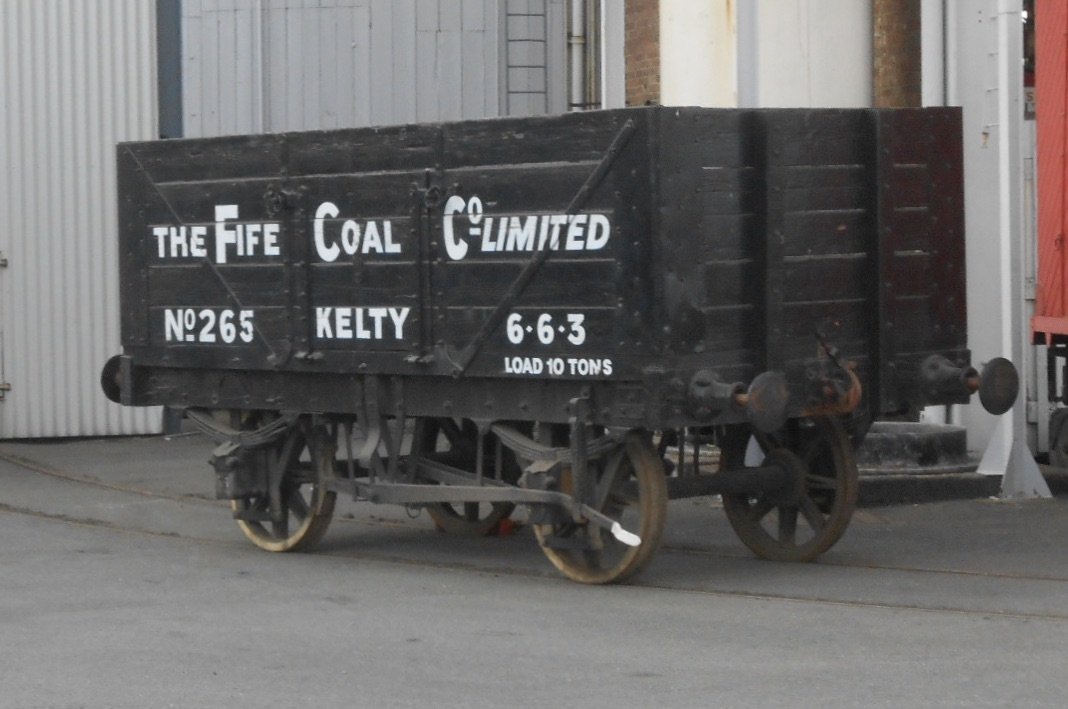
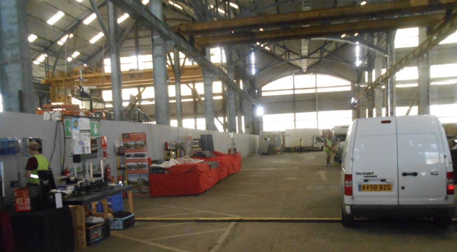
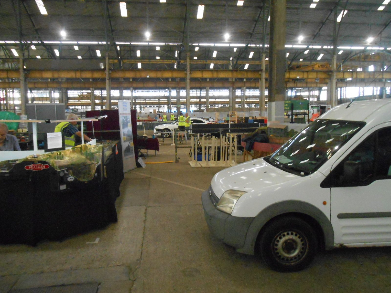
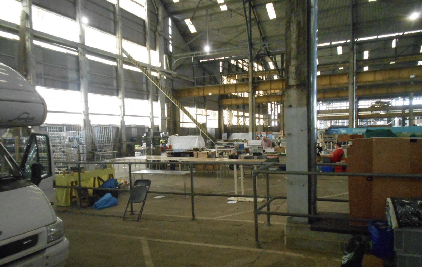
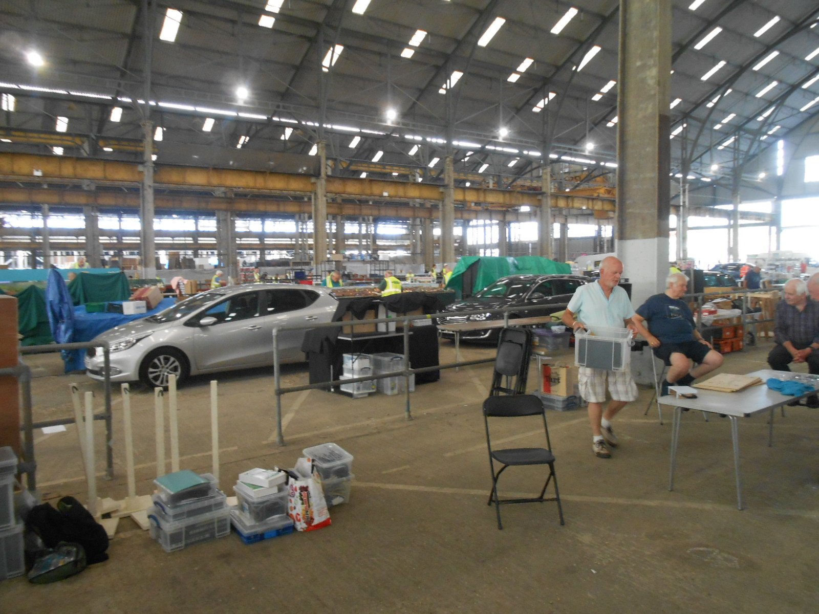
Thought I'd give an overview of our Exhibition, now back in the Historic Dockyard for a second year. The Chatham & District Model Railway Club has had premises here since about 1990, though it goes back to just after WW2. The Historic Dockyard Museum celebrates the history of the Dockyard, which includes, among other things, the building of sailing ships going back to Tudor times, not least HMS Victory, Nelson's flagship at Trafalger. More recently, iron and steel ships were built, including submarines. The site is huge, with many important buildings, which now house other national collections. Our Show takes place in the Number 5 Covered Slip, once used for shio building. but now a vast, barn like structure. A similar slip next door houses a lifeboat exhibition. Opposite is what is known as the 'pea shingle', a large square, where we once held a show in a marquee. The was the year Adavoyle visited & was lucky to escape when the roof leaked! Note the range of historic buildings in the background. Next come three open docks. The first holds HMS Gannet, a Victorian 'iron clad', while the second is home to HMS Ocelot, a post WW2 attack submarine. Finally comes the destroyer HMS Gannet, built at the end of WW2 and, at the time, one of the fastest ships in the Fleet. All three are open to visitors. More fine buildings lead you past the helipad, next to which is a loco shed. Inside the loco shed at the moment are an early diesel shunter and Marcia, which is owned by Andrew Hardy, proprietor of Rapido Models. Marcia has only recently moved here, but is used regularly, including this weekend, offering 'Driver for a Tenner' runs. All proceeds go to the Dockyard. The almost rural scene below is where a number of preserved wagons are stored, along with a couple of working steam steam cranes too. After that comes Anchor Wharf and the Ropery, a run of Georgian buildings over 500 metres long. The Ropery still makes specialist ropes, while the space between the two buildings is regularly used for filming scenes for the 'Call the Midwife' TV series. Indeed many feature films have had sequences shot here. The Model club has premises in a 16 metre square cellar here too. Among other buildings is the old fire station, while the tramway tracks wander all over the site, some of which are still in use for public displays. Indeed, some of our club members are qualified steam and diesel loco drivers for the Dockyard. Heading back to the exhibition hall, we pass the original No1 Covered Slip - a fabulous timber framed building, home to a mezzanine exhibition space and an eclectic collection of dockyard stuff below. Back outside our exhibition hall is this Fife Coal wagon, which the club are helping to sponsor its repairs. 4mm scale models have been commissioned are are on sale at the show. Inside the hall here are are a few pictures showing exhibitors setting up this afternoon. Layouts include James Street [N gauge in this month's Modeller] and a 20 metre long Gauge 3 [1:22]. Around 40 layouts in all and a total of over 100 stands. Entry to the show gets you a half price ticket to the rest of the Dockyard and if you can't make it this year, plans are already well advanced for 2026. Will post more pictures from the show itself tomorrow and Sunday.
- 10 replies
-
- 11
-
-
-
Good on you Patrick. Feel sure you will enjoy working in 7mm scale and 0n16.5 is a great way of doing it because the track is indeed easy to work with, while your obvious talents with buildings and scenery should likewise embrace the larger scale. Very addictive though - but I would say that!
-
Great project and a worthy accompaniment to a Queen.
-
Beagnach end: A Branchline terminus.
David Holman replied to Metrovik's topic in Irish Model Layouts
Small as you like! Nice excuse for a bit of creativity to show off (and enhance) a favourite model. -
British and Irish on top in Tour de France!!!!
David Holman replied to leslie10646's topic in General Chat
And the Lions play the first test in Australia on Saturday. Always good to play the Aussies. Even better if we can beat them. -
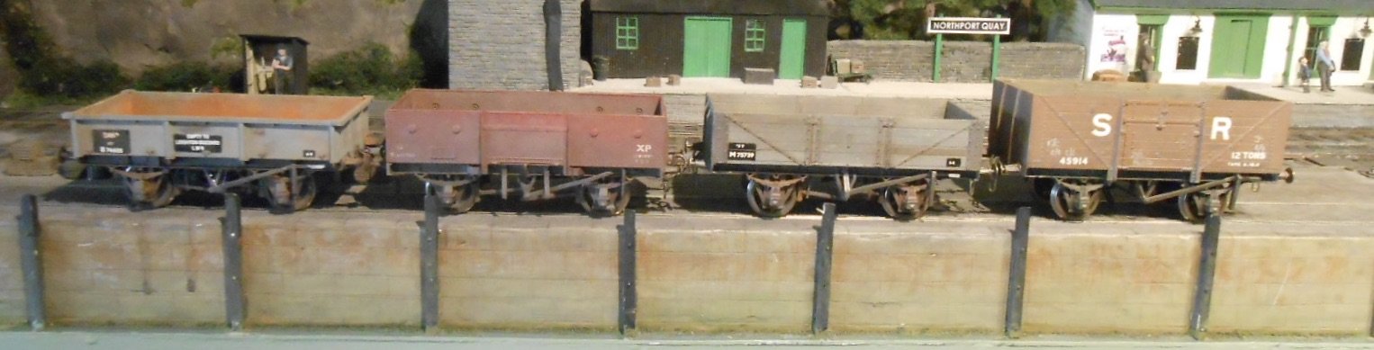
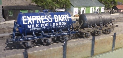
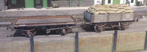
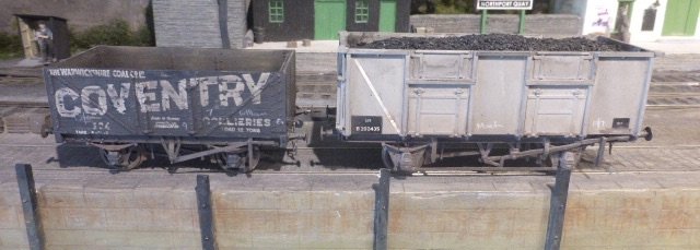
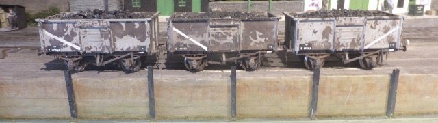
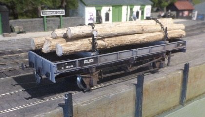
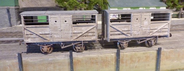
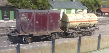
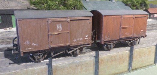
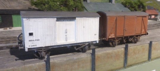
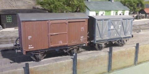
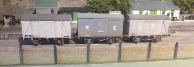
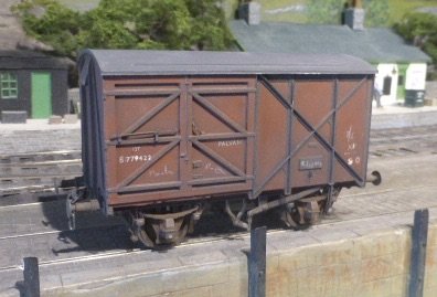
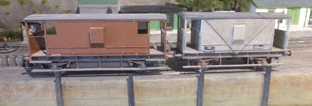
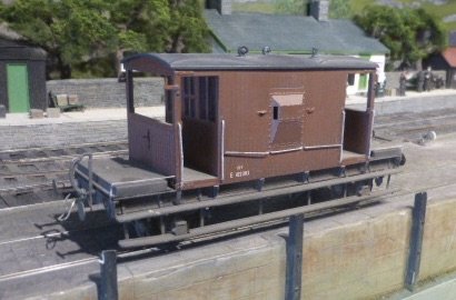
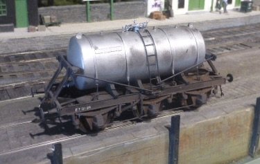
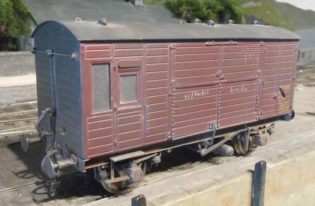
Freight Stock Pretty much everything is either from kits by Slater's or Parkside. Apart from paint, both types come complete, including transfers and and generally easy to build, even for a beginner. I was very much making them when Martin Welch was sharing his weathering techniques in Model Railway Journal. His seminal 'Art of Weathering' appeared at the same time & even nearly 30 years later, remains my go to book on the subject. First up, a mix of open wagons that formed the basis of an unfitted goods train. My J15 was used for this, as I deliberately made it a steam brake only loco, meaning the buffer beams were completely uncluttered with hoses and just had three link couplings - ideal for working by the Great Hand From The Sky. A method I still like, by the way, but it is not ideal when operating from the front at exhibitions. No 1950s layout is complete without a few steel minerals. Very much followed Martyn Welch's teachings for these. You paint the rust colour on first, then [when dry] cover it with Maskol. Once this has gone off, paint the top coat [wagon grey]. When this is dry, take a fine pair of tweezers and pick off the Maskol, hence leaving the rusty patches underneath the top coat, often with some nice peeling edges too. Now some specialist vehicles in the form of cattle wagons, a container flat and a petrol tank. More about the tanker later. I built a fair selection of vans over the years. The unfitted ones usually went with the J15 and pick up goods, while the fitted vans made a train of their own. That said, the fish and meat vans above, usually got included in the 'stock train' mentioned in the previous post. There are three brake vans, essentially LNER based, though the one above also became a BR Standard. Finally, the milk tankers. Three Slater's six wheelers, these are certainly not for a beginner or the faint hearted. Probably one of the most complex wagon kits available. Part of the reason for this is that everything in the under frame is on show, plus there are lots of fine details. These are real mixed media kits involving plastic mouldings, etched brass, lost wax brass castings, wire and other fittings. The build is further complicated by the way the tank is arranged. You'd think it would be a tube with cast/moulded ends, but no - the tank comes in three sections, split 120 degrees longitudinally. There's some lovely fine moulding, but when sanding those joins flush, you have to be really careful not to scrub it off. I think there is about 50 hours work to finish one of these tanks, which makes the recent ready to run versions an absolute bargain. Hopefully, I'll be able to post pictures of this stuff, in action on the Club layout after this week's Chatham Show. Thursday is moving day - breaking the layout down and transferring it all to the the venue in the No5 Covered Slip. Friday will be getting everything running, with last minute fettling, while on Sunday evening it all has to go back to our Clubroom in a cellar under the Ropery. Wish us luck!
- 90 replies
-
- 11
-
-
Very dainty and full of those all important details, whatever they are! Signal boxes are a bit like coaches - should be just a simple glazed box, but there is a lot more to them than that.
-
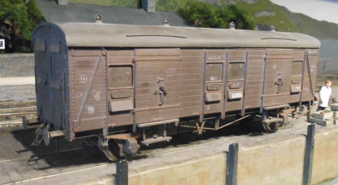
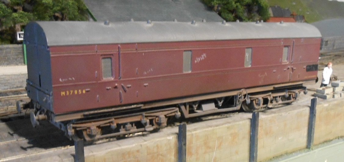
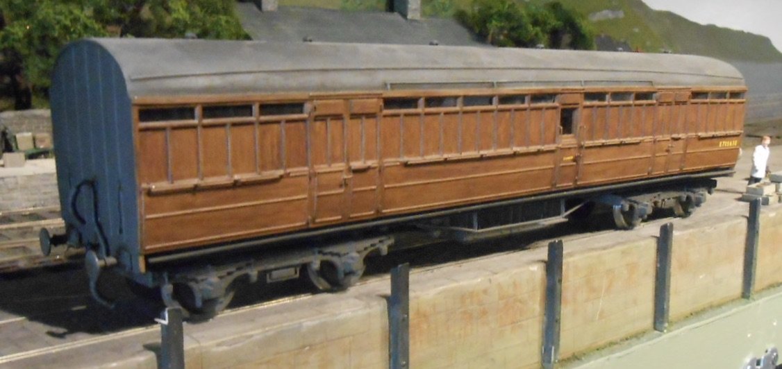
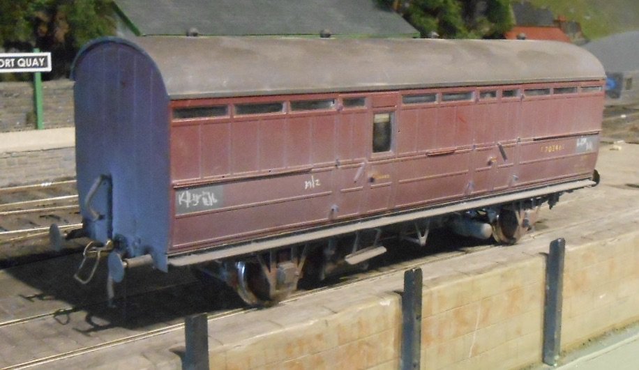
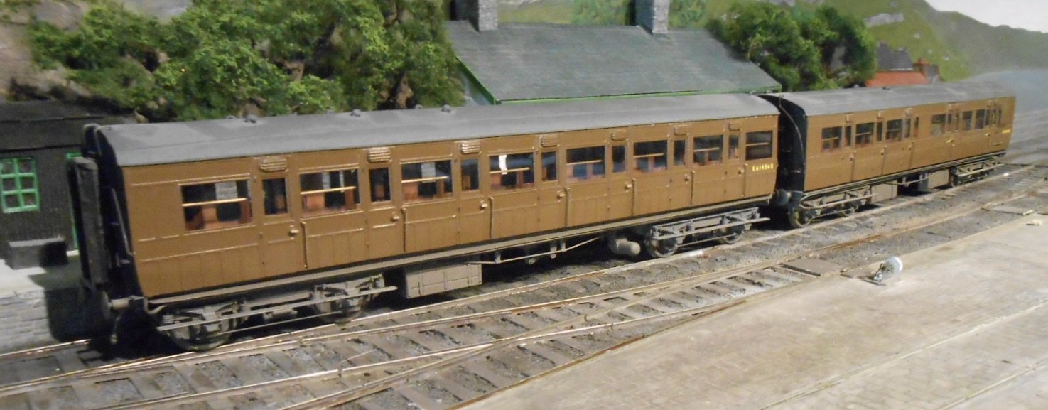
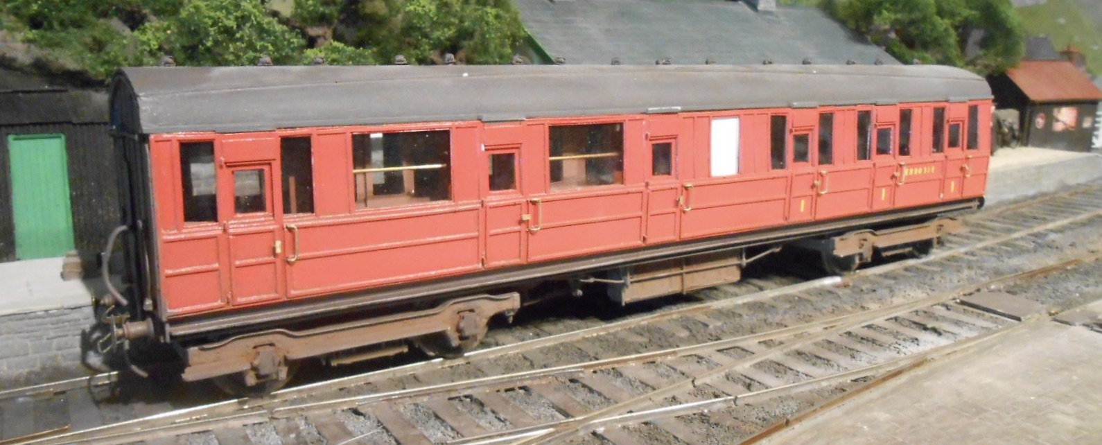
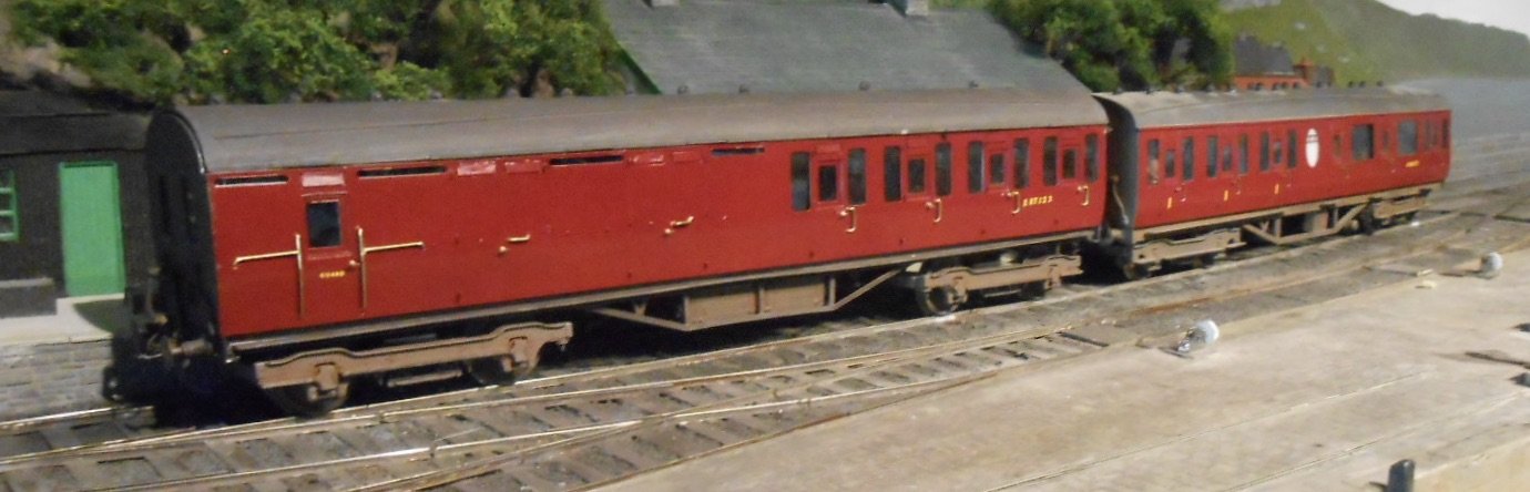
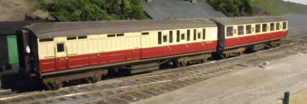
Parcels Stock I've always had a thing for parcels stock - it is probably down to the variety that could be seen in a single train, so I built up a decent sized rake, along with the option of adding a parcels van to a short passenger train, which I also like. First up is a Southern Railway GUV. These seemed to turn up all over the country for parcels and newspaper traffic. Mine is the Slater's kit & very nice it was too to build. Next we have an LMS bogie GUV. Another nice vehicle with its short bogie wheel base. Unlike the Slater's kit [mostly plastic], this one, from Wagon & Carriage Works is mostly etched brass and white metal castings, so it rather heavy. The LNER full brake is much lighter, being an Ian Kirk plastic kit. Fairly basic [and therefore requiring a bit more work to be presentable], these kits were nevertheless very cheap and good value. Getting the roofs to sit properly could be a pain though. The LNER pigeon van was either D&S or W&C again, hence mainly etched brass and white metal. Back in the day, racing pigeon traffic could be quite substantial. Below that is an LNER horse box, from one or the other of those stables [pun intended]. So, a nice mix of shapes, sizes and roof lines, which when added to vehicles like fitted vans, milk tanks and the like, makes a classic Eastern Region 'Stock Train', which I'm hoping to run next weekend at the Chatham Show, behind either my B17 or D16. Coaches Quite an eclectic mix, mainly because passengers trains on Eatonswell only ran to three coaches, or two and a parcels van. First up is a pair of ex Great Eastern corridors. They were D&S kits bought not just because I liked them, but also because MRJ ran a couple of articles on how to build and detail them. On Eatonswell, they usually ran with the SR GUV behind my E4 2-4-0. A trio of Gresley 'short' bogies next. The composite was scratch built in plastic card and strip on Wayoh bogies, while the pair in 'blood & custard' are Kirk kits. The B17 used to work these - a bit of a down turn from previous express duties, but it was often the case of them being relegated to local trains once the B1s and Britannias arrived on the scene Finally, a couple of Thompson suburbans. The brake 3rd is scratch built [Wayoh bogies again], while the composite is another W&C kit. They often ran with a horse box, hauled by the F5 2-4-2T.
- 90 replies
-
- 10
-
-
-
Fabulous. Well done Paul. For me, there has always been something special about S scale, be it the imperial nature of it all to that almost ideal intermediate size between 0 and 00. Teamwork looks great and I've always loved the idea of the 63/64th" track gauge.