Tullygrainey
-
Posts
958 -
Joined
-
Last visited
-
Days Won
56
Content Type
Profiles
Forums
Events
Gallery
Everything posted by Tullygrainey
-
Yes David, nice crisp etches which seem to go together well. Like many kits of the era though, the instructions tend to assume a certain amount of prior knowledge and can be a bit vague in places. I suspect a novice builder would be pretty flummoxed. As an example, there are half etched cutouts for hornblock mounting but no reference to these in the instructions which describe building a fixed chassis. The builder of a compensated chassis is assumed to know how to do it I suppose. There's no guidance on, or provision of etches for, compensation beams.
-
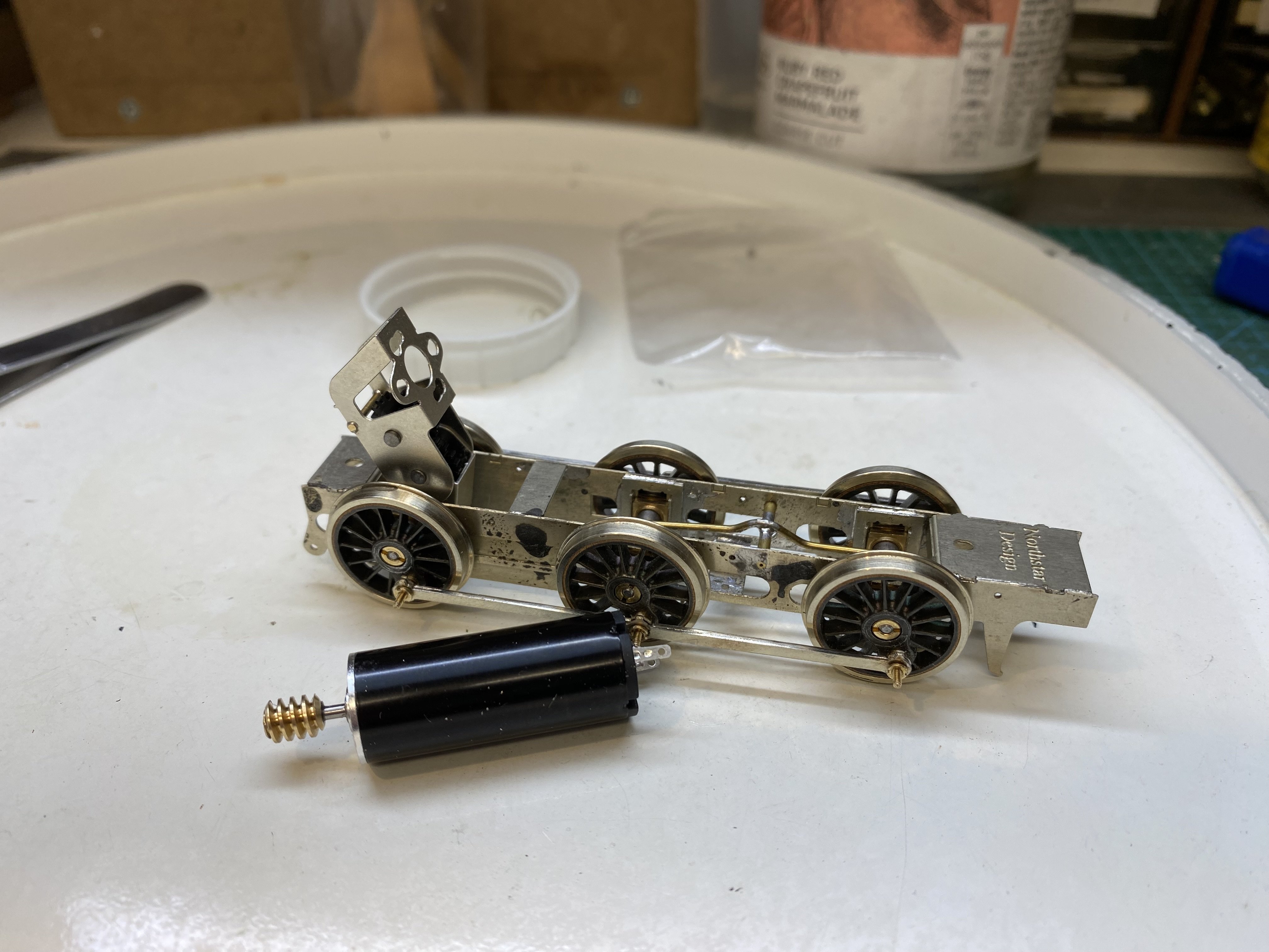
Another High Level gearbox takes shape - a RoadRunner Plus this time. This one is destined for a GNR(I) AL Class 0-6-0 locomotive which Kieran Lagan is building in 4mm from a NorthStar kit acquired at the Bangor Show. IMG_3655.MOV

-
Coming along nicely Patrick
-
Innovation and improvisation. Name of the game. And if it works, it ain’t wrong.
-

Beagnach end: A Branchline terminus.
Tullygrainey replied to Metrovik's topic in Irish Model Layouts
Makes it seem like you’re standing lineside. -
Always tricky going round corners. That arrangement works well.
-
Beagnach end: A Branchline terminus.
Tullygrainey replied to Metrovik's topic in Irish Model Layouts
All the best for the exhibition John -
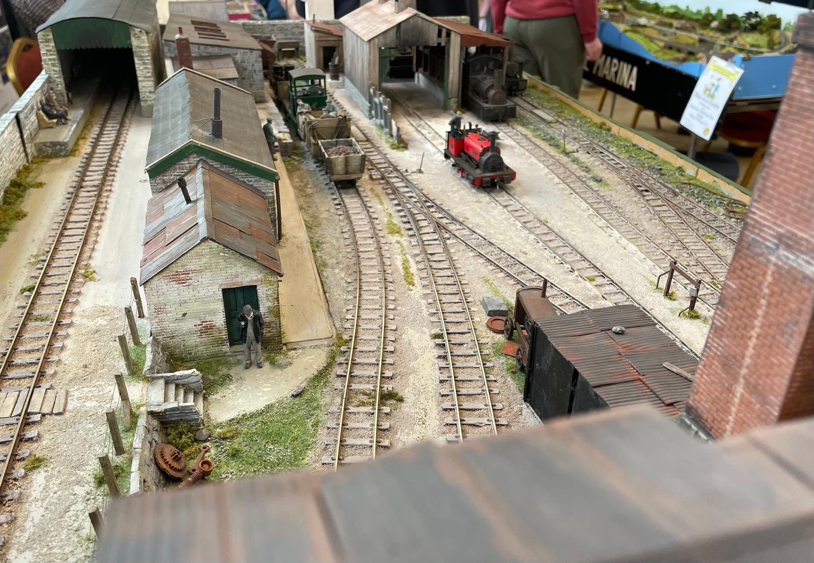
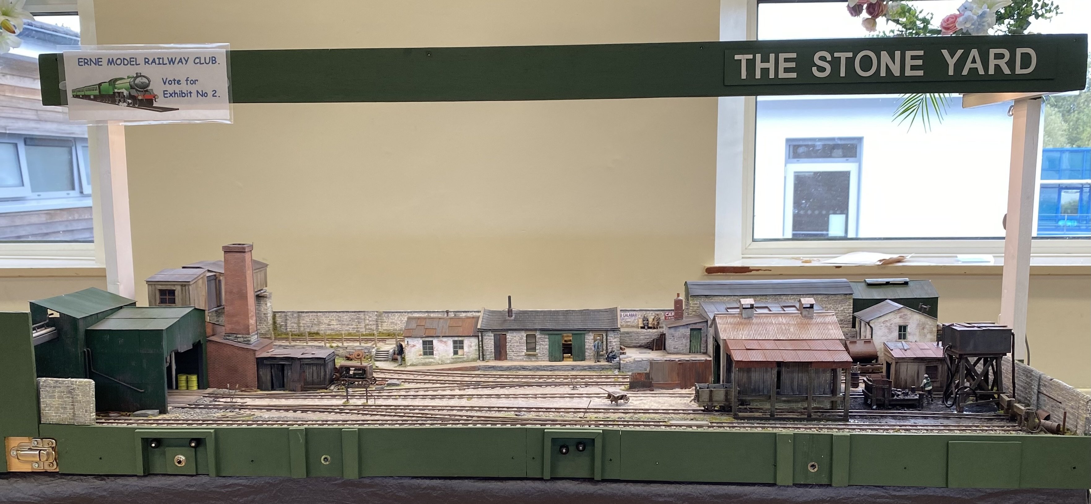
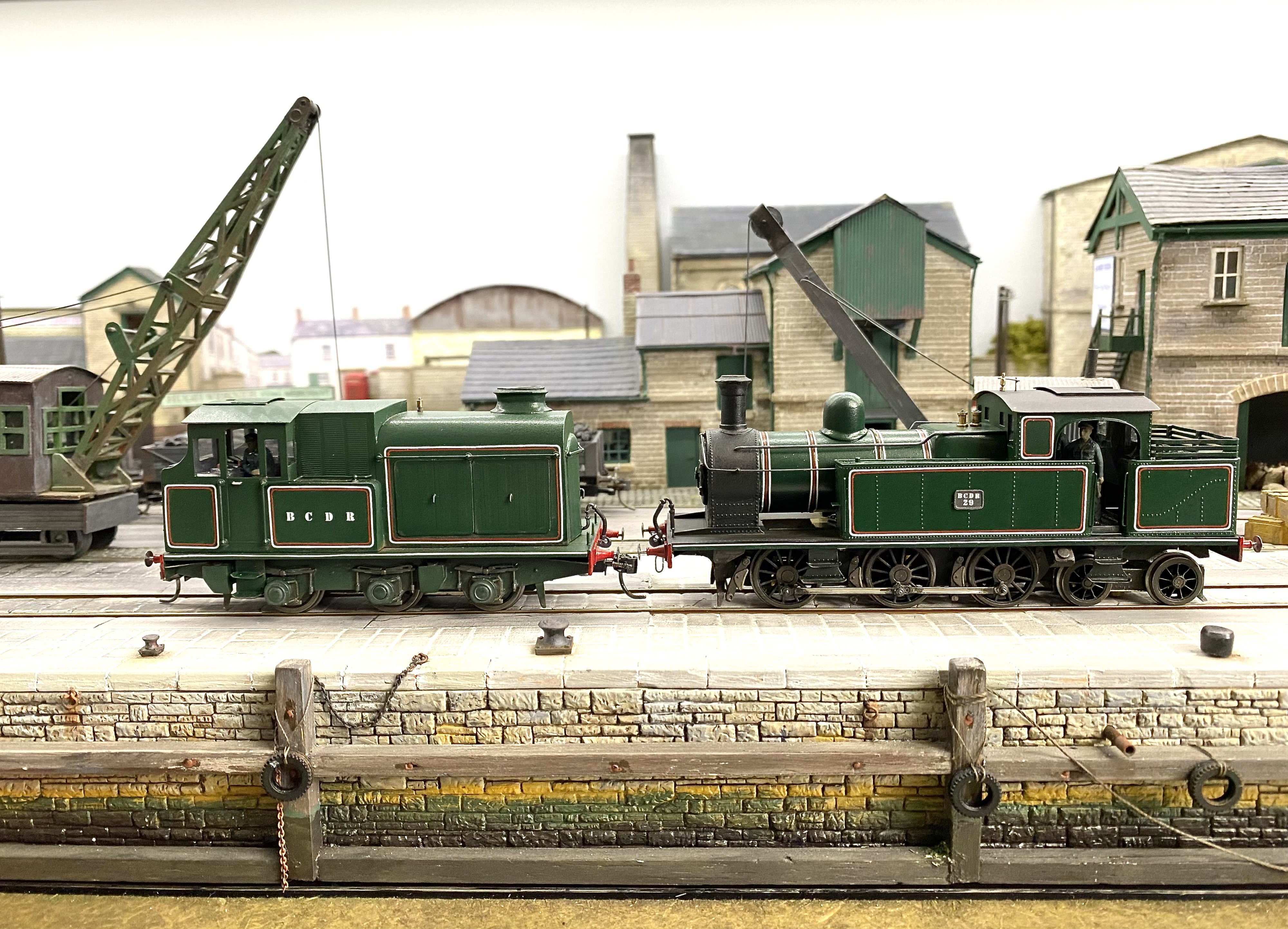
The Stone Yard had an outing to the Erne Model Railway Club's annual exhibition in Enniskillen on 20 September. Many thanks to the EMRC for an enjoyable show and to Kieran Lagan as always for help and for this photo. An angle not often seen.
- 113 replies
-
- 11
-

-
Actually it’s a flight of fancy
-
Maybe, but I think we may be looking at the rear of the train. I don't see a driver and the destination board seems to say Central.
-
-
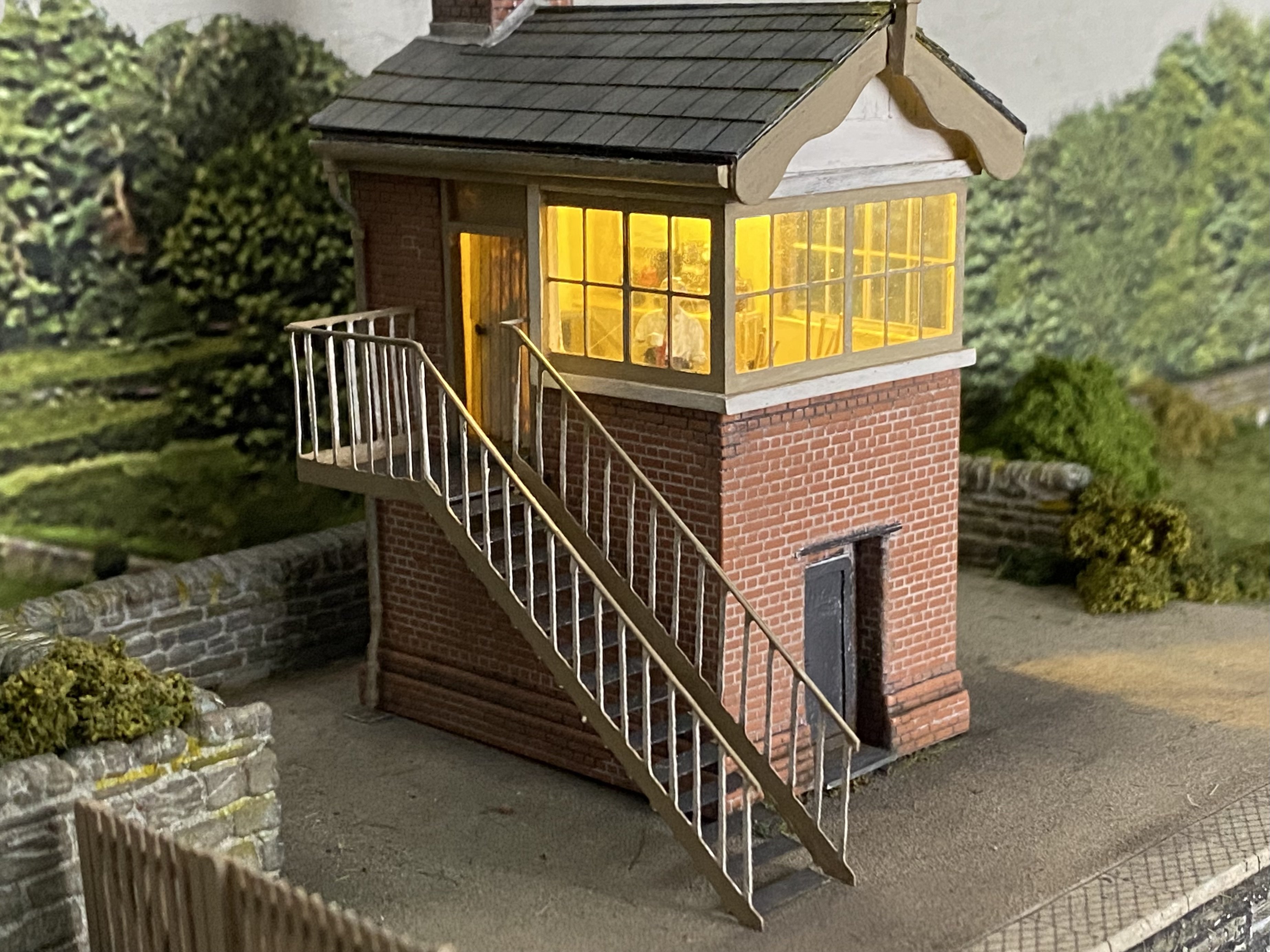
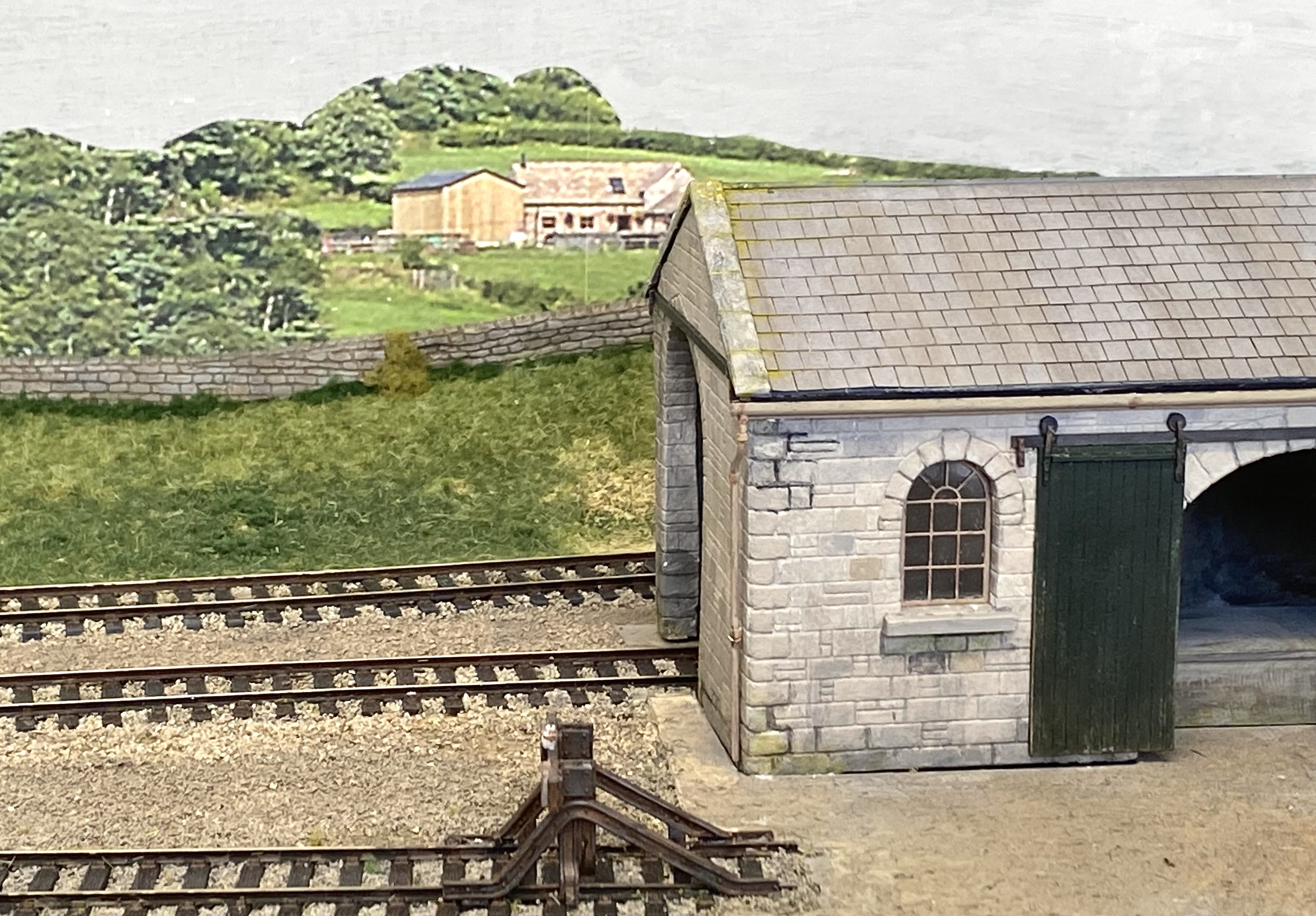
Let there be light. Someone appears to have nicked the lead flashing from that roof. That needs seeing to.
- 121 replies
-
- 15
-

-
-
Brookhall Mill - A GNR(I) Micro Layout
Tullygrainey replied to Patrick Davey's topic in Irish Model Layouts
Did you warn the new owner about Mr Weaver Patrick? Or has he really retired? I'm sure I can already hear him issuing orders. -
Stanley Unwin! Brilliant. He was a one-off. The only man able to talk completely comprehensible gibberish.
-
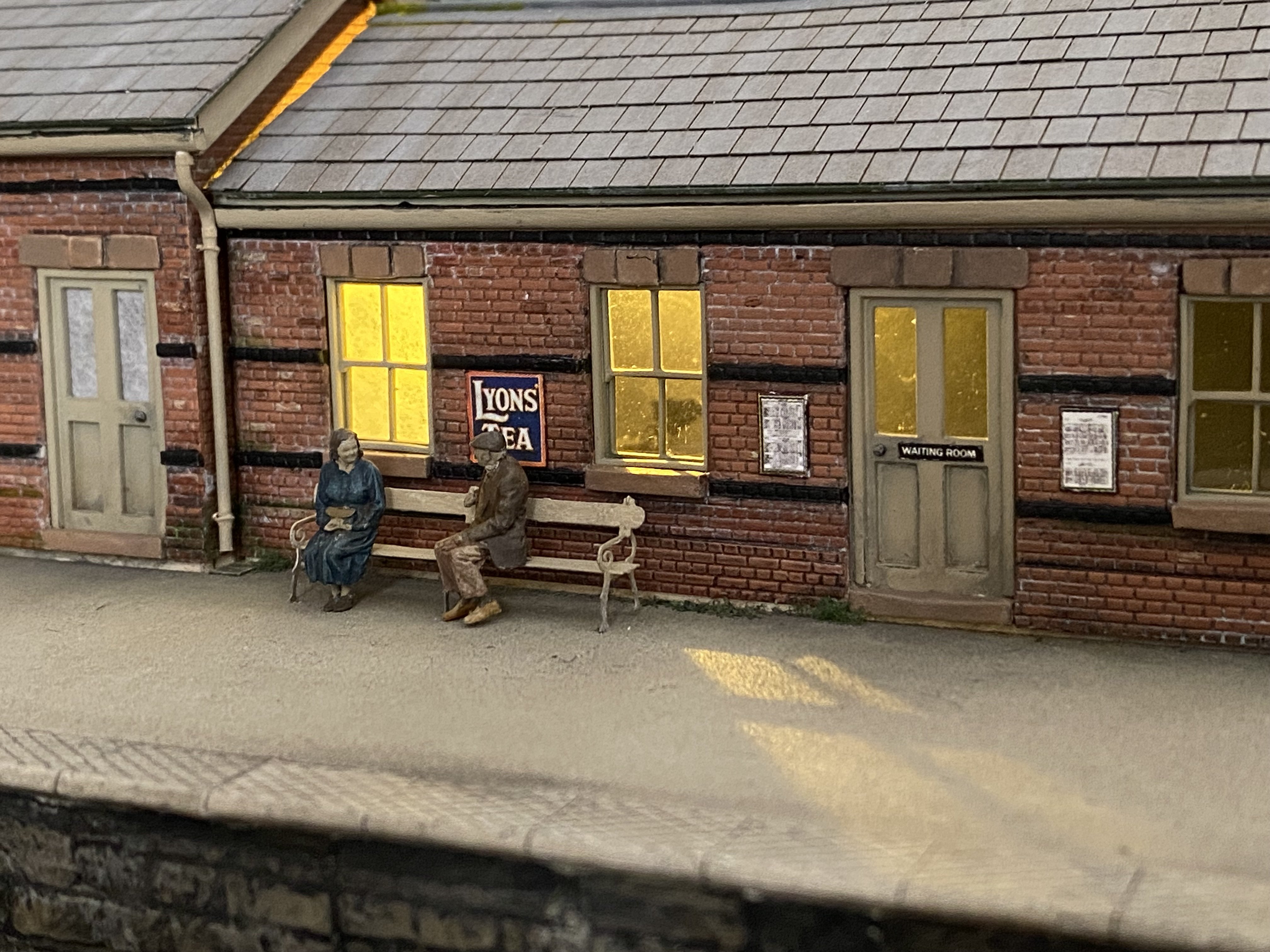
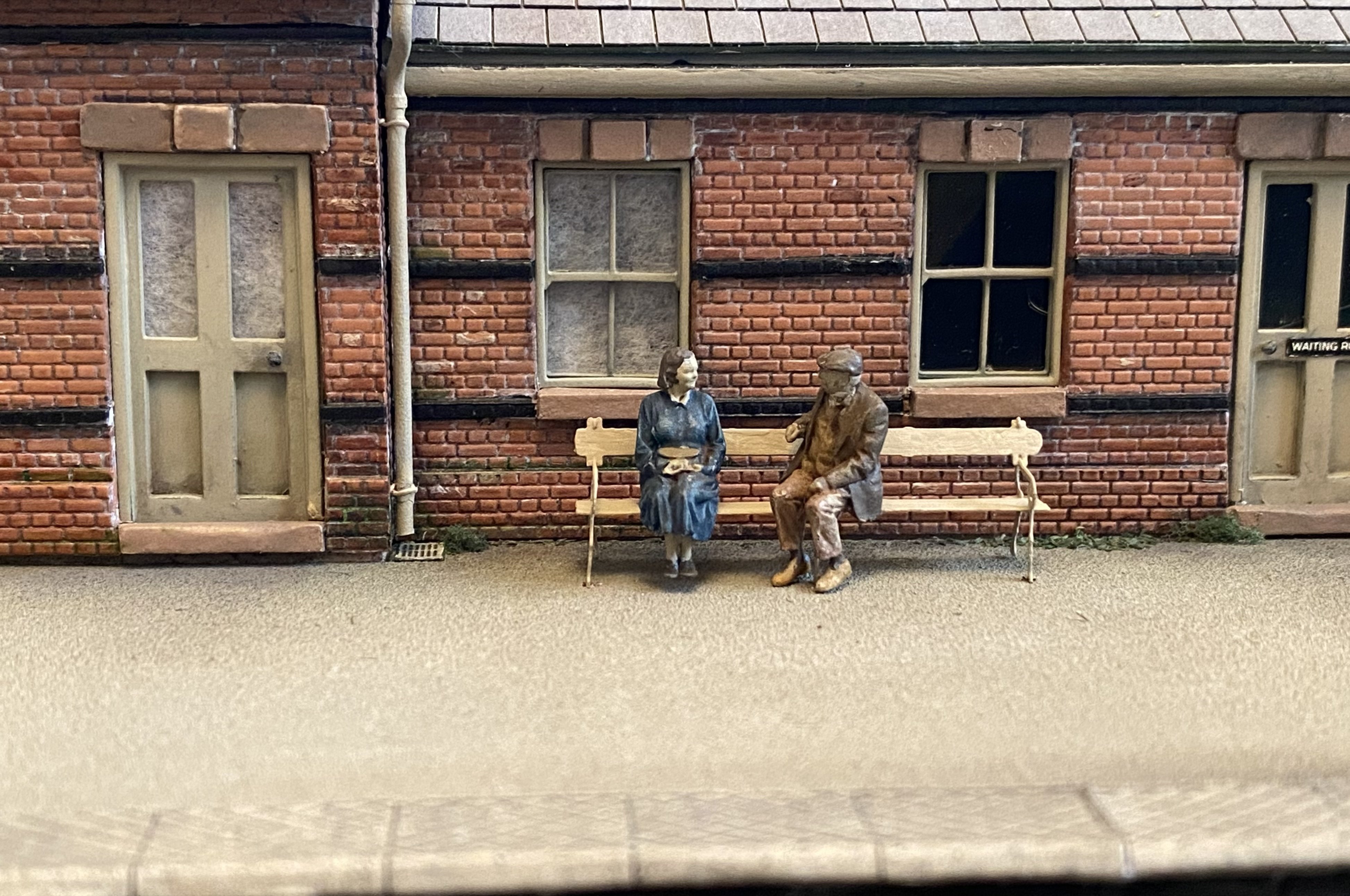
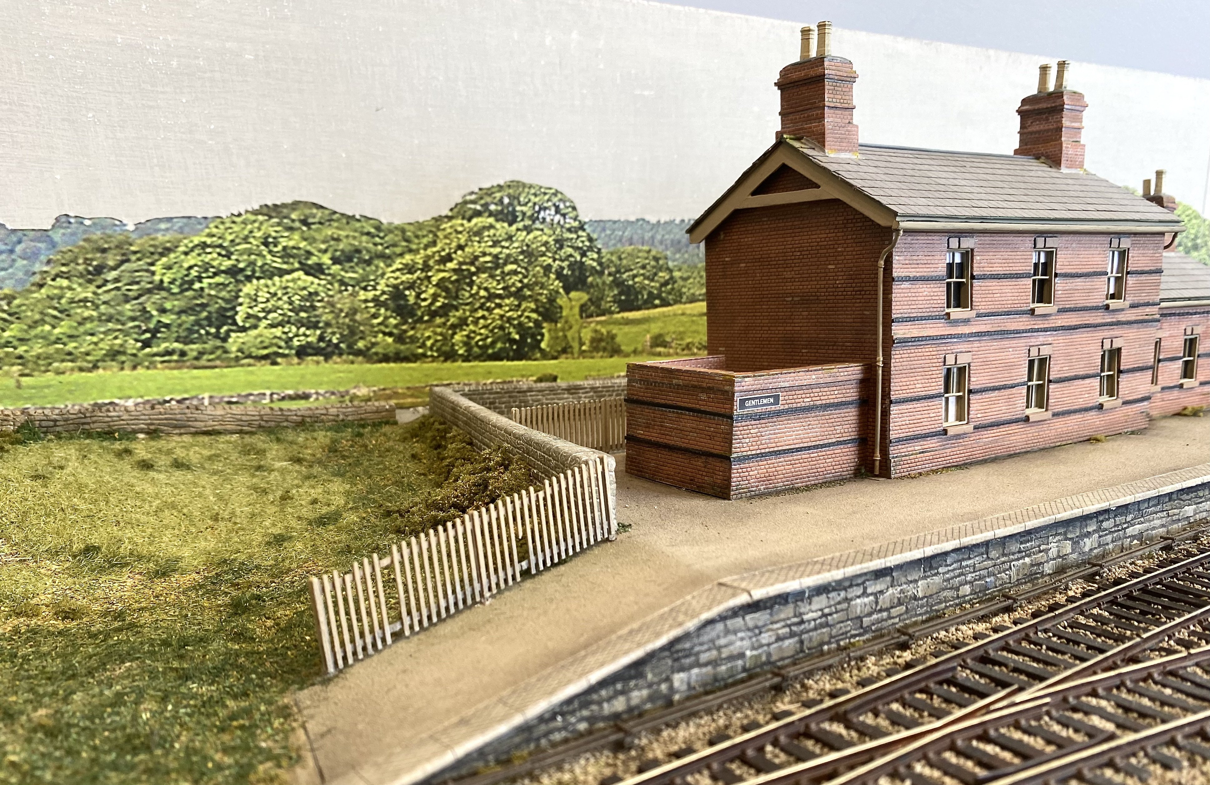
Mr and Mrs McQuillan who patiently waited for the 7mm narrow gauge train at The Stone Yard recently decided to move house and now they wait for a different train on the platform at Kilmore. Yes..., they've downsized. I'll get my coat.
- 121 replies
-
- 16
-
-

-
-
Lovely work Patrick. Totally convincing
-
Thanks everyone. A real team effort, this one.
-
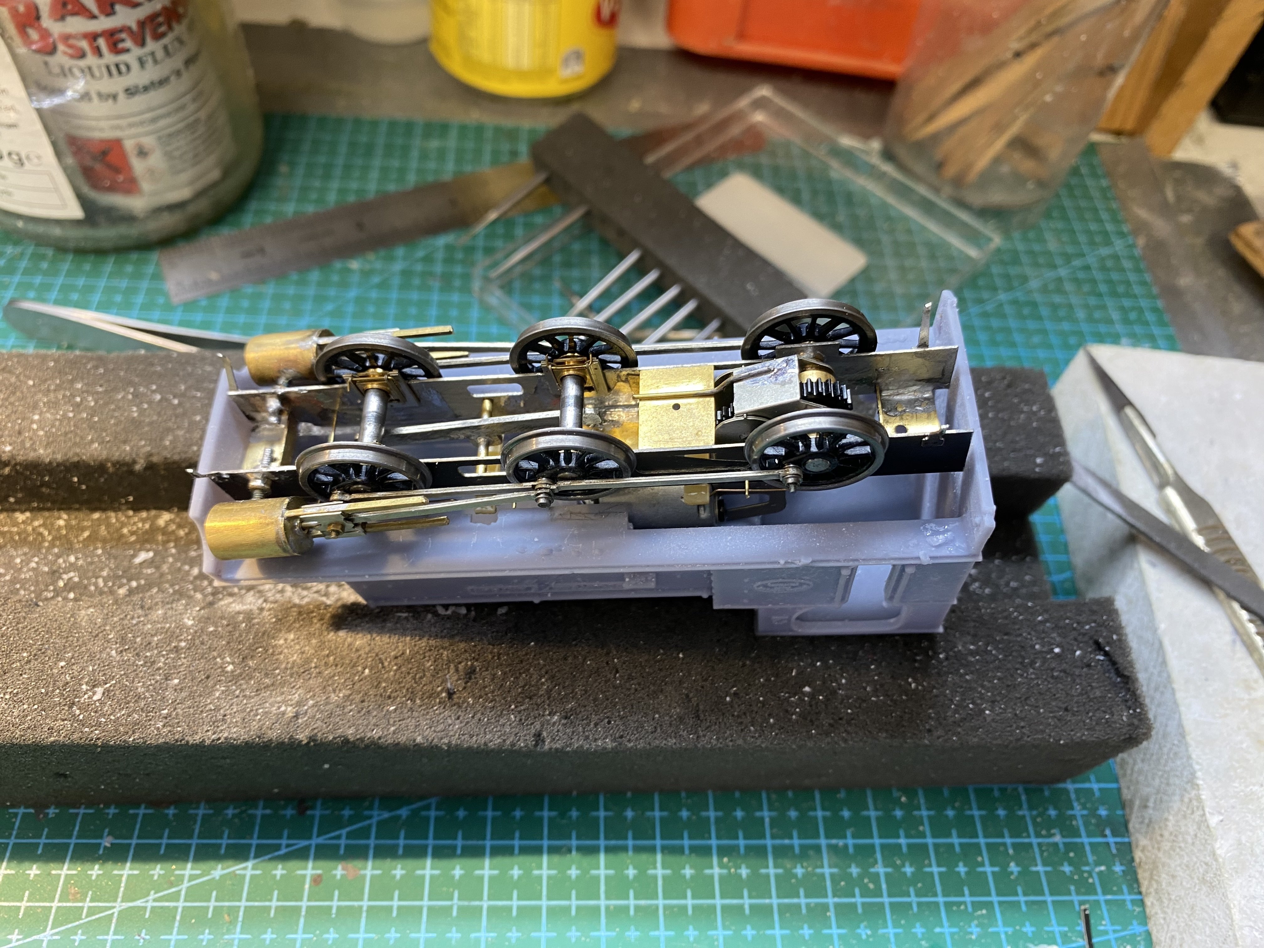
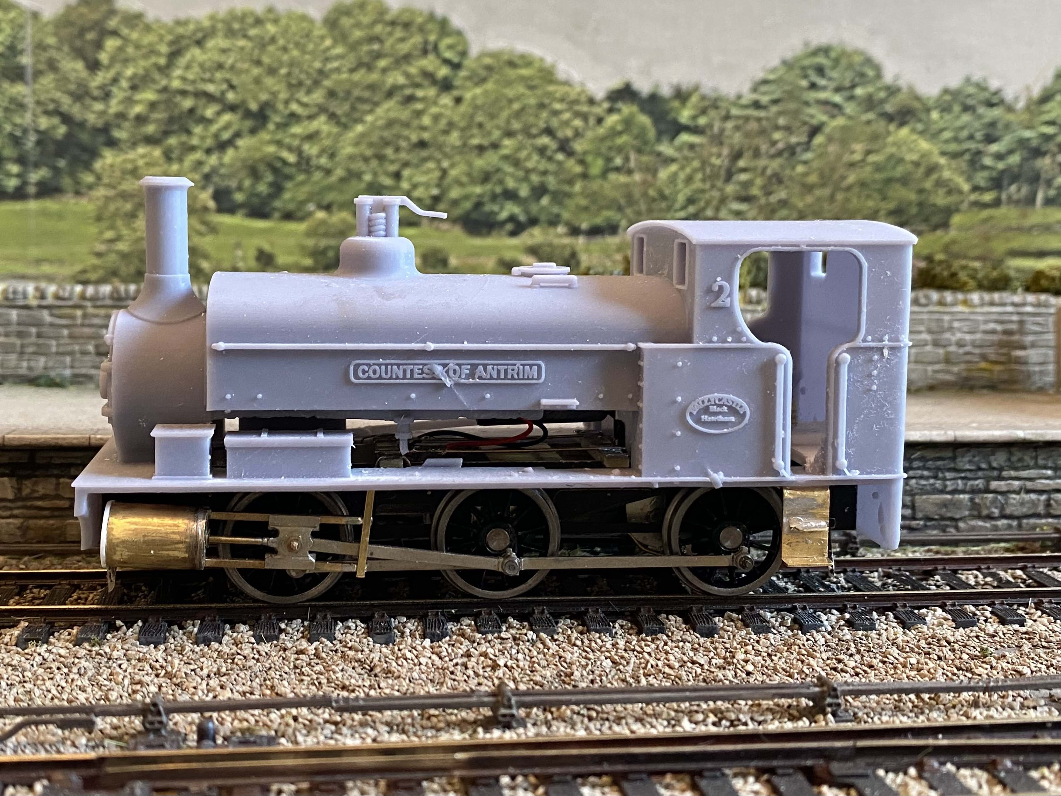
A change of direction with the Countess of Antrim project. The original plan was for Patrick @Patrick Davey to build a body in plasticard on my chassis. However he managed to source a 3D printed body, printed in resin by a friend from a file created and generously donated by @J-Mo Arts of this parish. And very nice it is too. As a result, the brass running plate is now redundant since the 3D print incorporates one and it would be highly problematic to try to remove it. Both body and chassis needed a bit of fettling (that's a technical term for "hacking lumps out of each") to make them get on with one another but we're just about there, I think. The Countess so far... Some cosmetic tidying up, detailing and then paint. Over to you Patrick
- 646 replies
-
- 18
-
-
-
-
That looks good David. Most unusual layout so well worth doing. I think modelling coaches requires high levels of determination and cussedness to see it through, so very well done. I've made a grand total of 3 in my time (in 4mm so fewer acres of metal and less need for detail) and it'll be a while before I have the stamina to tackle the three other kits nestling in the to-do drawer. I think it's the repetitiveness that gets me - multiple door handles, multiple grab handles, multiple ventilators, goodness knows how many window frames, etc etc. and every one a real fiddle. As David H said above, every bit as demanding as locos, just in a different way.
-
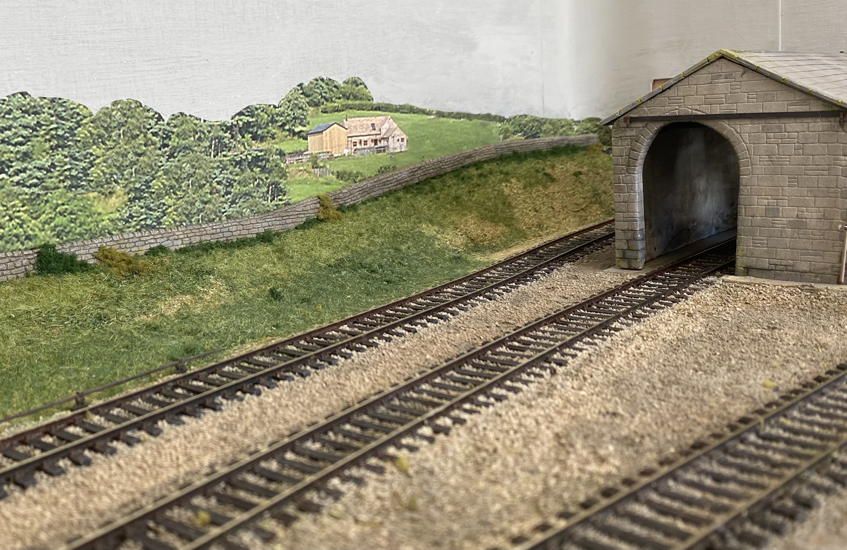
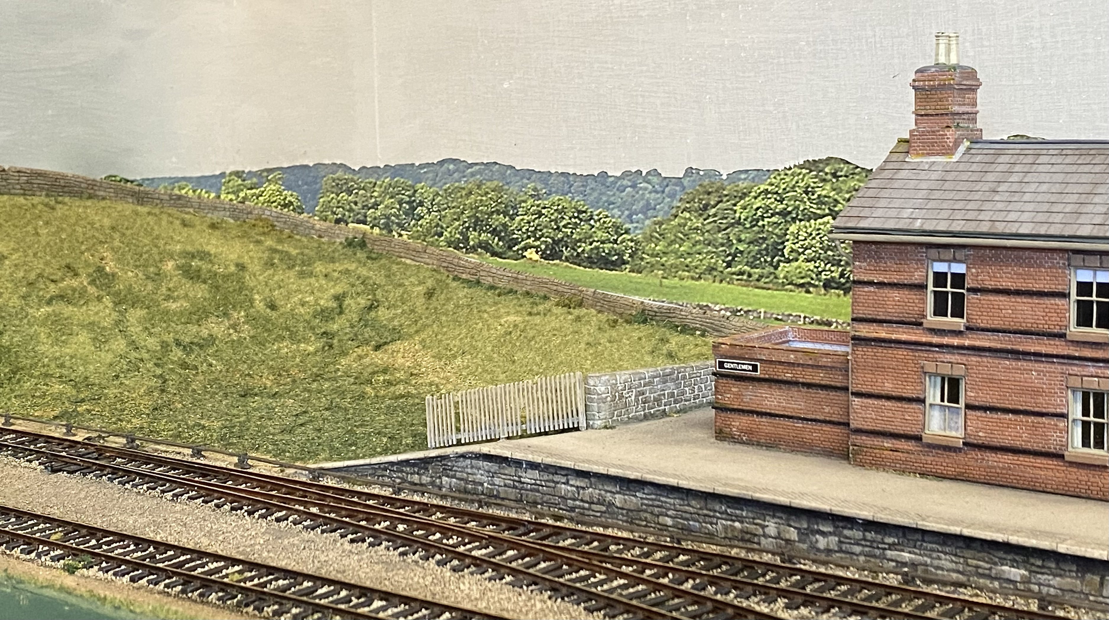
Yes, it's quite a good way to deal with that particular problem. A hedge would do the job too. I think it works best when there's a small gap between the physical barrier and the back scene board.
-
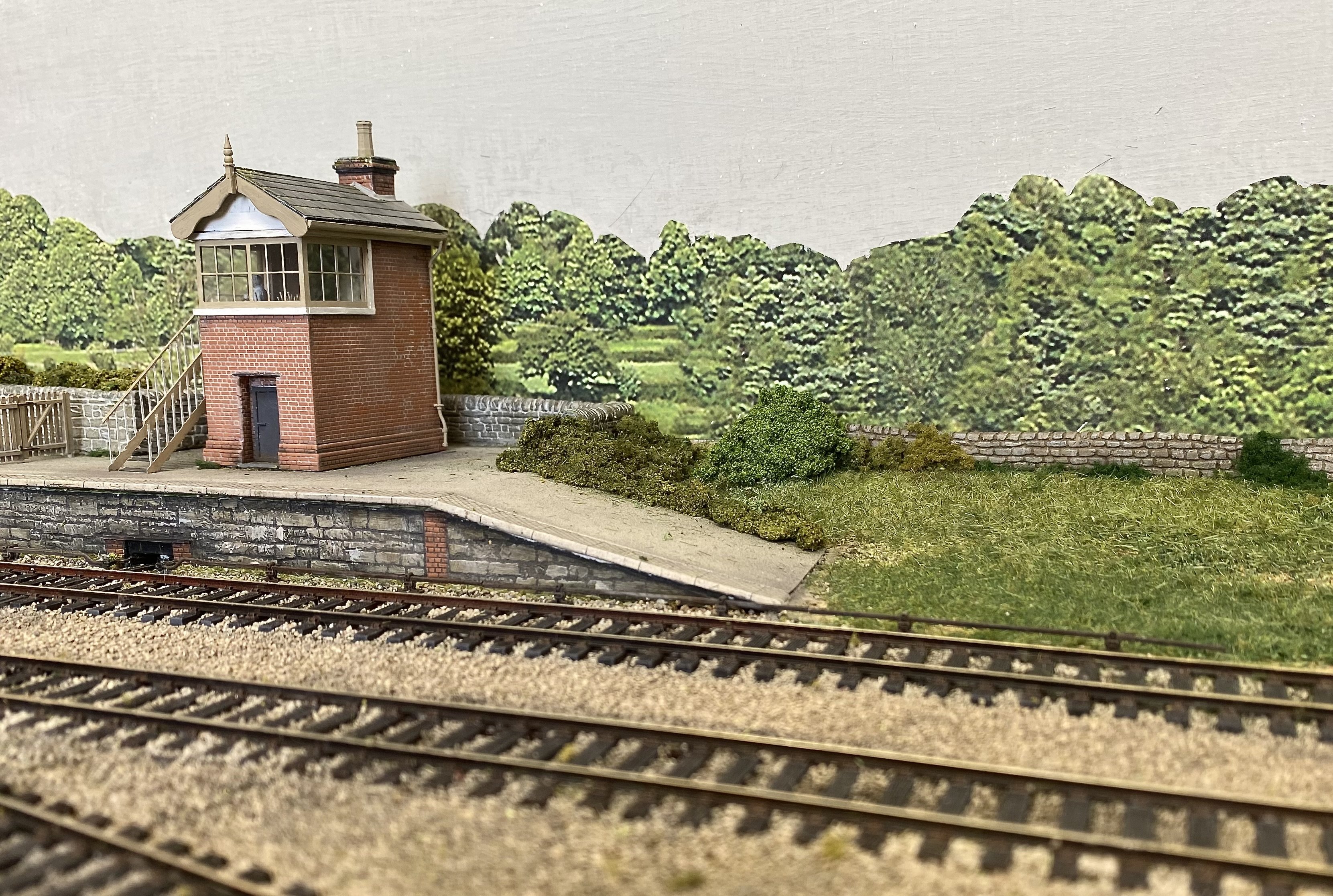
We've had some heavy rain this week after a prolonged dry spell. It's had an amazing effect on the countryside around Kilmore.
- 121 replies
-
- 23
-
-
-
Fine modelling of the derelict buildings. I do like a bit of rusty metal
-
A great start! This should be an enjoyable layout to operate. I like that cottage/farmhouse. The one with (Paddy Hopkirk's?) Monte Carlo mini parked outside. Scratchbuild? The cottage not the car
-
Clogherhead - A GNR(I) Seaside Terminus
Tullygrainey replied to Patrick Davey's topic in Irish Model Layouts
Lovely work Patrick and a great tribute to the models. -
Just home from the Ulster Model Railway Club Belfast Show. The constituent parts of The Stone Yard are spread over the floor at the front door until I have the energy to carry them upstairs. The layout behaved itself well over the two days and was well received. Many thanks to the UMRC for their hospitality and for a fine show. The new venue was great, with plenty of space and good light. Thanks too to Kieran Lagan and Patrick Davey for support and special thanks to Kieran for saving the day by coming up with a replacement after the cable between the hand controller and the panel failed during the Friday night setup. The little plastic tab on the plug which clips it into place broke off, meaning the plug wouldn't stay in the socket - the entire layout non-operational because of a missing 5mm of springy plastic! UMRC25.mp4