murrayec
-
Posts
2,727 -
Joined
-
Last visited
-
Days Won
70
Content Type
Profiles
Forums
Events
Gallery
Blogs
Store
Community Map
Everything posted by murrayec
-
and For those masking problem areas use liquid masking applied with a brush into the raised area under the masking tape, let it set then tidy it up before painting- Humbrol do it or you can use the liquid masking one gets in the Art n Hobby Shop Eoin
-
Hi Noel Use cellulose thinners to clean your spray gun, cellulose will remove all paint if you spray with it after quitting painting, use it after spraying the paint thinners to wash the gun out first, or when cleaning the gun use it and/or leave it soak in it for a few hours- spanking clean every time.... If you have paint getting into the air in area there is a problem with the gun? Eoin
-
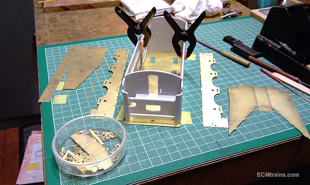
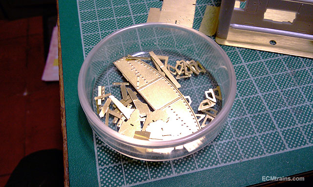
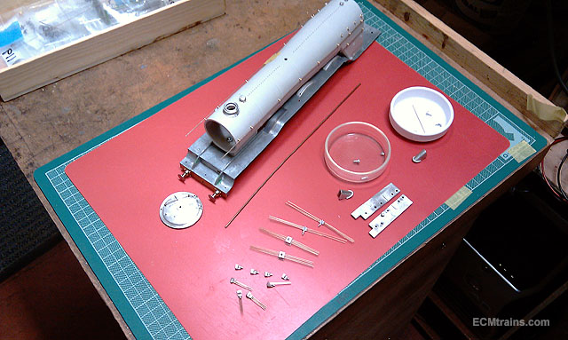
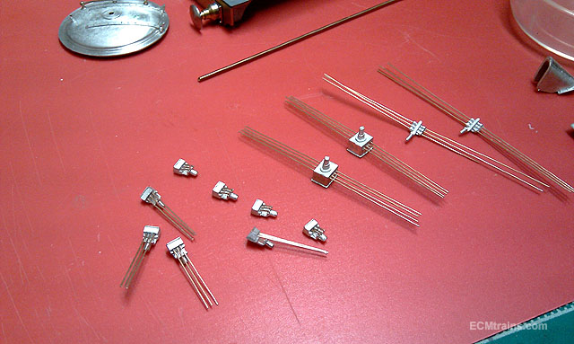
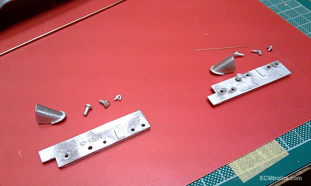
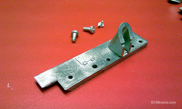
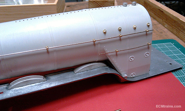
Thanks guys for great coments I started on the upper tender stuff on the Flying Scot, a lot of cusp removal from the brass parts and sized up everything to plan it out. The upper tender section will be removable, I reckon this is better for painting and it allows disassembly if problems occur.. it also allows the tender inside to be accessed if one wants to install anything at a later date Working out the system to assemble the tender structure without using the footplate, the plate will be fixed to the chassis detailed above, so then the plastic structure and all the bits assembled on it will be removable.... Lots of little bits required two evenings cleaning up All the set up work is now complete on the footplate parts of the loco and now getting ready to stick things on Lubricators, atomizers, and .4mm PB wire pipework setup to go on the valve chests on the footplate- a lot of little holes drilled... Valve chests ready Firebox washout plugs installed and boiler handrails test fitted and ready to be stuck on A hold up again as the parts to support the break steam pipe that runs from the smokebox back to the cab are missing- should have some split pins that should work- off to look see.... Eoin

-
It's a transition DART- used to train the drivers while they waited for motors and other stuff to be installed Wrennie Those 'Ribbons' draped on the side- to me they look like protection coverings falling off in the wind! Eoin
-
Great photos Wrennie People did bash the DART at first, even Mr Fitzgerald who brought it in was afraid of it's first run and stayed away, ever the opportunist Mr H (cant bring myself to say his full name...) went on the first run and stole the credit.... after it came in the bashing was in regard to, that there was not enough of them and those stupid folding seats were silly! it transformed commuting in and out of the city... the Luas is doing the same Eoin
-
Hi Guys The Luas has been an incredible addition for the commuter, we are just fudies because we like real trains! and it's lack of good authority road management and cars that cause all the trouble...... Back in the 70's the Dublin Development Plan had the underground planned, it was indicated on the development maps including locations of stations n all- the powers that came along after decided to abandon the plan on the basis of the disruption to the city while building it!- decent tunnelling machines had not been invented then... Eoin
-
Hi Paul Check out here;- http://www.electrarailwaygraphics.co.uk/ and keep an eye on here;- This system will allow a number of loco types to be made in RTR and in kits- still early days but plodding along I also do Gauge N 2 car DART and a Kato 103 conversion DART Eoin
-
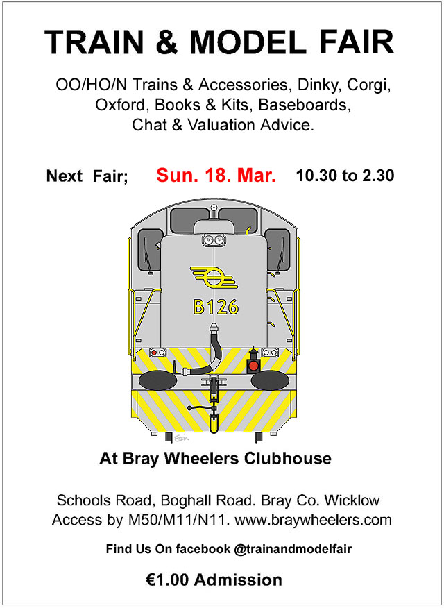
Hi Guys Just a reminder that the Train & Model Fair is coming up this Sunday.......
-
Hi dave182 It's not necessary to go back to metal a light sanding with fine wet n dry fine paper or a soft fibre brush to create a key for the new paint will suffice, then a good wash and your away painting, some models have to much paint applied in the factory and with a second paint detail starts to disappear- these models need a good sand down to retain the detail- Oxford apply a lot of paint to their models.... Eoin
-
Hi dave182 In my experience most die cast models are held together through the floor plate with two screws or stud rivets, unscrew or drill out the rivets and the lot should dissemble, sometimes glazing is spot glued in so try some glue remover on it, when drilling rivets- less is more! as in, only remove the head don't drill into the stud proper as you will need it to assemble the model again. With the stud type one uses a bit of cyano on the stud will hold the model together again..... I use enamel paints Eoin
-
Me to
-
Hi jhb Yes I have dabble in live steam- Stuart stationary and bits, currently working on a 3.5" Northumbrian kit and have designed a 3.5" Hibernia!!- but both shelved for the moment with all the other stuff going on...... Eoin
-

All- Sold MIR 4 Wheel Wagons for Sale, 2 White Metal / 3 Resin
murrayec replied to Georgeconna's topic in For Sale or Wanted
Hi George Are the kids DCC or Analogue? Eoin -
Hi Robert PM sent Thanks Eoin
-
Hi 16miller Many moons ago I built SM32 locos and wagons for a chap's garden railway using Peco mechanisms for their 0-4-2 tram and Hunslet 0-4-0, they had planned to build a live steam railway but baulked at the cost of building the models and went for electric power. Unfortunately he is not on the forum and I have not heard from him since the time of the build- it got complex...... Eoin
-
Hi Robert I have two sets left in the last batch I made, €25.00 per set, €5.50 standard post to GB or €11.75 registered post to GB I'll pm you with account details if you want to order Eoin
-
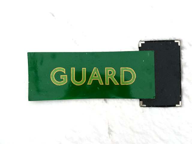
Hi popeye The best way to take a photo is to take it in diffused daylight with a white background and a pure black object in the scene, the camera white balanced before you take the shot, then the levels can be adjusted using the black and white colours in the photo, once you have B&W levels set correctly one has the best colour representation on screen for that situation. Most cameras and phones now have facility for white balancing- this is done just before taking the photo in the same environment you want to take the picture, done with a white sheet of paper held arms length away from the lens, then balance the camera, then take the shot of the model. The GUARD sign photo was taken like this- daylight, white snow background, and black cover book in the shot, then the levels of the photo were adjusted in photoshop (most decent bitmap graphic editors have this facility) and then the green background colour was assessed on screen with the board in the fist to see if it gave a good rep..... When comparing colours in an image its best to do it in the bitmap graphics editor- ie, photoshop, where one can see the values of RGB, or whatever the colour format your working with, and also in greyscale! our eye perceives tones of grey far better than colour- graphics editors have all these facilities for proofing images.... Your photo of the model body you painted seems to be taken indoors under artificial light with a cream background- the light and background will effect the way the camera sees the colours of the model and that is why the photo looks different to the real thing..... Eoin
-
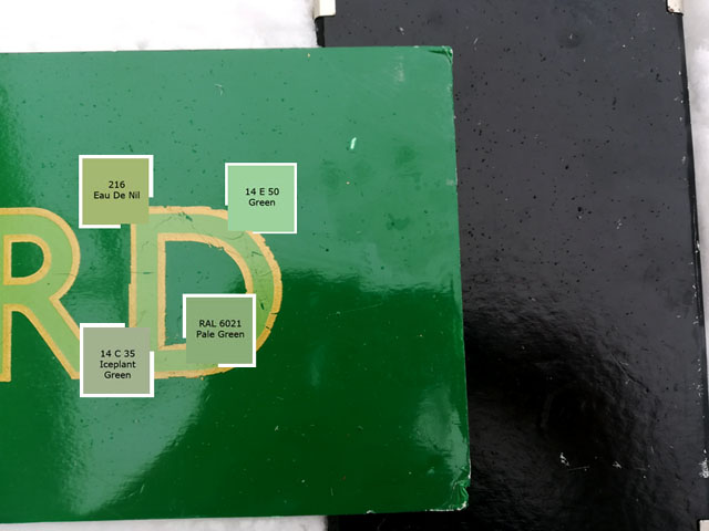
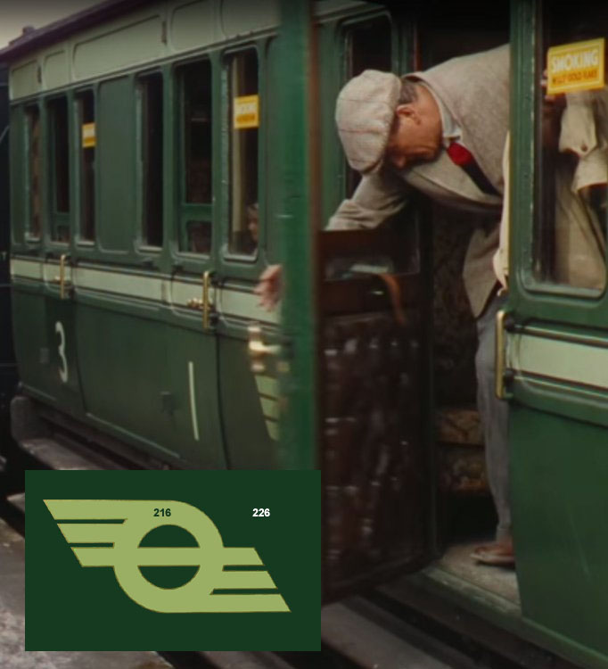
Hi Guys I got this message back from my railway historical source;- "Looks good to me. Sticking to what I said after looking at different screen it's a close as feasible to the real thing. Fourm post can be updated 216 is the best option its the closest" Eoin
-
Hi Guys The plot thickens I contacted my excellent railway historical source to see if he could shed some light on this subject, amazingly he has a GUARD sign which he photographed and sent me, I adjusted the levels and pasted in the colour references we have been discussing and sent him the image, he and an assistant have viewed the image with the board in his fist and conclude that 216 is the closest match The transfer is an original CIÉ 1950s The paint green came from carriage shop Inchicore by Cyril Fry. The board is foam board nó undercoat two coats of paint not varnished. The transfer was beginning to perish but not "yellowed" Transfer is not sealed. They are going to view it again on different screens and see if they have the same opinion on 216 and come back to me. I have also discussed meeting up with him and going to a paint supply system to get an exact reference match and some paint to do a test What a nice thing to have I shall report back Eoin
-
Hi johnminnitt They are the same, I gave the image as for comparison right or left, one or other, but not mixing them In setting up the samples I used the movie image to extract the colour of the snail/stripe and then used the same palate of colours to select the closest match to the BS colour cards- 14 C 35 comes the closest for that image- if you have an other image your referring to post it up and I'll do the same process to it Eoin
-
Hi Steve With the last image I posted, I reckon hold off on doing anything until we see comments back over a few days! After doing this exercise this morning my preference is now for 14 C 35 on all the EDN colour- lined snail, unlined snail, and the body stripes- and not use 216 at all. On the lining;- I'm sure you thought of it- the lines could be in short lengths to make it easier to apply, and the below window line goes through the door handles- I can give you dimensions for this off a SSM 6 wheeler kit if you require? Eoin
-
Hi Guys Just to connect this thread with another on the same subject about paint & decal colours for future reference;- and there is another one;-
-
Hi guys Furthering on the EDN colour, I've gone through the standard RAL & BS 4800 colours and come up with this! The EDN colour on the right is from BS 4800 colours- this range is more common and available in all paint stores, one range is 'Dulux Trade' which is called something new now! (it's an old Dulux brochure I have- but the BS reference will not have changed) BS 14 C 35 is called 'Braemar' by Dulux and 'Iceplant Green' by others- in photoshop it's pretty close though?? There is not a green like 226 in the standard BS 4800 colours- the closest is BS 14 C 39 but leans towards the blue side! Eoin
-
00 scale corrugated iron sheeting
murrayec replied to jhb171achill's question in Questions & Answers
Rendered the scene with a little bit of snow last night.....
-
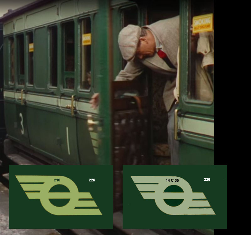
The colours on top of one of Glenderg's adjusted frames from the movie, this also shows the stripes above and below the windows Eoin