murrayec
-
Posts
2,775 -
Joined
-
Last visited
-
Days Won
70
Content Type
Profiles
Forums
Events
Gallery
Blogs
Everything posted by murrayec
-
Hi TinTin Looking good, your flying along.... A hand held hot wire foam cutter is the tool for cutting the board with minimum mess, Proxxon do a nice unit 'Thermocut 12/E' but is a bit more expensive than most, it's advantage is that it has an articulated arm and allied with solid .85mm nichrome wire one can cut all kinds of shapes. Woodland Scenics, Hobbies are others..... Do a goggle search and take a look at the photos Eoin
-
Hi TinTin Not sure if you are referring to a paper OS map or the OS map website, the website is very handy and here is a link of the Historic 25" map zoomed in on the Bray Station, not sure if the settings are retained in the link;- http://maps.osi.ie/publicviewer/#V2,726897,718756,11,9 Also, You might be aware of the Bray Enniskerry Railway?, it was almost built- a lot of ground works done, when things went wrong for the company and the works were abandoned to the scapman. It ran from the terminus at the Cattle pens at the eastern side of Carlisle Grounds and swung west to the Bray River (The Dargle) and followed the river up to Enniskerry- it could make a nice talking point on any Bray Station layout! Eoin
-
Hi Northman Yes, Mr Murphy paid a visit to the show mid morning, carrying a big box in his hands looking like santa, he stopped off at our table to have a chat about the models, a very nice man, 15mins later I had my pack off Wrennie....... Eoin
-
Hi TinTin Great project, I have always planned to do a model of Bray Head, I reckon it will be in Gauge N- to fit things in! Looking forward to seeing your layout develop Eoin
-
Borithe Some very nice layouts, great to see Eoin
-
Mr Musk is joining the IRM team and we all get a slightly singed used car? Is there a prize, is there a prize? Eoin
-
Wrennie Keep me a pack Eoin
-
Landing a probe on Titan, sending images and data back also?
-
Hi Noel I'm sorry but I believe you are in the same fantasy movie Mr Musk is in! there is a purpose to all the low orbit space tech going on, building up the foundation work for doing the 'harder things'. Its small steps over time that lead to Giant Leaps, based on sound research tech, tried n tested over again which leads to big and hopefully safe success- not blasting a car into space and being unable to control where its going. NASA and some of their buddies have a relatively good track record, although they have killed in the region of 300 people in the process, they are building on previous experience and hopefully will do better... NASA's program for a manned mission to Mars seems to be structured well, they are developing their system over a long time- a more experienced base structured system (Mr Musk would not be in position today without all that has gone before) and believe their manned launch time is 2050 or thereabouts. Their not planning space tourism or a commune on Mars, its R&D on the path of 'harder things', they plan to send them up do the work and bring them back, if successfully they move to the next step..... No one is planning a probe to another planetary star system, some are developing propulsion systems for the future- ion drive, partial drive, solar sail... etc and they are the future, also for fantasy movies and Nova TV. Its our planetary system their interested in and they know the limitations..... Eoin
-
Noel An incredible amount has happened since the Giant Leap For Mankind! the Hubble telescope, Huygens, Cassini, James Web telescope, the comet lander, all the Mars Landers, the gravitational wave telescopes, and all the other land based visual & IR telescopes, the Space Station, the satellite systems, the China moon lander last year - the list is endless....man! Eoin
-
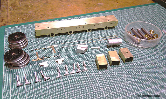
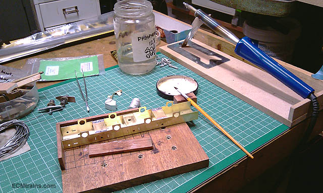
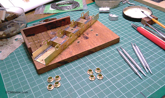
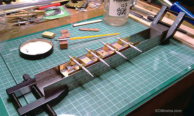
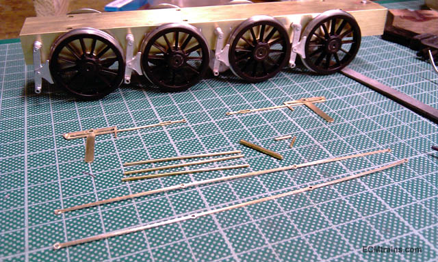
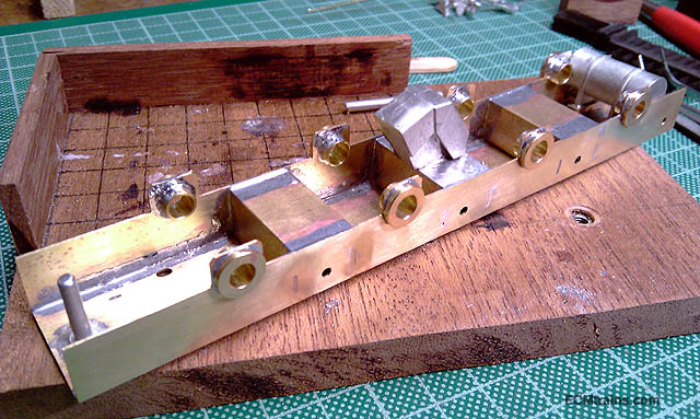
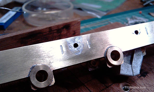
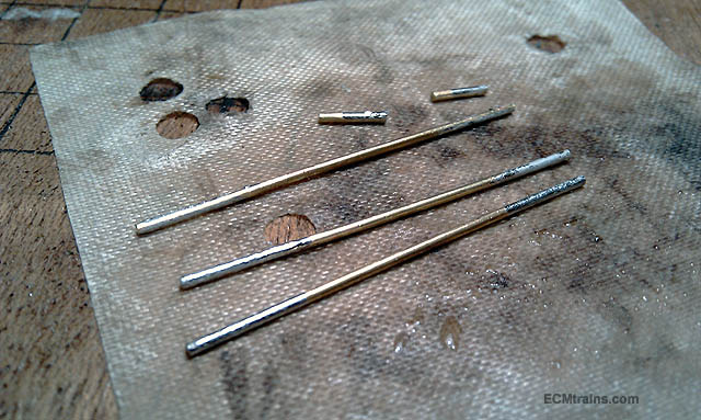
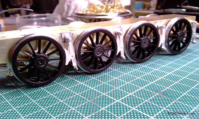
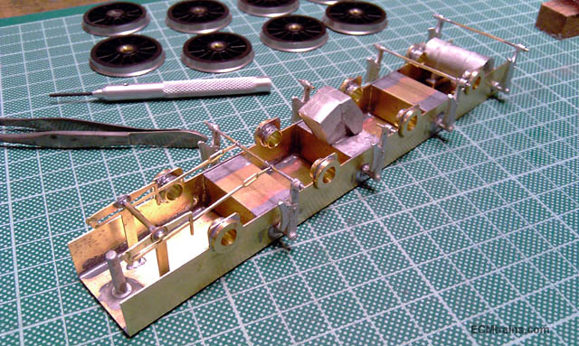
Flying Scot tender chassis All cleaned up and ready to go, spent a few hours removing the cusp and getting things all straight again Out with 100watt Iron, 180deg solder and sizzled some flux I sussed the axle bearing issue- the two centre bearings are over sized for the bends. In the previous build they had been installed in the wrong place! Jigged up and ready to solder, 180deg again in at the back of the bearings Bearings done and underframe stuff soldered on with 70deg solder after the brass was thinned with 180deg solder Wheels on and break gear test fitted ready for soldering Wheels off again and all brass areas to take white metal pre thinned with 180deg solder Same on the break cross rods Wheels back on to position the break shoes for 70deg soldering, I decided to not solder the break pull rods on, as there is 2mm tolerance between the pull rods and the wheels and I cannot see any way in getting the wheels off if their soldered on. They will be epoxied on after painting is complete. I did use the pull rods to get everything lined up for soldering and this is a photo of the set-up Soldered up and a good wash A bit of a sand blast and ready for painting..... Eoin

-
Well now, Thats a bit embarrassing! Lucky he chose a Mars Test Dummy to send, and its only a car and not a space probe as I was suggesting above- phew! Tell Fran that it might be best to hold off on that pack of bubbles until Mr Musk takes a few more swings at it- sure if he does it enough times one will land on the putting green!! I'll bring me soda rocket to the Stillorgan car park on Sunday, if Fran brings the pack, we can see what we can do! Eoin
-
Hi David Amazing street, great workmanship, it has a nice ould feel to it..... Eoin
-
even handier, one could sleep all the way to Mars.... We better stop this, we're a bit off thread.... Eoin
-
Spot on Broithe, I reckon that would be very handy, I see also it comes with pens- a bit of cost saving there! Eoin
-
I believe their looking for candidates who can handle high speed vehicles, and on/off switches for blue flashing lights Eoin
-
Noel Forget 'green credentials' relating to launching rockets! sending people out into space to their doom is a far worse crime, on earth we put people away for this.... Eoin
-
Noel Sure its all there for you curtsy of Mr Musk- stick the rocket together and then throw it into the microwave until slightly brown on the edges...... Eoin
-
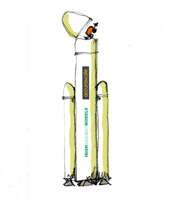
Hi IRM Very disappointed with you guys that Mr musk got there before you! I know he has loads more money then you but your rocket would not be as big as his and it could be made out of lightweight materials- though I do recommend using metal near the engines just in case - plastic might melt with the heat.... 'Space Bubble' Eoin
-
Yes pretty cool technology, it is a great development for getting into space and keeping costs down- such a pity that their first test lift flight was a car, something that's totally useless in space! Would have been far better to have programmed the test lift with a necessary space exploration probe- many are been worked on and need to get into space, but hay that's American Candy Shop Corporation buzz! At least SpaceX have changed their idea about sending people to Mars and leaving them totally stranded with no escape, they are now talking about bringing them back- this may be to do with NASA refusing to hire out the launch facility to send people to their doom... Mr Musk gave a number of talks last year about their plans for the Mars missions, its like a Fantasy Film- I read in the Geographic last year SpaceX had 25,000 applications to go to Mars after the release of 'The Martian' He claims that their system will move 1 million people 100 at a time every two years to Mars in about 40 to 100 years, and Mars would be terra-formed by the time the 1 million are there! He doesn't seem to be able to do the maths- one spaceship will move 5,000 people in 100 years!, he will need 200 spaceships in the proposed time scale. Also previous estimates in terra-forming Mars are 500 to anywhere near 1,000 years and there is a big doubt that it can be done- one theory on the Mars atmosphere is that it was once like Earth and the atmosphere leaked out- whats to stop that happening while terra-forming it again, its all guess work at the moment. He also talks about building a city on Mars for the 1 million Martians, a surface city, but says absolutely nothing about the radiation problem that exists outside our severely protected Earth. A large solar flare without Earth protection is instant death- one of the main reasons astronomers/cosmologists believe Mars is dead. The people working on the radiation problem while going to, and staying on Mars, recommend living 20m under the surface, under solid rock- cant do that in a spaceship. They could bring a radiation protection vessel on board the ship, but that would take up all the flight payload- though they could use it on the surface to live in until they dig the mine..... Mr Musk mentions none of this! He also says that an initial flight ticket will cost 250,000 dollars and may reduce to less than 100,000 later on. When he was asked about who they would choose to go on the first human flight, his first words were 'if your prepared to die you can go'... 'it's going to be pretty risky at first'.... 'but hay you got to live it up'.... He also said that the first flight would be in 2022! In the same Geographic article mentioned above it said;- after SpaceX achieved the first booster return and landing in 2016 Mr Musk announced that they would be sending people to Mars in the next couple of years- NASA said 'Not from here mate' Its interesting stuff but....... Eoin
-
Thanks Guys I agree David, scratch building is less fettled, I think its because it's us designing and making the parts as we go and not a chap at a drawing board who will never actually build the model he designs! Thats not throughout the kit designer industry, but I have had some major problems with kits, and also, read about it..... Eoin
-
Hi Noel I'd be very worried about what I would get for €50.00 inc free delivery to Irishland- sure a courier would charge approx £30 to move an item that size- not much left over for the cabinet!! Eoin
-
Hi Noel One cannot buy from Picture Pride, one has to go through their agents and Marks is the Irish agent- not sure how strict this is. If I told you how much CM paid I'd have to shoot you, and CM would probably shoot me.... Go onto the Picture Pride website and select what you want, then give Marks a call for a quote Eoin
-
Hi Noel David does do them, but this is a Picture Pride job thru Marks Models Eoin
-
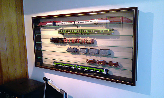
A vertical storage yard was installed at Greystones Layout recently;-