murrayec
-
Posts
2,775 -
Joined
-
Last visited
-
Days Won
70
Content Type
Profiles
Forums
Events
Gallery
Blogs
Everything posted by murrayec
-
http://www.lendonsmodelshop.co.uk/pdf/Bachmann OO Service Sheets/Class 3f Jinty.pdf
-
Hi George Diarmuid of Weirpark Books who will be there, has a lot of Plane kits, he recently purchased a huge collection and there is a great selection. I picked up an X1 at the Bray Train & Model Fair last Sunday off him and there's a few more that I fancy- Plane Spotting at Stillorgan.....
-
Hi Robert When you get the first bend done and inserted in the jig, then with the same pliers clamp the wire to the jig, you then adjust the wire so that the end through the jig is perpendicular, hold tight near the other end and then bend the end over the edge- if done correctly the two returns are then in the same plane. Eoin
-
Hi heirflick Last I checked about 3 months ago nothing had happened Eoin
-
Hi JHB We made an attempt to offer our assistance to the project group to aid and support the cause to get the Fry Model out of storage, this was done before the design plans were made, but we were told that they would be delighted to talk with us after the design was complete!..... I made a submission during the planning process, to my amazement they did take on board some of my comments- additional 35sqm added to the exhibit area and revised the toilets to be internal! to mention a few. But alas these will not be enough as they do not realise what they have...... Eoin
-
Hi All This months BRM magazine has a mention of the Fry Model in an interview with 'The Little Layout Company'- in response to the question about working on layouts it's mentioned that they are looking at a ''Colin Fry Layout''! that's kept at ''Dublin Castle''!, the interviewee goes on to say- 'the room that it's in was getting damp and the layout started getting destroyed, but they want us to go over there and put it back together in a new purpose built exhibition area.... Eoin
-
Hi JHB Mr Coakham's book IBGC has a photo on page 44 of heating van No. 3131 sporting aluminium livery Eoin
-
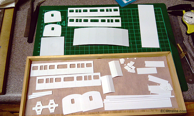
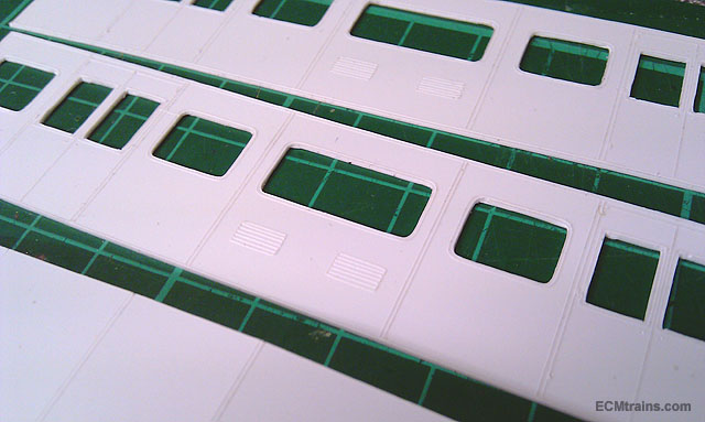
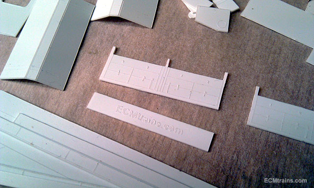
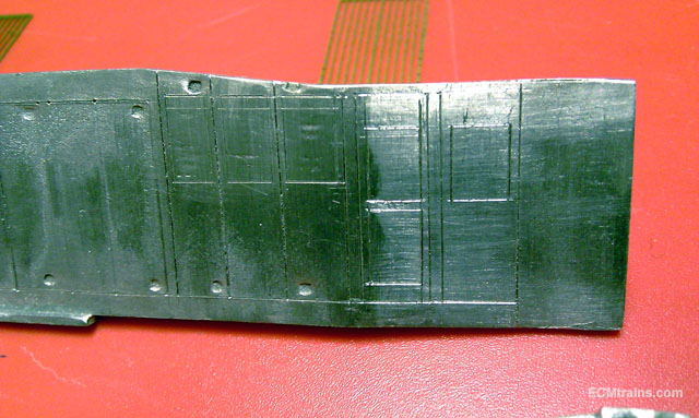
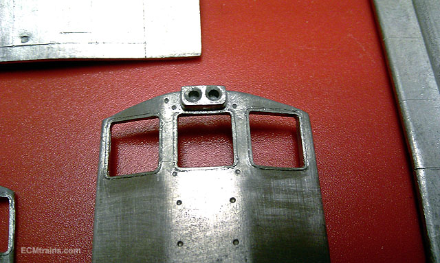
Hi JHB As I mentioned to you last week or so, I was raging that I missed John's kits, so I'm making my own, here are a few photos of it being developed up.... The parts for two Heating Vans Scribed on detail Roof , W Irons & Spring parts being assembled to make moulds off I still have a bit to go but all is working out well.... Eoin

-
until
-
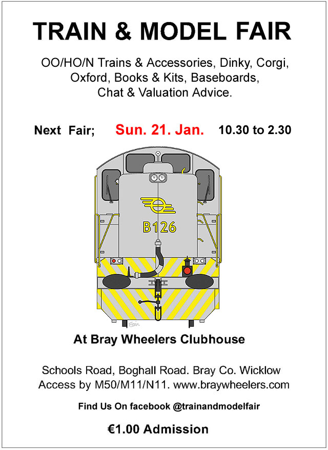
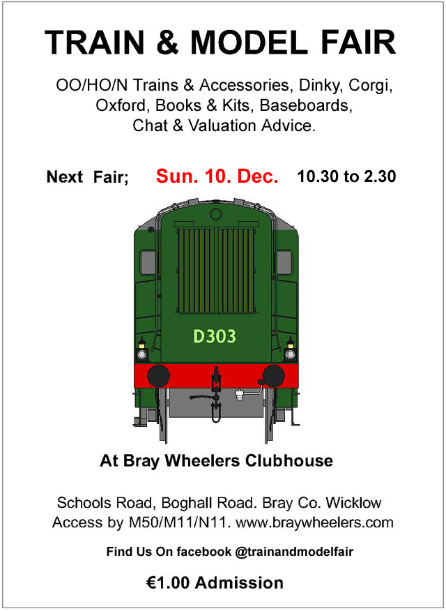
Hi All & a Happy New Year The 2018 Fairs kick off on Jan 21st, as this is supposed to be the year of the 121 we have set an appropriate graphic for this years flyer.... Hope to see yo then
-
Here is one that popped up- sort of in the same vein... http://wicklownews.net/2017/12/miniature-village-taken-from-garden/ Eoin
-
josefstadt There was a chap who had a model railway in his private garden near Kilcoole on one of the roads from Newtown..... he used to let people in, sadly the house was sold and the new owner had no interest and the layout was dismantled, I think in the early 2000's Here in Kilmac there is a 3.5inch track, a big circle on very nice pre-cast concrete arch system, built a long time ago and now disused, the current owner has left nature to take it over and it wont be around for much longer... such a pity! Eoin
-
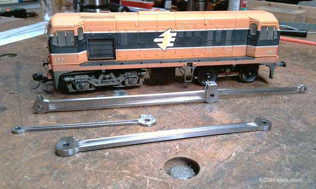
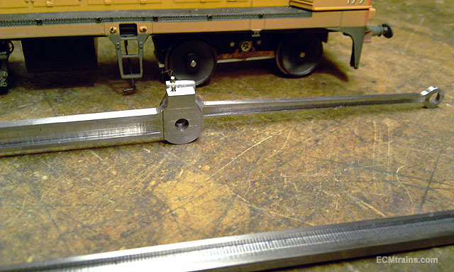
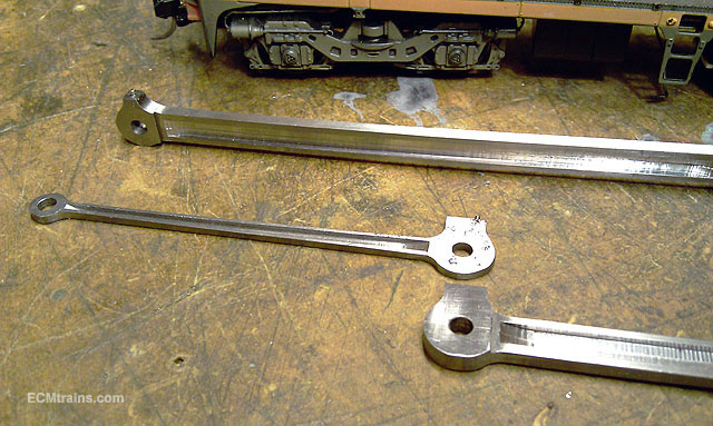
Hi Here are a few photos of a set of Coupling & Connecting Rods for a Gauge 1 GNRi Class VS, fresh off the bench. They were machined from mild steel EN8 flats & sheet, the coupling rod axle centres is 103mm, I thought I'd photo them up against my trusty Gauge 00 171 for scale comp. The tapered route in the connecting rods was a bit of a task, it required a jig to allow the rod to swing a bit to allow cutting the taper route in the mill. Little lengths of .8mm NS wire are loctite-ed in a drilled hole to imitate the plug on the oil boxes on top of rods- ready now for their owner and I look forward to seeing them run...... Eoin
- 1 reply
-
- 5
-

-

-
- gnri class vs
- machined rods
- (and 1 more)
-

Walker Diesel Class F - ECMbuild in 4mm for OOn3
murrayec replied to murrayec's topic in Irish Models
Excellent find, great detail and of great help I'm currently waiting Chinery bogie parts and etch rods n counter weights, all available but have to wait! Eoin- 136 replies
-
- 1
-

-
- class f
- west clare
- (and 1 more)
-
Excellent Noel It looks great and done very neatly Eoin
-
Hi Candle wax is the best, preferably paraffin wax type- if you run out of spit! I keep a block of it on the bench (i've had it since I was about 9) and drill into it before drilling the hard stuff, its also deadly when used to lubricate the piercing saw.... also my experience with the Expo Drill Sets is not good, I found on the really small ones the factory grinding to the business end was hit n miss- but replacement bits from Expo are excellent..... Eoin
-
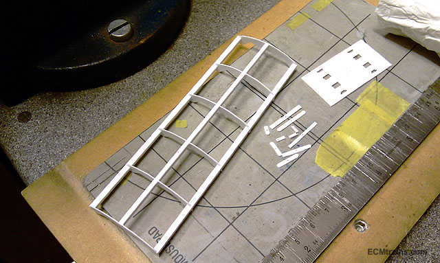
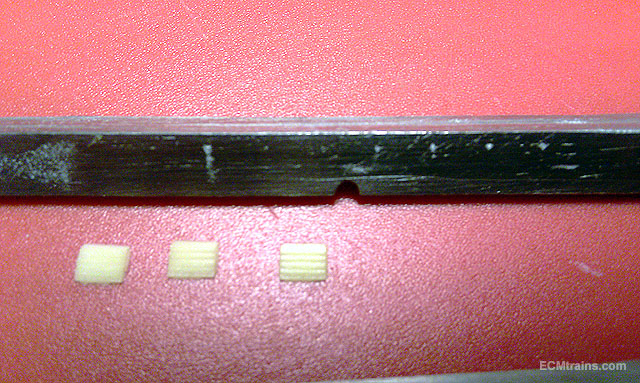
Hi The ICR looks great I'm amusing the 121 is a white metal kit- the door panels and joins can be marked out with a scalpel and and then with an old blunt school compass point to make them a bit deeper, the lovers are another problem! I have wiped them down and am replacing with plastic cast ones.... Plastic cast louvres ready to go on to the valance Here are the windows with extra frame detail added with the dividers from the same school compass set Eoin
-
21mm gauge track; the pros and cons?
murrayec replied to jhb171achill's topic in Irish Model Layouts
Hi JHB Incorporate a section of standard track into the layout for visiting locos, and keep a bit of stock to run with it, it could be an automatic straight shuttle section?? Layout just below eye level is right, but do keep in mind it's nice to be sitting down when running trains.... Eoin -
21mm gauge track; the pros and cons?
murrayec replied to jhb171achill's topic in Irish Model Layouts
Hi JHB Your existing J15 and the 141 should convert relatively easy, the 141 as far as I know has bogie sides that allow the wider wheel sets! Any new build can allow for at the onset..... C&L Finescale, Marcway, etc do parts to build yourself or build to order- although C&L are in a slow down with ownership change! and it costs a lot more.... Edit; Actually I'm told C&L are back up to usual speed You should talk to baseboard-dave on this he builds C&L layouts, there maybe a solution there! Eoin -
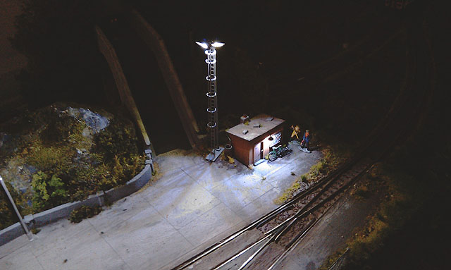
CM I'd be in the switch box! there is a stove in there.... Eoin
-
Excellent David Classic little model, I see the driver has weighted down the front end with the sacks of spuds.... Eoin
-
Yes definitely trains on the other planets! - back in early days Lowell was convinced he could see through the scope, canals and high speed railway tubes on Mars Eoin
-
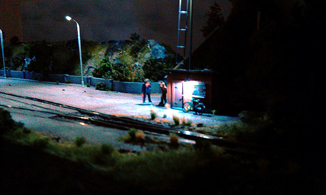
Hi All Dark and cold winter nights setting in at Greystones..... Eoin & CM
-
Hi David Lovely chassis, love the chain drive Where did you source the chain and sprockets? Eoin
-
Hi All Don't forget the Train & Model Fair is on this coming Sunday;- Info about the show can now be found on facebook @trainandmodelfair