murrayec
-
Posts
2,775 -
Joined
-
Last visited
-
Days Won
70
Content Type
Profiles
Forums
Events
Gallery
Blogs
Everything posted by murrayec
-
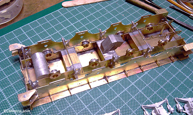
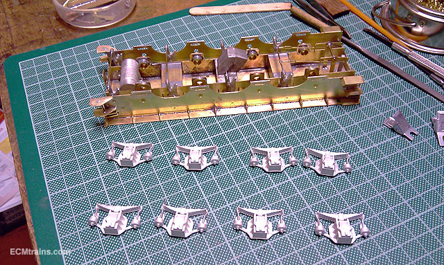
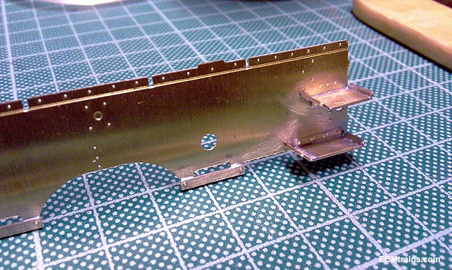
Hi Guys thanks for the great comments Some more stuff on the Flying Scotsman tender;- I bent up the coal bunker and top of tender plate, a bit of persuasion to get it into shape, taped it up and tack soldered it and then got it into final shape for soldering all over All worked OK and fits almost like a glove- surprising.... Some small adjustment done to the bunker front as the tender front face would not sit in properly, mainly metal filed off..... The first of the front tender parts, cut out, cusp removed, folded up, soldered up, and cleaned up Footplate, frames, drag beam, buffer beam, and brackets prepared for soldering up Soldered Chassis test fitted Axle springs on next but the brass work needs a clean up in the blast cabinet first Eoin

-
Hi TinTin The accident was reported to have happened at the 'Brandy Hole ravine', as far as I'm aware the location we are discussing is the Brandy Hole? this is going by local history, I also assumed this was the only cove that had boat landing and access up the head by a ravine for the smugglers When I first saw the wood-cut image I saw it as this ravine, in discussion, and not further South, but looking at the three images you posted has helped me to understand the photo in the Permanent Way book- the third image is the same as in the book, the rocks always puzzled me- the rock formation on the sea side lines up with the rocks in the other two images! This is a link to a report on the accident in the Freeman's Journal, 10 August 1867 http://www.greystonesahs.org/gahs1/index.php?id=386 Eoin
-
Hi TinTin If you look at the image I referenced above, on the South side of the bridge one can see a square platform under the track-way a short distance from the ravine edge, also on the Northern side note a small trestle supporting the track-way above the ravine edge- so the track-way seems to have been elevated above the structures of the ravine and the ground level If it was a crane structure! it would have been built after the new line was complete, it could not have been built before because the old line was repaired and used while the new stuff was been built! Why would they use a crane to take stuff up from the sea (if that's what your thinking) when they have the existing track to bring materials in, and risk of boats founding on the rocks below! There is another photo, worth a look, of the bridge after the accident- page 20 of 'Tales of the Permanent Way' by Michael Barry. The author dates the accident in 1865, it also indicates that the track on that side was raised, it also indicates how much artistic licence was used in the engraving image! Eoin
-
Hi Guys That's the remnants of Burnel's 2 trestle timber bridge spanning the Brandy Hole Ravine, I reckon. In 1867 a train with passengers crashed off the bridge into the ravine due to poor track maintenance, 2 died and many were injured Here is a link to a engraving picture, an artist impression of after the accident;-https://www.magnoliabox.com/products/bray-head-ireland-1867-scene-of-the-accident-on-the-dublin-wicklow-and-wenford-railway-kerry-liszt-060430-0678 Eoin
-

Easter 2018 PW workings on the network
murrayec replied to dave182's topic in What's happening on the network?
Excellent video, great to see Love that big crane- especially the counter-weight system hanging off the back with its mobile deck manoeuvring around under the weights- deadly Eoin -
Wexford Model Railway Club Exhibition Easter 2018
murrayec replied to Irishrailwayman's topic in What's On?
Well done John , lovely layout and well done Fran, lovely wagon Edit;- Oh and well done dartstation on your award for the SDMRC layout Eoin -
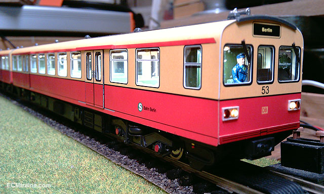
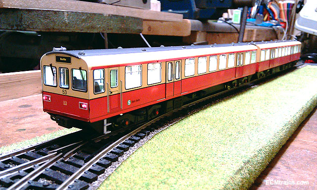
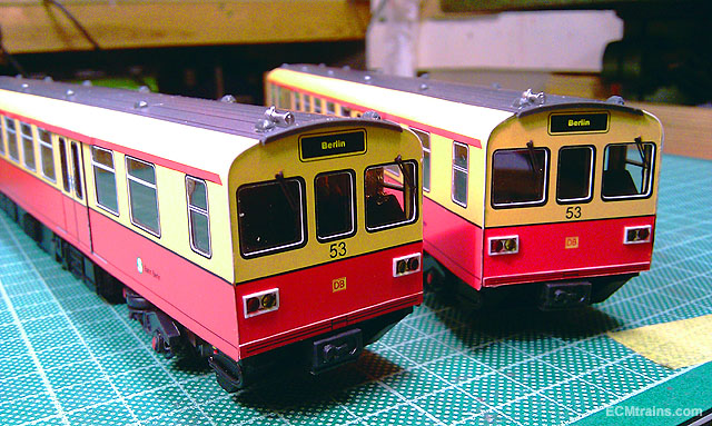
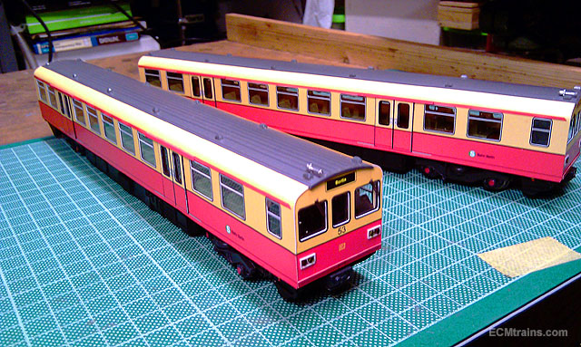
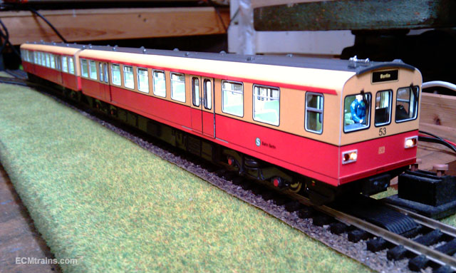
Well with DART models on TV, n all!..... Here are a few photos of the completed S-bahn- a project on the go for over 3 years! It's done.... Just a few little touch ups, into the box and will have it on show in Wexford over the weekend Eoin
-
Oh! the fame, the fame!! Thanks guys, I have not seen it yet but me Mum recorded it Eoin Edit;- Just saw it on the RTE player, great DART coverage- I wonder is there something wrong with the second set's internal lights? The show was a bit one-sided, very much on the negative.... Eoin
-
until
-
Creating an On-Line photographic Museum
murrayec replied to GNRi1959's topic in Photos & Videos of the Prototype
If one wanted to display a collection and is concerned about protecting their rights to ownership, one could set up a site with, say Wordpress, that displays photos in a thumbnail format only- low enough resolution to preview, but no use for printing or zooming in unless permission is granted by the host- this could be done by request, then granting access permission to the user, or emailing the photo to the user. This requires work and monitoring by the host but does allow the collection to be displayed with a reasonable amount of control and compiles a database of users that permissions have been granted to, if issues arise..... Eoin -
Hi Broithe Sid Meade used to do futuristic city & vehicle calenders for a Japanese tyre company, one of his designs was self cleaning streets- the street was in sections and had different faces like a drum, when they needed cleaning they rotated to bring up a new clean face..... Eoin
-
Hi Noel Disconnect the battery unit from the light strip, and install it under the chassis with wires back up to the strip- then you can pop the battery out easier! A tail lamp can be added to the strips at the end, the dots on the strip are soldering tabs to add additional lights- don't forget the resistor.... Eoin
-
Hi Borithe It's an exceptionally neat and tidy station! Eoin
-
I recently had an enquiry on converting an Oxford truck to the Faller Car System, so I thought I'd add a link in here to make it easy to find how I did one in the past, I posted it in my projects thread in 'Workbench' some time back - here is a link;- Eoin
-
- 1
-

-
- oxford conversion to faller
- oxford
- (and 1 more)
-
Hi btb A very small unit if you plan to do a lot of painting, you'd be far better off getting something a bit bigger in the compressor area. Here is a link to the kind of unit I use;- https://www.expotools.com/acatalog/AB603-Airbrush-Deal-AB603.html#SID=2 Lidl do a full size tanked compressor from time to time for around €100.00, one would need a filtration system €20.00 in Lidl (not the best unit- SIP do one for around €100.00) Lidl's one does work, it's a water filter n oiler- the oiler you don't need for painting! then the spray gun and a few connectors. These compressors are OK quality and you have the added advantage for use in other applications- pumping up her tyres! Eoin
-
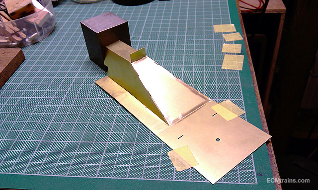
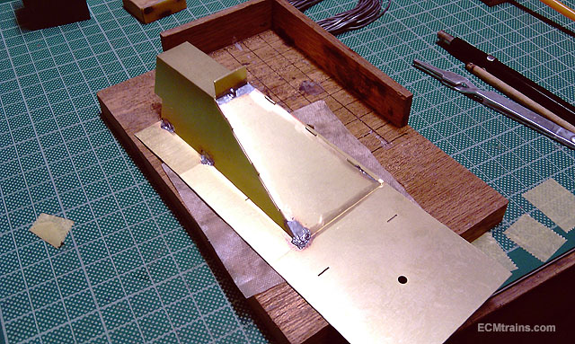
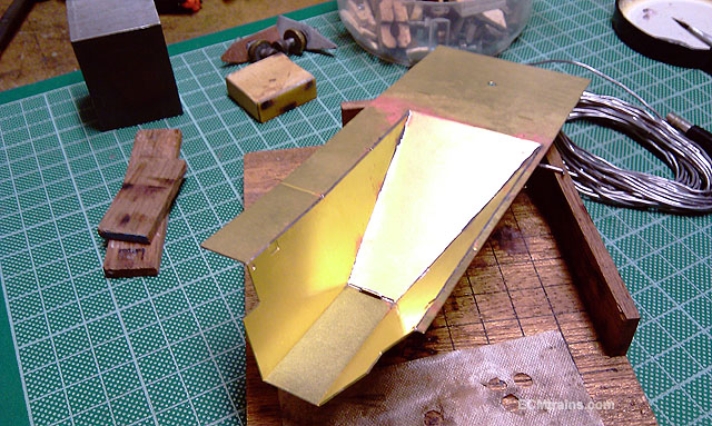
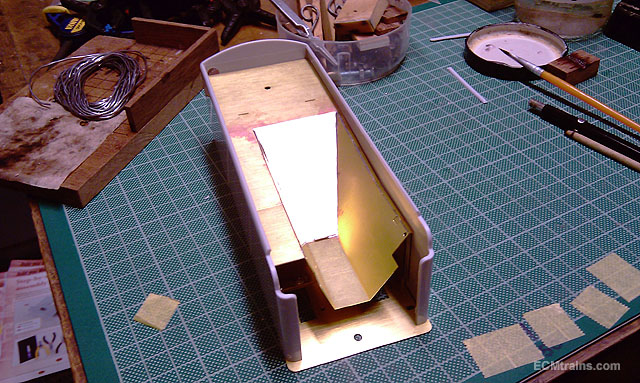
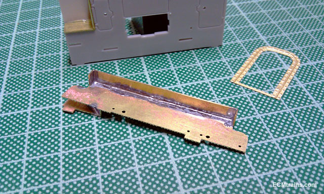
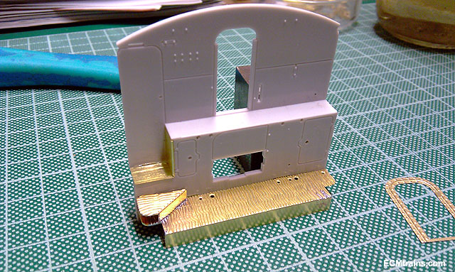
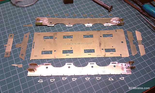
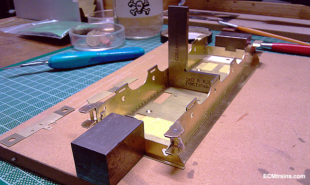
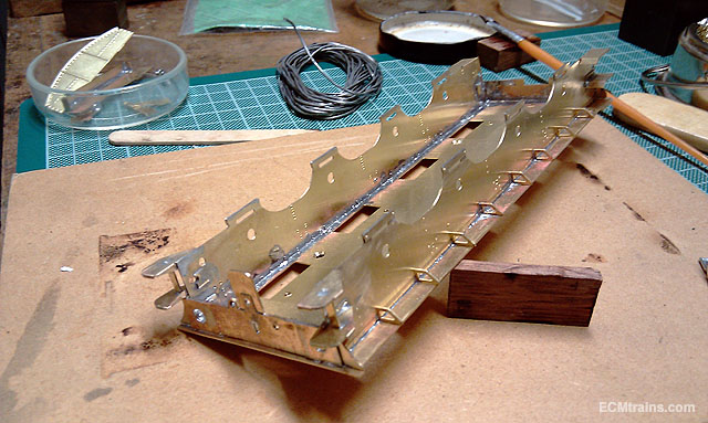
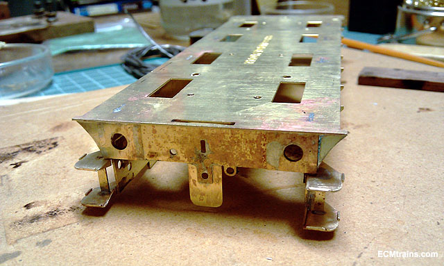
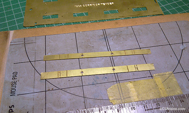
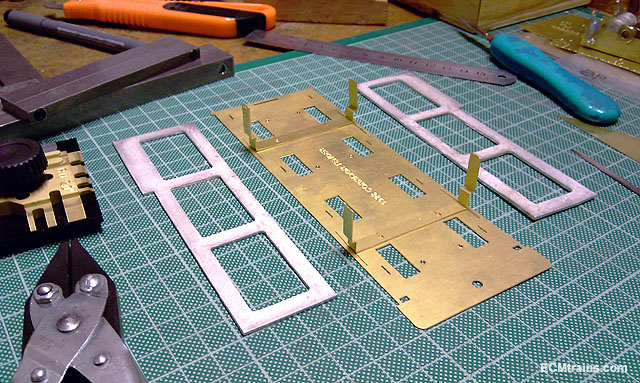
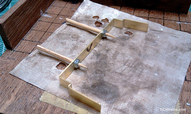
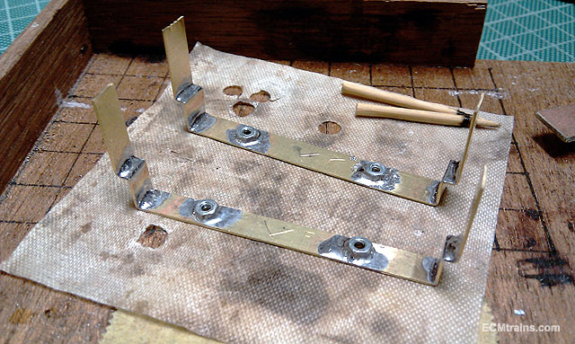
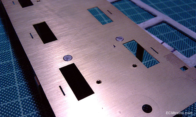
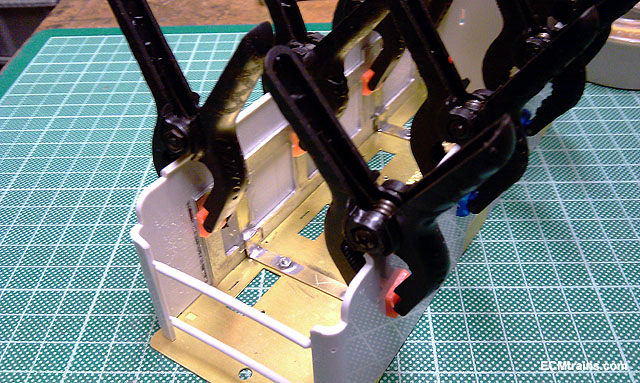
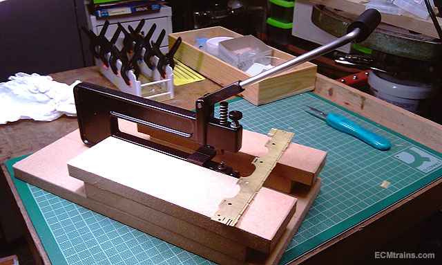
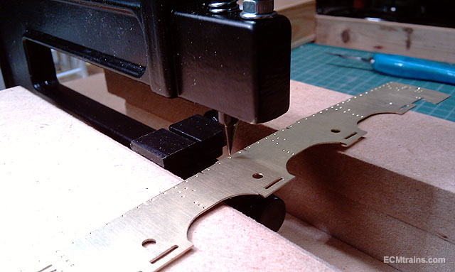
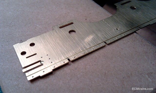
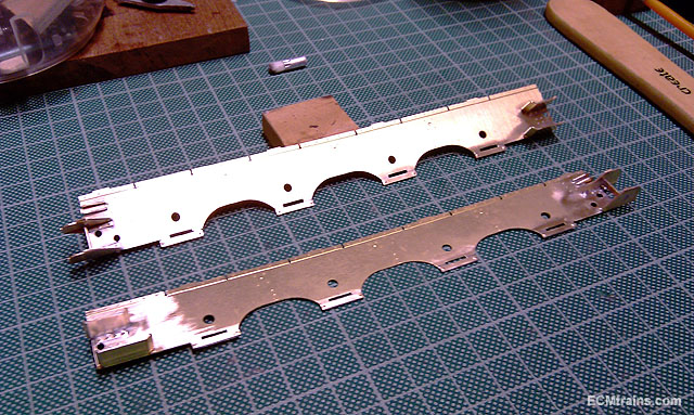
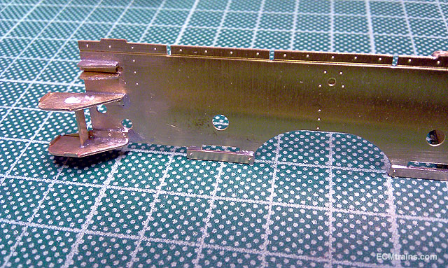
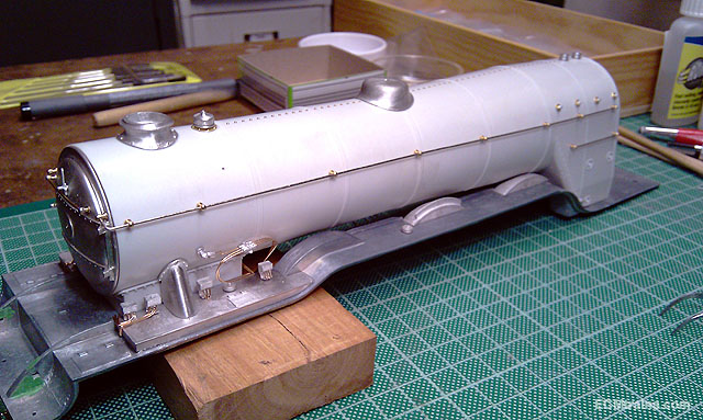
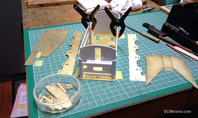
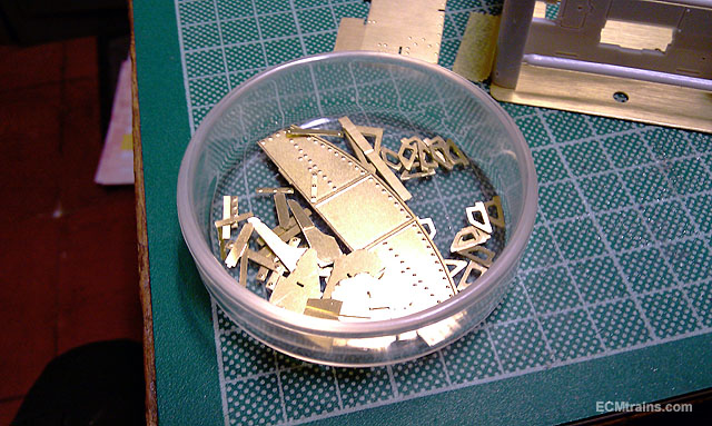
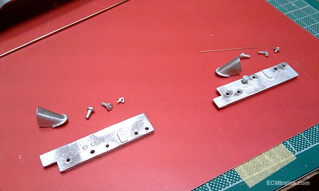
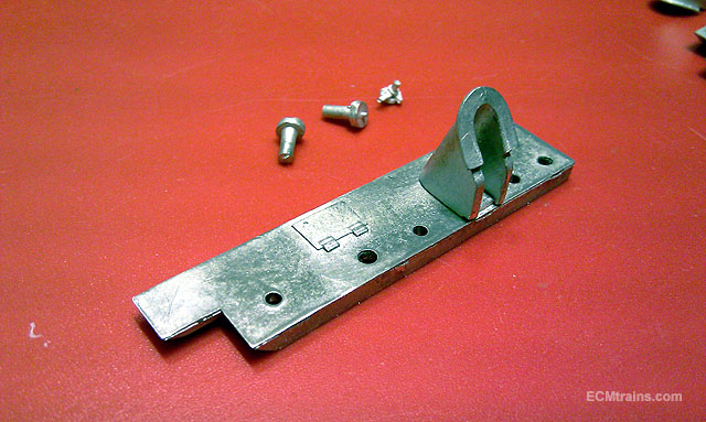
Hi all So with the Bray Fair cancelled on Sunday I had a bit of spare time- Flying Scot upper tender body time! With my plan on being able to remove the upper body I cut some waste brass sprue to make two brackets to hold it together on assembly, straps cut, scored for folding, and M2 bolt holes drilled.. All folded up and setup to mark holes in footplate Captive M2 nuts about to be soldered on, using the excellent modellers tool to hold the nuts in place- cocktail sticks! All soldered up with 180deg solder, soldered the folds also for a bit of rigidity M2 holes in footplate were countersunk for the screws After a few minor adjustments the upper body was installed and the unit was epoxied, making sure the footplate was not glued While that was setting I started on the tender main frames, these needed the rivets embossed out first, the kit has half etched marks for this This is a very handy rivet embossing tool which I made a new MDF table for, and I get to try it out for the first time here- its hard to hold a part in place with nothing to rest it or your hand on when using the punch, it works really well Nice little embossed rivits I then soldered on the frame steps, steps rivet detail, and the axle box keeper plates with 180deg solder All cleaned up and frames now ready to be fitted to the footplate Eoin
-
Hi irishthump There are different grades of alcohol spirit, I suspect them Americans use a specific grade for mixing paint? I have a bottle of isoprop from a pharmacy that melts any soft plastic or rubber it comes in contact with, skin also!..... Eoin
-
I have to agree there with thumper- surgical spirits is not the best for cleaning paint, paint doesn't dilute in it like it does in thinners, spirit can also melt O rings and plastics that some guns have..... Eoin
-
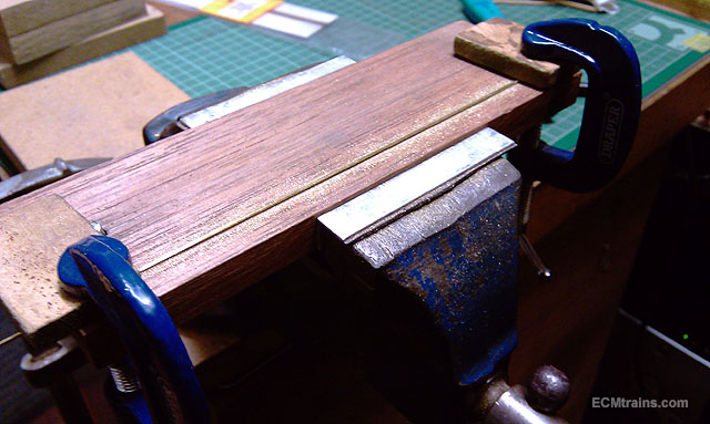
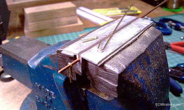
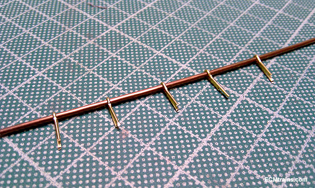
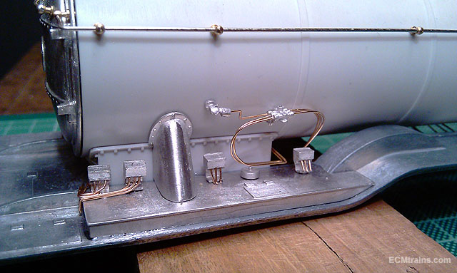
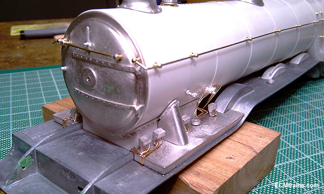
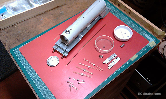
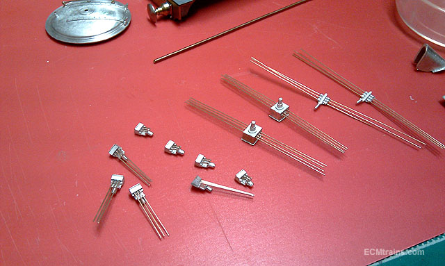
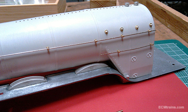
Cant believe it! not a split pin suitable in the workshop. So set about making up a few out of .8mm brass wire Clamped down in the vice on a piece of hardwood and filed the wire flat on one side Then measured off 5 lengths, bent them over the PB wire steam pipe, cut them, and then pinched each with a pliers to form the eyelets Split pins With that done I started to fit the lubricators, atomizers, and pipes- this photo shows the steam pipe installed with the split pins Hand rails completed with wrap around over smoke box door rim, lubricators, atomizer and pipes installed on this side All complete and very close to start painting- small bit of straightening up and a bit of filling here n there Its great to get this job completed, I wasn't to sure how the pipes were going to work with my plan of being able to remove the boiler from the footplate for painting. It does work but some of the pipes will have to be installed after painting- otherwise it worked out Deadly! Eoin
-
Nail on the head, John, with Noel and his 30mins Eoin
-
Hi All With the recent discussion on the Luas and in that thread the mention of an underground railway for Dublin City- I thought of doing this thread so that some of the people interested in, or against, can view the technical and design aspects of a project like this. Some may find this very boring and not applicable to their argument, but it is real information and has to be considered in the discussion for reasons of;- cost, technical & design ability, build ability, feasibility, and the affect it would have on the City while under construction. Some of these points if not all are the reasons why an underground has been promoted in the past and then abandoned! So here we go;- This is a truncated report by the Institute of Engineers of Ireland on what's under Dublin City- some argue that its all rock but the report indicates what's actually there;- https://www.engineersireland.ie/EngineersIreland/media/SiteMedia/groups/societies/geotechnical/Soils-of-Dublin.pdf?ext=.pdf This is a lecture by Michael Löffler from CDM Smith discusses the use of underground space as a key factor for sustainable development of densely populated areas. He outlines innovative solutions to these challenges from a number of ongoing and recently completed underground rail projects;- It's interesting that the Institute hosted this lecture only last year? Please contribute to this thread with any information you think is relevant and please link to the source of the information that you add, so that we have qualified additions that can be referenced and not just notional personal thoughts- qualified information leads to good understanding of a development like this...... Eoin
-
Hi Noel I reckon the ultrasonic cleaner has caused this problem- it is known that ultrasonic cleaners can cause metal fatigue by vibrating the crystals to the point of destruction- the glue in the metal lets the hard particles go and under pressure or working the item breaks. I would recommend keeping precision tools and metal models (especially ones that have been super-glued or epoxied) away from ultrasonics..... Eoin
-
and For those masking problem areas use liquid masking applied with a brush into the raised area under the masking tape, let it set then tidy it up before painting- Humbrol do it or you can use the liquid masking one gets in the Art n Hobby Shop Eoin
-
Hi Noel Use cellulose thinners to clean your spray gun, cellulose will remove all paint if you spray with it after quitting painting, use it after spraying the paint thinners to wash the gun out first, or when cleaning the gun use it and/or leave it soak in it for a few hours- spanking clean every time.... If you have paint getting into the air in area there is a problem with the gun? Eoin
-
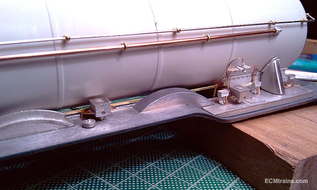
Thanks guys for great coments I started on the upper tender stuff on the Flying Scot, a lot of cusp removal from the brass parts and sized up everything to plan it out. The upper tender section will be removable, I reckon this is better for painting and it allows disassembly if problems occur.. it also allows the tender inside to be accessed if one wants to install anything at a later date Working out the system to assemble the tender structure without using the footplate, the plate will be fixed to the chassis detailed above, so then the plastic structure and all the bits assembled on it will be removable.... Lots of little bits required two evenings cleaning up All the set up work is now complete on the footplate parts of the loco and now getting ready to stick things on Lubricators, atomizers, and .4mm PB wire pipework setup to go on the valve chests on the footplate- a lot of little holes drilled... Valve chests ready Firebox washout plugs installed and boiler handrails test fitted and ready to be stuck on A hold up again as the parts to support the break steam pipe that runs from the smokebox back to the cab are missing- should have some split pins that should work- off to look see.... Eoin