murrayec
-
Posts
2,775 -
Joined
-
Last visited
-
Days Won
70
Content Type
Profiles
Forums
Events
Gallery
Blogs
Everything posted by murrayec
-
Hi MikeO An excellent model, more than 'passable' and 'reasonable'- it's brilliant next- now to get it up to an 8 coach Eoin
-
Hi Broithe Not sure about a flywheel, have to wait till he has a look- the blown motor had the shaft completely cut back! and not sure about the make of track he gave it to me for testing, it's nicely made with the metal shoes and slim sleepers but the rails are a bit chunky to my eye, though I will ask on make and report back... Eoin
-
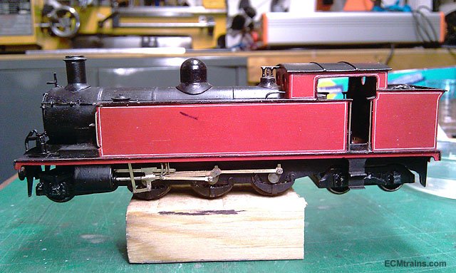
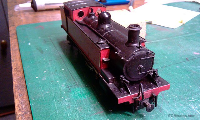
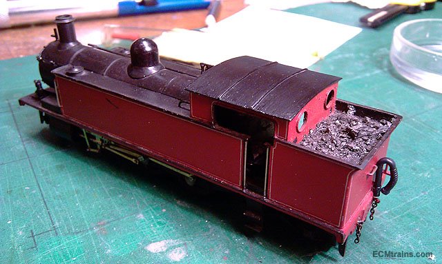
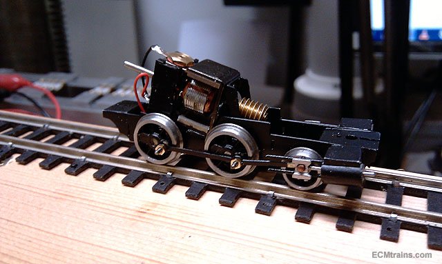
Here's a couple for the gallery, a chap is modelling OOn3 and I had them in the shop for repairs;- A lovely Class 5 Tank requiring attention to dropped valve gear and a 2-4-0 chassis requiring a new motor and full restoration, not sure what goes on top of this! but this might spur him on to post up pictures of other stuff? Eoin

-
until
-
Hi All Next Fair;-
-
Hi MikeO Keep an eye on here, when I do the longer units and work out the cover I'll be posting options and prices Eoin
-
Hi Borithe I do have a design for doing that- the Greystones Layout originally had an elevator storage yard but the powers that be decided against it, it will surface elsewhere in the future! Eoin
-
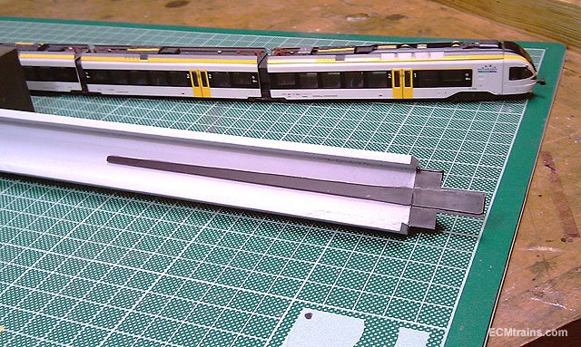
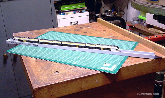
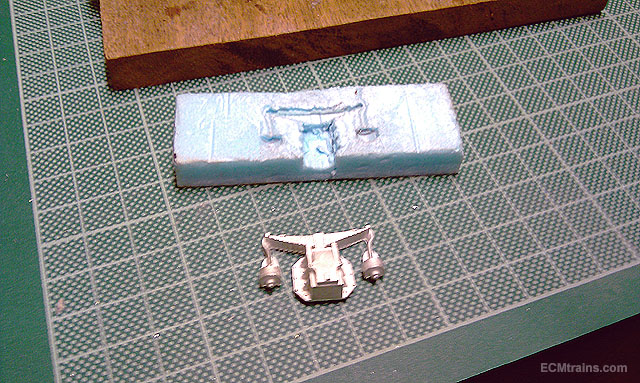
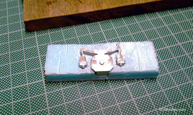
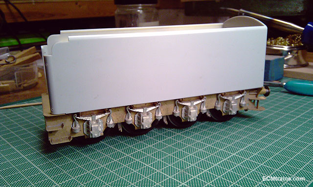
Hi Here is my prototype Storage Cassette, I have made this for a chap who has a number of slinky long trains on his layout, every time he goes to remove them from the track another coupler breaks or springs go flying- as for the Tram in the photos! It is also a manual loader to get the trains off/on the track without lifting them- one drives the train backwards into the cassette until the motor bogie disconnects from the track and then its pushed by hand the rest of the way, going onto the track is the reverse. Each cassette with train in can be stored on shelves to the side...... This one is 610mm long and will be used for testing the idea, the next ones will be much longer for ICE and Eurostar trains and will incorporate a mod to the loader- which will be recessed in the base so the sides of the cassette will protect it. Perspex covers will be available also so the dust will be kept at bay and the trains can be transported in the cassette- though adds to the work & cost Design work still in progress....... Eoin
-
Hi David If it was me I would leave all as is, except for the coal load I would upgrade, give it a good clean n oil and then treasure the model in its current condition..... Eoin
-
Hi David Congrats on your purchase, you have a fine piece of model history there, also delighted to see it added to the history your making with this layout and stock. I browsed through the brochure also and was very tempted on one or three items but decided to hold off as the Midland Railway Centre announced another run on their 12in. precision guillotine which I reckon I'll go for instead....... Eoin
-
Hi John These sheds are generally leased out to local business for storage or to run business from like a fabrication shop if not used by CIE themselves. I know a chap who ran a manufacturing company in a leased loco shed in Dublin for many years...... https://www.cie.ie/property.html I see a container at the far end of the shed, the ivy removal on the gable, the upper window coverings, and the infestation prevention leads me to believe the shed is used in some form or they wish to preserve it- though the ivy is working its way up again! The proprietor of this thread may have further information or photos to assist in this investigation....? Eoin
-
Hi Dave That's bird nesting and pigeon access prevention House Martins and Swallows love these kind of locations for nesting, and pigeons love the interiors to roost in, if they can find a way in they'll take over the place and do other things all over the place! And now with H&S rules it can be expensive to have the place cleaned up. Eoin
-

Is Tomytech TM21 a suitable Chassis for N scale 141?
murrayec replied to purple's question in Questions & Answers
Hi purple The TM-21 is about the right length, a 141 is about 82mm to cab fronts (at 1:148), but you'll have a problem with the 141 walkways between the cabs with a chassis that has stuff above footplate level and flush with the sides- the width needs to be 10 to 12mm max in this area to keep in scale and you'll have to allow for the thickness of the 3D print!! Eoin -
Hi heirflick Wow, That's a Big Box for a little loco..... Eoin
-
Welcome Jan von Daniken says... 'It's an alien space rocket that the Anunnaki left here long ago, the Vikings stole the ladder and they could not get into it! These space rockets were used to transport gold from earth to the mother-ship called 'Nibiru' - the missing twelfth planet! Proof that far more intelligent life and technologies existed before we came along'....... Eoin
-
Yep, that's the man- we can also thank him for the design of the hatch-back car = Mazda 323, and the VW Scirocco, also big private ships for princess and rather rich people, but his best stuff is the futuristic artwork, I have a book from the early 80's about him- one wheel gyro cars, levitating cars that drive themselves guided by a central divide beacon, one wheel gyro personnel transport units one wares on your back, press the button, down drops the wheel and your away.... and oh he has designed passenger train interiors! I bet he would appreciate the architectural quality of this station building- he does modern-futuristic but with an old quality Here is a link if you want to see his stuff;- https://www.google.com/search?q=syd+mead+art&client=firefox-b&tbm=isch&tbo=u&source=univ&sa=X&ved=0ahUKEwjzrfDVjcfaAhWJKFAKHVNJBJAQsAQIKA&biw=1280&bih=890 Eoin
-
-
Hi Noel Do you remember this one?;- Eoin
-
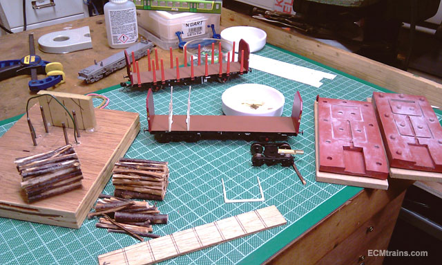
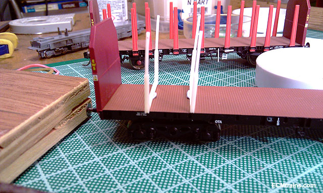
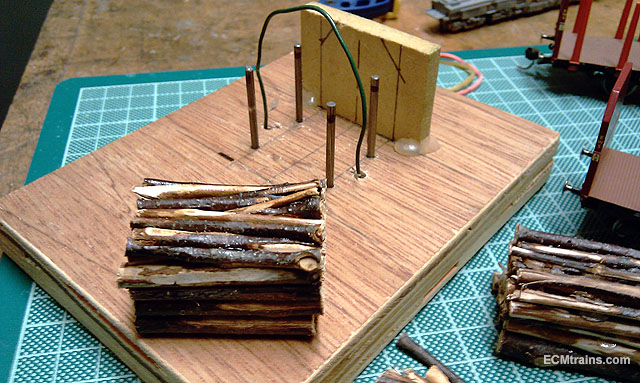
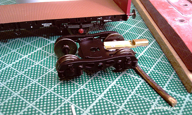
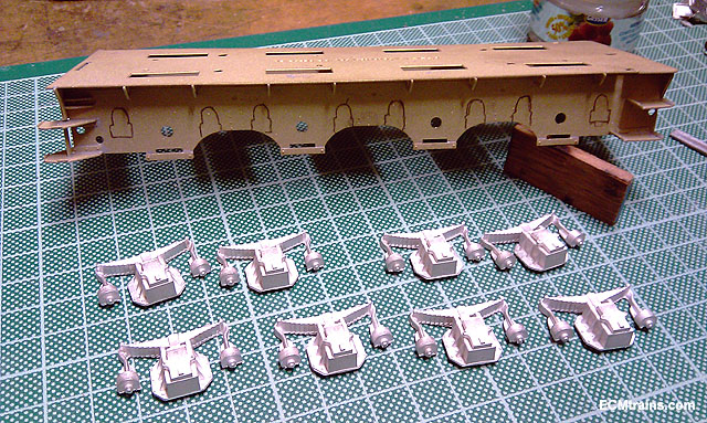
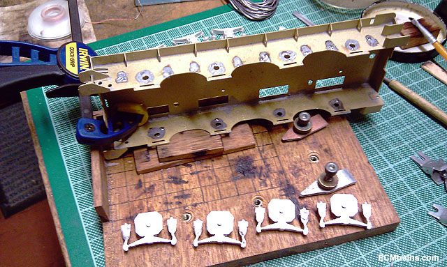
Hi Guys Here are a few photos of an OTA going to bogie'd Irish timber wagons for the Greystones Layout A mould is made to do the uprights in white metal, there will be seven of them with plastic additional beams, ladders n stuff Jig for making the batch of logs from silver birch twigs from the garden, held together with PVA and one will have ballast weight in it Y25 bogie with CNC cut (i can say that now) brass NEM 362 pocket soldered up and ready to epoxy to bogie Not finding much time to finish these, making 3 and getting there slowly..... Looking back at it, the OTA wagon is stripped down so much its nearly worth considering starting from scratch, we are using these because the 3 of them will fit in the station siding and not obstruct the main line- we started with them, we'll keep going..... Eoin
-
Hi jhb Don't think the client would like it in blue, wasn't there a story about one of the restorations on the Flying Scot? - they painted it blue and they got death threats from the fans & sponsors were displeased and requested their money back.... Eoin
-
Hi MikeO I'm still waiting the drawing from my source, I enquired & reminded him again at the Wexford Show! If you do a Google search 'DART 8500 or 8600' you'll find plenty of images including roof details that might help Here are two links which show roof detail in among other photos 8500;- https://hiveminer.com/Tags/8500%2Cdublin/Timeline 8600;- https://hiveminer.com/Tags/8629%2Ctrain Eoin
-
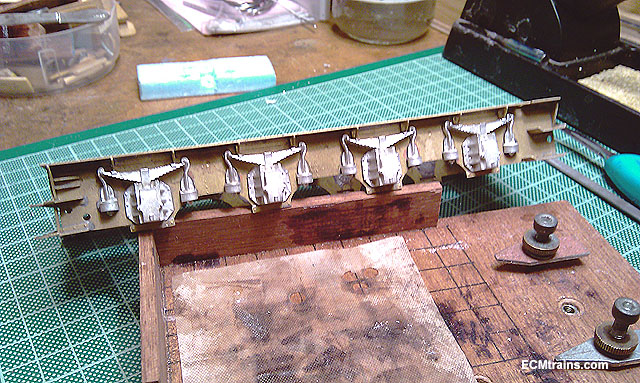
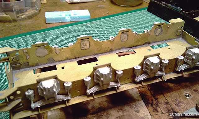
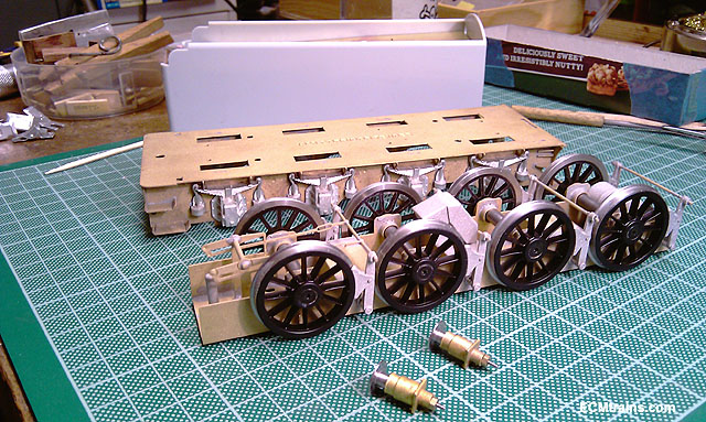
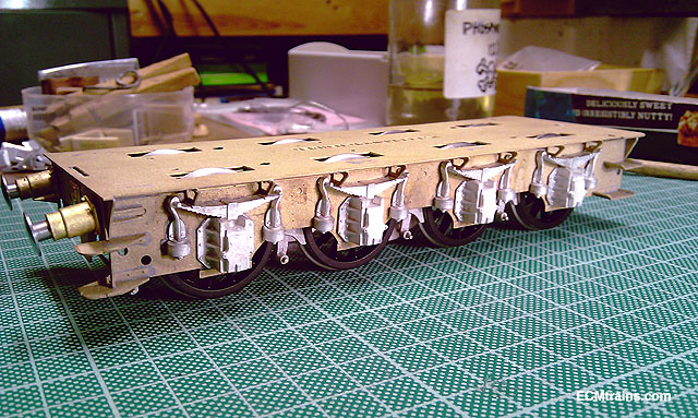
Flying Scotsman Tender main chassis stuff complete;- So the springs needed a bit of cleaning up, the spru ran across the back of the axle box and out the sides to support the spring hangers- this had to be removed, I made a little jig out of styrene to hold the units while filing, I filed down the spru flush and then cut off what was left, the styrene protects the hangers from getting out of shape. The springs required some metal to be removed as they would not tuck in under chassis brackets under the floor plate. All ready to go soldering, note the pencil lead to stop the solder running everywhere- 70deg lead solder will do that! So the plan is to put 180deg solder to the brass, inside n out, and 70deg lead solder to the back of the springs, then sweat solder together using gentile persuasion with a stick! The heat is applied to the inside of the frames, with the frames fluxed again and 70deg solder on the iron. One side done and the pencil lead works a treat, virtually no solder to be cleaned off on the front Other side done, a good blob of 70deg solder used on the back, the iron is held there until one sees the solder flow through to the other side and around the axle box- nice shiny line! All the bits, and wheels back on for...... ....... Oooooh! lets put it together Looking like a tender Eoin
-
Beautiful village, great model village, rivers, chimneys n mill, Red Arrows flying overhead 5 days a week a modellers paradise..... Eoin
-
Yes Noel, it's the water scoop all right, I saw a film of one of these in action, they slow down a bit, lower the scoop and bash water everywhere- hedgehogs and frogs flying! Eoin