murrayec
-
Posts
2,765 -
Joined
-
Last visited
-
Days Won
70
Content Type
Profiles
Forums
Events
Gallery
Blogs
Everything posted by murrayec
-
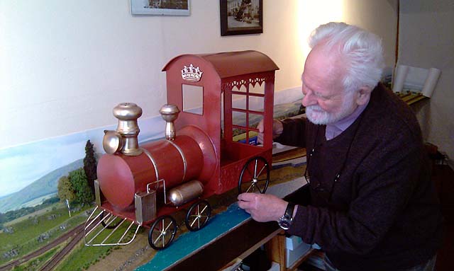
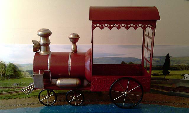
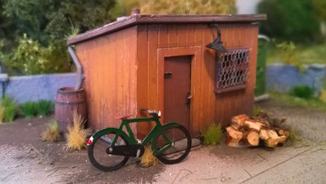
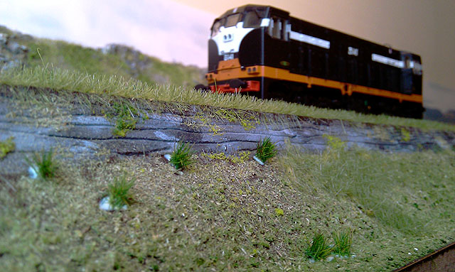
Closetmodeller was away for Christmas and returned with this gem! can you guess where he was? there's a hint of A4-Mallard here me thinks, scale wise...

-
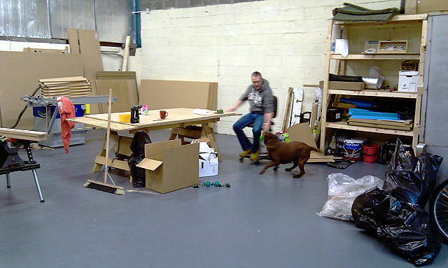
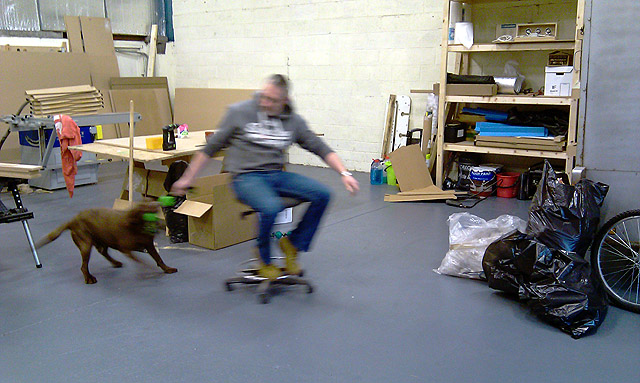
Hi A couple of chaps and myself paid Dave a visit today in his new workshop, an excellent workshop. I think in the end- the rain in Valleymount did him a great favour to encourage him to move to this unit. And I was amazed it takes less than an hour to get there from the M50. We had a chat, moved some MDF sheets, re-hung a door, and one of the visitors did the check on the WC and cleaned the sink. It was great to hear and discuss Dave's plans for the future- we wish and he deserves the best for the future in his new workshop... Very impressed with the catering services! I know I'll be visiting again. This is only for special visitors & customers!! Oh! also impressed with his assistant, who pulls him around the workshop without having to leave his chair.... Eoin
-
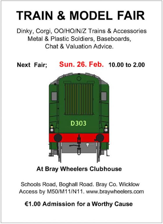
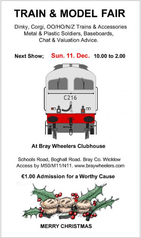
untilAt Bray Wheelers Clubhouse, Schools Road off Boghall Road 10.00 till 2.00 http://irishrailwaymodeller.com/showthread.php/94-Bray-Train-amp-Model-Fair?p=97232&viewfull=1#post97232
-
-
David Looking great, your flying along Eoin
-
The first show of 2017 is on next week....
-
Excellent David Lets see the BigBoy running... Looking forward to seeing this develop Eoin
-
Broithe Stunning photo
-
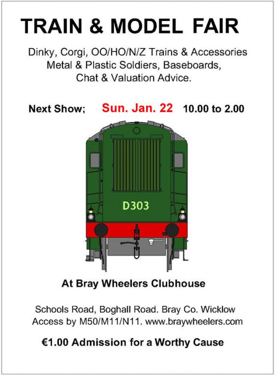
untilFrom 10.00 to 2.00 at Bray Wheelers Clubhouse off Boghall Road. Bray. Co Wicklow. http://irishrailwaymodeller.com/showthread.php/94-Bray-Train-amp-Model-Fair?p=95650&viewfull=1#post95650
-
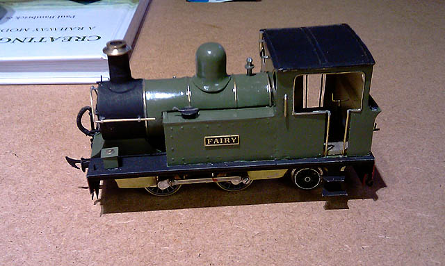
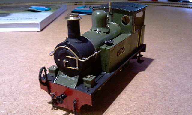
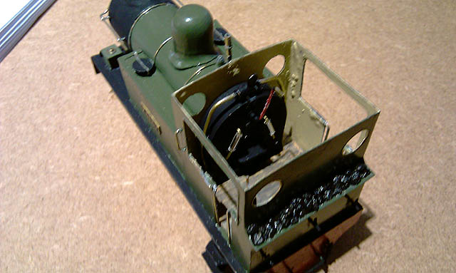
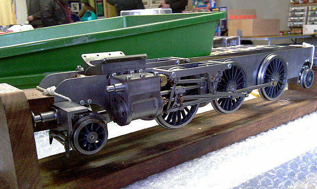
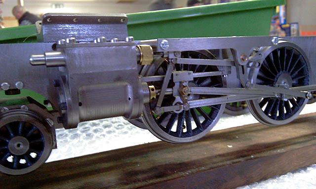
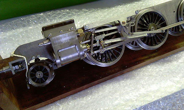
Hi All We had great attendants at the Christmas Fair on Dec 11th, thanks to all who dropped in and made it a very enjoyable morning and Merry Christmas to all..... Two in-progress projects were brought in to show off on the day, a beautiful freelance Gauge O 0-4-2 tank Loco, and a fantastic Gauge 1 2-6-2 Tank Loco Chassis- a live steam model incredibly machined and in another league.... See you in the new year Eoin
-
Hi David Cow-****! Loads of Cow-**** and horse do-do, that's what covered the roads.... I can recommend reference to Mr. 'Robert L. Chapman's Ireland', a publication of part of his photograph collection between 1907-1957. He took scenic photos around the county all featuring roads up close- photos of trains, bikes, motor bikes and street scenes. His famous shots are of the ice-cream vendor selling ices to the spectators watching the army on the other side of the Liffey, duke it out with the Custom House Rebels and burn down the amazing building. His rural shots are classic, they'll take you by surprise as to how little street clutter there was back then and looking at some of the shots of the Dublin streets indicates limited street cleaning, one can barely see the cobbles with all the debris on top- I think the stuff as mentioned above, I'm told the place smelled a bit to! Regards Eoin
-
Excellent David I'd say a dream come true Did you take any photos? Eoin
-
Hi All The final 2016 Train & Model Fair is on next Sunday the 11th, come on in for that present you could not find, and and we'll have mince pies to celebrate Christmas....
-
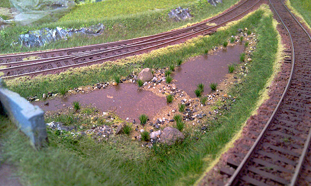
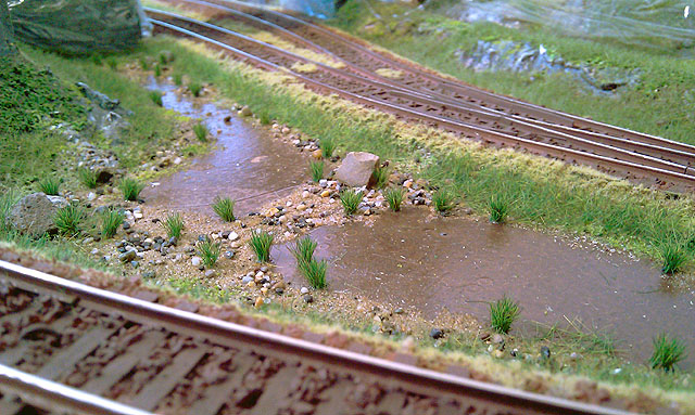
Hi all The shrubbery works very well, we have completed most in the Timber Yard and The Breeches and have now moved on to the reed planting on the sand dunes of the beach.... Eoin & CM
-
Hi Thanks guys for the great comments David & JHB Me to! I have been looking at it sitting on the coffee table for the last few days!! I think we need one of these;- Eoin
-
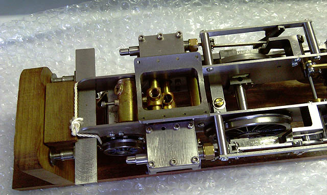
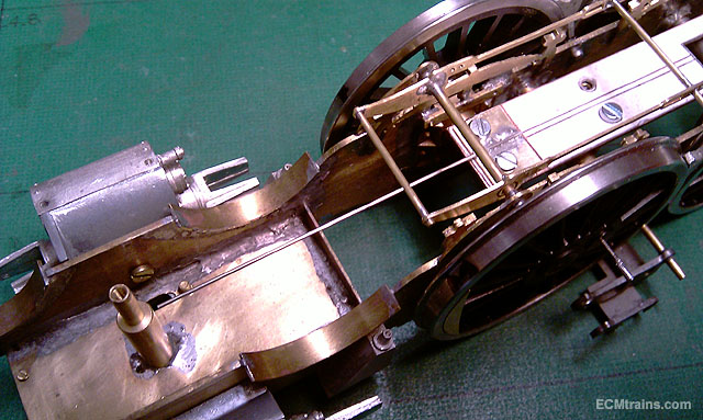
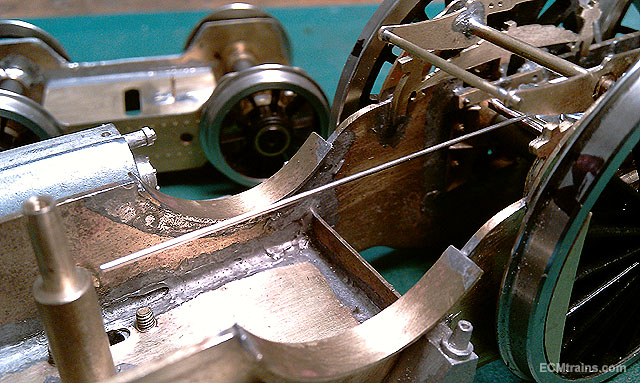
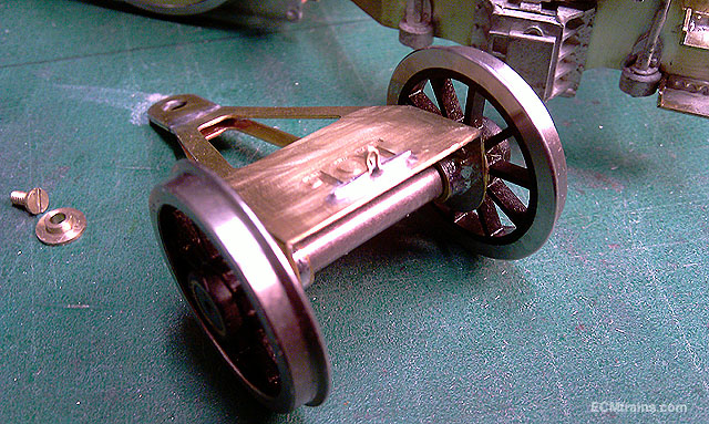
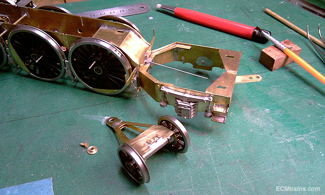
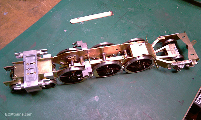
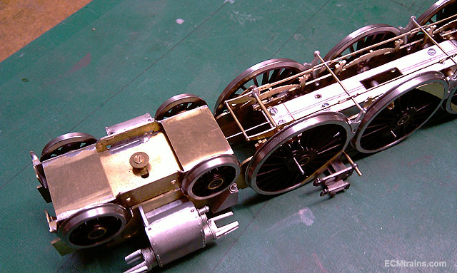
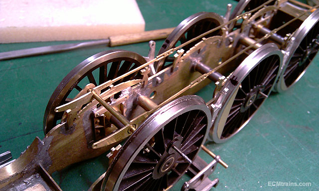
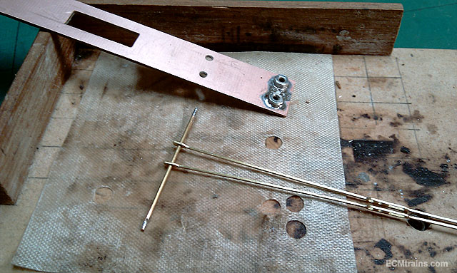
..... WM Break blocks were soldered with 70deg solder to pre thinned chassis holes with 145deg solder and all the break rod assembly soldered up Test assembly of the front truck spring, one can just make out the loop on the truck that this wire will go through to spring the truck- this unit goes in after the truck is mounted to the chassis Rear truck .6mm NS wire centring spring going together, this spring will also put slight down pressure on the truck Just about complete and ready for the paint shop, footplate supports and front wheel guards yet to go on but holding off on that one until the wheels are off and the whole is about to be painted Eoin
-
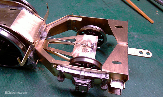
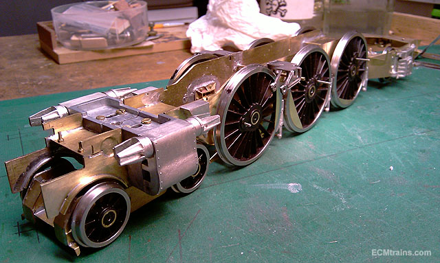
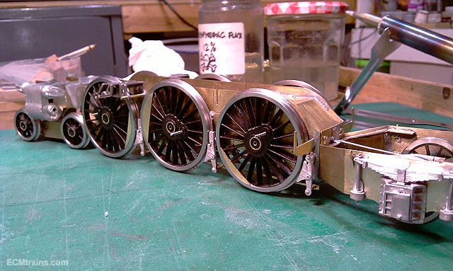
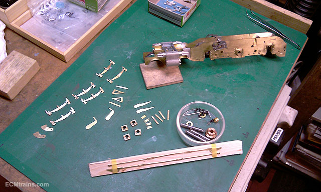
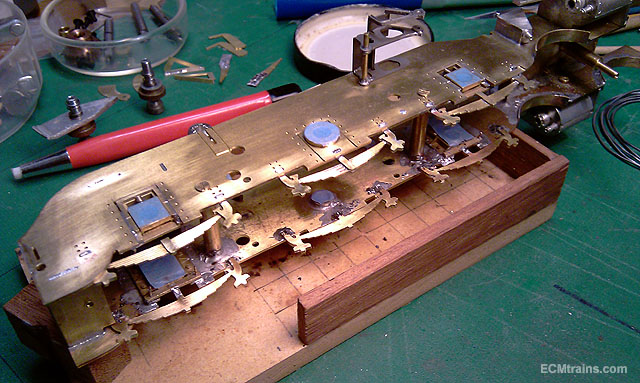
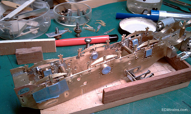
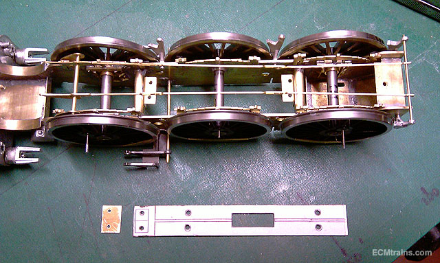
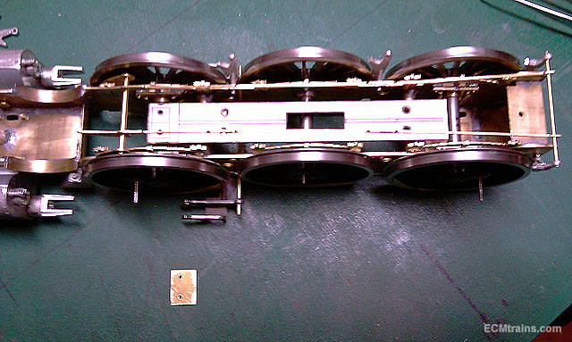
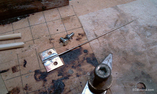
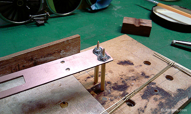
Hi Thanks guys... So then next step is to stick on all the springs, break gear, electrical pick-up board, and bogie truck centring springs. The road springs are laminated with 180deg solder so they will be stuck to the chassis with 145deg, so hopefully nothing will fall asunder... ....and that happened! the chassis is a big heat sink and the soldering station was a bit slow on the regain- loads of heat into the spring components but the heat ran away through the chassis, time for the Big Boy! a 100 watt Weller, no problem now with heat running away, the join was instant. Though one has to be careful.... Road springs and horn block keepers on and a little clean-up required, I stuck small bits of tape on the bearings inside and out to protect from the flux, phosphorous is very corrosive and I'd like to keep it away from them All cleaned up, break gear being test fitted, and the pick-up board being worked out, wiper type pick-ups will be used and the front bogie truck centring spring will be mounted on the front of this board. The board will be M2 screw fixed to two threaded brass angle plates soldered to the frame spacers. There is also a central slot for the gearbox drive gear to stick through Front truck spring assembly soldered up, .6mm NS wire spring with two M2 screws to fix, M2 nuts captive soldered to board for this mounting. The break cross rods have been thinned with 145deg solder in prep for soldering into the WM break blocks with 70deg solder ......
-
untilTrain & Model Fair at Bray Wheelers Clubhouse, Boghall Road, Bray Door open 10.00 till 2.00 http://irishrailwaymodeller.com/showthread.php/94-Bray-Train-amp-Model-Fair?p=94730&viewfull=1#post94730
-
Hi All Them wagons n bubble are lovely.... The show again was very well attended, what with the mess of dates at the beginning of the month! Great to see all and great to see chaps bringing in their current projects to show off- keep it up
-
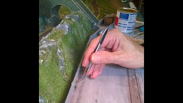
Hi Picked up this nice set of tweezers from Baseboard Dave last week, a variety of handles n points- very fine points, and a nice price to..... Eoin
-
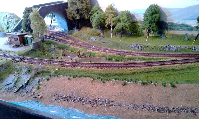
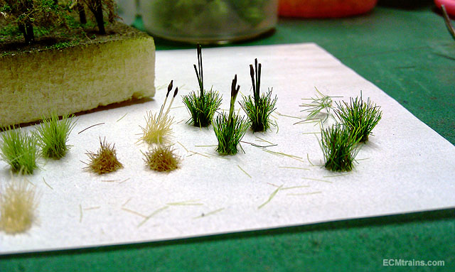
Thanks chaps This is what we were doing yesterday on the layout, sticking down these little bits 2 nights a harvesting. The Bulrush! 6mm static grass tuft with bristles from a cement brush stuck in, then painted green with a thick blob of brown at the top. The Wild Shrubs! the same bristles glued in clumps, bent over and painted, fine wool is draped over some, flock is added, and all glued down with Mod Podge glue spray. Eoin
-
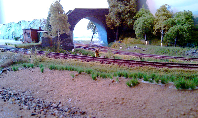
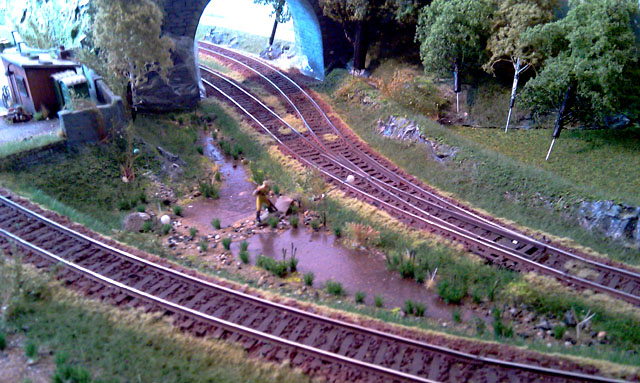
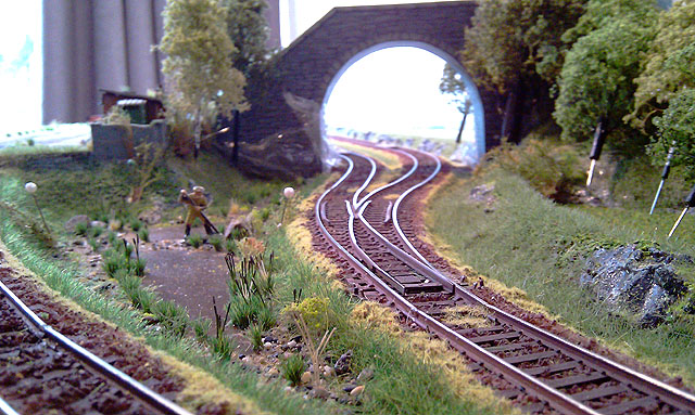
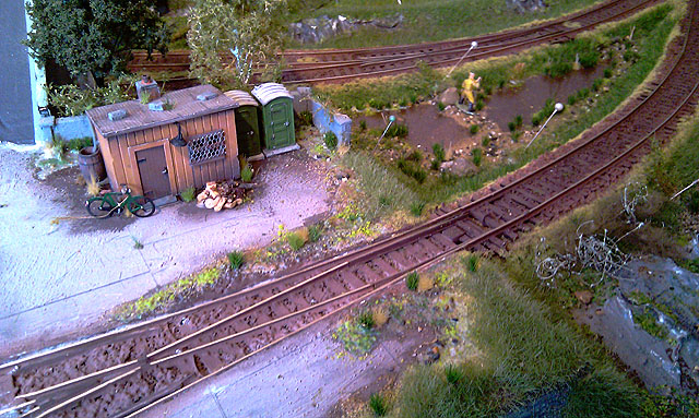
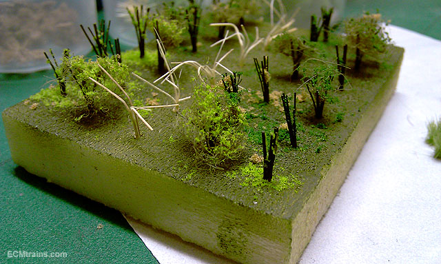
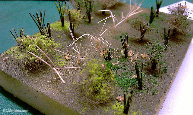
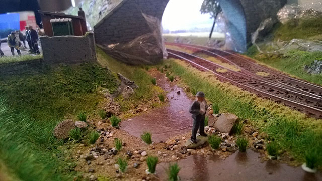
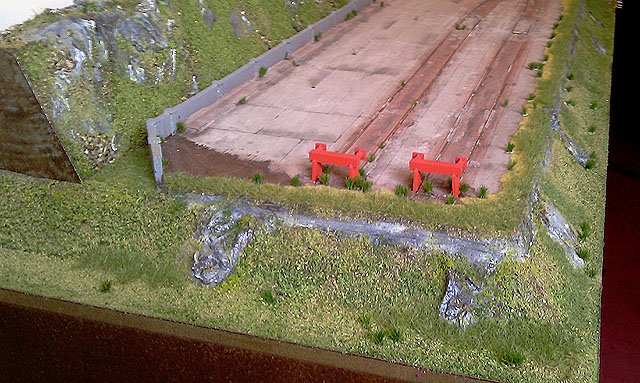
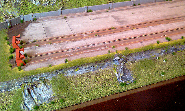
Hi Here are a few shots taken by CM after some work done yesterday CM & Eoin
-
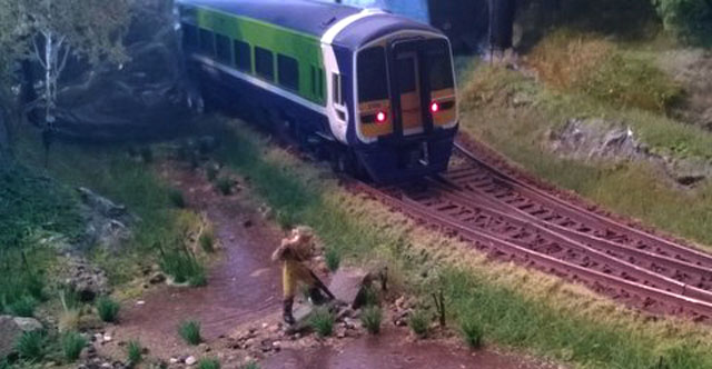
Hi All CM sent me a few photos this morning with captions... "Weeding" "I don't know what the guy is doing; should I ask?" CM & Eoin
-
Hi Friday again! Here are a few shots of the first fine detail layer going down- contrasting grass tufts and the start of the reeds in the Breeches. We are very happy with how the Breeches is panning out, some Bulrushes in next and its almost done. Also some masking of the transition line at the weed sprayed grass is needed, the contrast is to much with the green grass- brambles n flock should do the trick.... Eoin
-
Hi Kirley Oh that's nice, though we cant be leaving her in that orange miniskirt and nought covering up her legs!! better get back to those patterns I think.... Eoin