-
Posts
4,878 -
Joined
-
Last visited
-
Days Won
119
Content Type
Profiles
Forums
Events
Gallery
Everything posted by Mayner
-
https://maps.google.com/?ll=45.38879,-122.93210&z=19&t=h watch out for Big Foot and the Grizzly Bar
-
Some playing around with the video function and editor. Imagine its 1958 a group of railfans have decided to explore and chase trains on the relatively undocumented western extension of the Arigna Tramway. Starting out at Boyle the group chase a mixed train to a crossing point with a coal special filming the arrival of the mixed and departure of the coal train with some panned shots on a roadside tramway section. 6T on the roadside section with the 12:30 Boyle-Ballinamore mixed. 6T arriving at Keadue, 3T waiting with a coalie. 3T departing. 3T on roadside section All I need to figure out is how to improve the photo editing and add realistic sound and smoke effects
-
I agree Courtmacsharry definitely deserves the Dave Holman treatment with a little help from Glenderg! Apart from lifting the track little seems to have changed in the 50 odd years since closure http://eiretrains.com/Photo_Gallery/Railway%20Stations%20C/Courtmacsherry/IrishRailwayStations.html I looked seriously at modelling the T&C in 7mm as nearly all the locos and shortie bogie coaches are available from Alphagraphix, but decided to stick with 4mm. The T&C was probably the nearest thing in Ireland to classic Light Railways like the Colonel Stephens lines, with its odd locomotive collection and wooden and corrugated iron buildings. While a simple light railway it could get surprisingly busy with double headed seaside excursions from Cork and heavy beet and cattle traffic from Timoleague.
-
I got the horsehair along with some scatter material from International Models/Anita Décor at Warley about 10 years ago, and finally got around to using it unaware that its difficult to find. I decided on a mixture of low hedging and post and wire fence in the foreground, so you can still see the road and the trains. I used Woodland Scenics "fine leaf foliage" a natural product glued on top of the horsehair to represent the hedging & applied some extra ground cover to disguise the gap between the fascia and the edge of the scenery. The gate posts are stripwood painted with Humbrol acrylic paint, the post and wire fencing uses Slaters plastic posts and stripped down hook up wire. https://slatersplastikard.com/assets/pdfs/FencingFlyer.pdf. I will probably use the Slaters posts with plastic rodding rather than wire for fencing the line through the cutting around to the loco shed. Not quite stockproof fence with typical Irish field gate. A couple of railway enthusiast cars parked awaiting a photo of the afternoon mixed? The Children of Lir? and a couple of ducks. Swimming in "realistic water" nothing much for a swan or duck to eat or drink. I use 3x1" pine for the baseboard framing with the track and road on 12mm mdf, the framing is notched out locally in two places for the river/lake bed in 6mm mdf. The fascia covers up most of the skulduggery. Ford Prefect waits at the town gates. I finally got around to completing the roadway at the level crossing. I had put off this job for quite a while, the Bemo flexible track used is quite delicate and managed to pull one of the rails out of its fixings and I did not fancy replacing the panel back to the next joint on the station side of the crossing. In the end the track was quickly repaired by soldering in a copper clad sleeper and I completed the roadway across the crossing with strip-wood sleepers stained to look like creosote. The roadway was then coated with pva and a dark Woodlands Scenics fine scatter coat sprinkled on, a cold version of tar and chips, this seems to have matched up nicely with the entrance to the goods yard and loading bank. The p.w. gang is preparing to do some spot re-sleepering and swap out worn rail with sleepers and rail stored by the crossing, the County Council has still to provide footpaths and tar the road past the houses to the station. I badly need some 1950s era signs for the buildings around the station area and tramway. The crossing gates are from the Wills scenic series and fairly typical of CIE gates up to the boom era. The C&L level crossings were pretty inconsistent with targets and lamps, some had targets some had lamps. This end of the layout still needs a little thought about hiding/disguising the hole in the backscene, Presently there is no room for expansion as this end of the layout projects into a window and across our cats' day bed.
-
Most of the smaller items would have been loaded/unloaded by hand most trucks doing local deliveries had a helper to assist with the loading unloading. Most goods yards and some goods sheds had hand operated cranes for unloading large items like farm machinery and containers. Coles cranes similar to the Corgi model were a popular 60s era railway and steelyard crane, one was parked up for many years in Mullingar goods yard. https://www.corgi.co.uk/shop/trackside/dg226000-coles-argus-6-ton-crane-yellow/
-
Sounds suspiciously like Ockie our black-short hair domestic who dares the train to run her down.
-
That particular model of Leyland Comet truck were fairly common around Dublin in the early 60s. Moracrete used a fleet of Leyland Comet trucks sometimes with drawbar trailers for delivering blocks, paving slabs and concrete pipes from its works on the old Dolphins Barn brickworks site, on the Crumlin Road.
-
Several European manufacturers tried British outline HO the Fleischmann Warship diesel and Bullied coaches http://www.ehattons.com/17085/Fleischmann_4247_Class_42_Warship_diesel_in_BR_blue/StockDetail.aspx. were probably among the best. During the 1950s & 60s British Trix hovered between HO & OO. Their final models released in the late 60s including Gresley A3 & A4Pacifics, BRT Scottish Whiskey grain wagons and a Trans-Pennine Intercity DMU set were ahead of then current British RTR. Some of the older locos, the coaches and the rest of the wagon range appeared to be to an odd scale of 3.85mm-Foot literally half way between HO & OO.
-
For a minute I had visions of an American lumber company like Georgia Pacific or Weyerhaeuser running its own logging trains in Ireland with Shays, Heislers and end cab switchers like the good ol USA
-
I would imagine the 450 Class with its recessed doorways would be "challenging", the 70 Class might be a better starting point http://www.worsleyworks.co.uk/Image-Pages/Image_4mm_Class70.htm. Colum Flannagan has turned out some very nice models of UTA & NIR stock using Worsley Works overlays on plastic rtr bodies.
-
fair play for taking the bull by the horns looks really good.
-
Its getting embarrassing this I have been dragging this thread out for so long I decided to finish the F & the J26 to start clearing a backlog of unfinished projects before starting a new layout, but just seem to drag the whole thing out even longer. Externally the F Class is starting to look the part, though it needs number and makers plates, couplers and another coat of paint before weathering. I chickened out on working headlights and did not realise the chopper coupler was upside down. The nearest 9mm group run DCC so there is a decoder to think about. Probably Cristal Clear for the headlamp. The cow catcher also acts as a shunter's platform, need a weather beaten figure in a slouch hat, dark shirt or singlet and shorts sitting on the buffer beam smoking a Woodbine or roll your own. I also chickened out of modelling the various electrical conduits and wiring between the turbo generator and the headlights. The cab interior needs work I first lost the reversing lever, then found it and lost the brake lever. The interior is woefully tight to fit the various castings and a crew. There is some metal work to be done inside the bunker before I add coal. Completion of the J26 now seems to be on standby pending the completion of a couple of 650 Class 2-4-0s and starting work on the layout. Detail wise and mechanically the engine is basically complete with a replacement set of coupling rods ready, just electrical pick-ups to sort out.
-
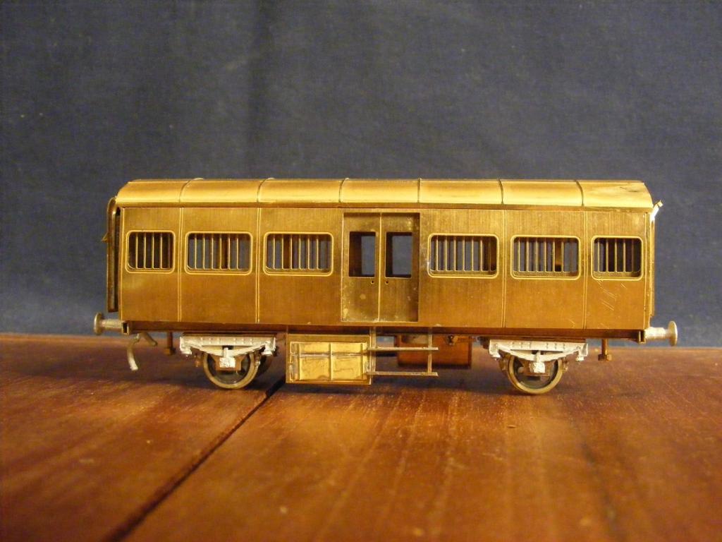
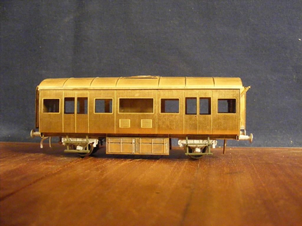
I am now taking orders for both the Heating & Luggage (hot water bottle) and Hooded van (Luggage Van), please send me a PM if interested. I will be in touch with anyone who has already placed and order or expressed an interest. Kits are designed for OO or 21mm gauge and are supplied with RP25 profile OO Gauge wheelset compatible with Hornby, Bachmann, most modern track systems. The vans are priced at £55 with postage & packing to be confirmed. The body work is brass with a simple slot and tab & fold up assembly suitable for gluing, though I strongly recommend solder for securing the sides to the ends and assembling the corridor connections (gangways). The whitemetal detail castings include authentic CIE Bredin Pattern buffers, vacuum cylinders, vacuum and steam heating pipes all courtesy of SSM together with a representation of the distinctive spring/damper roller bearing axlebox arrangement used with these wagons, vans. The first batch of kits to fill existing enquiries/orders should be available Mid-November with a second batch February 2013. Hooded Van Tin Van
-
Some SD45s and other 6 axle power have gone to short lines and regionals in North Dakota for working shuttle elevator and coal trains. The DMVW operates an interesting mix of leased units including some ex Canadian National comfort cabbed GP40-2, WC SD45. The RRVW operates an unusual fleet of ex-Burlington Caterpillar powered GP20s they look like pure bread EMDs but can put out clag like an Alco! [video=youtube;Awa3Oam4K-g]http://www.youtube.com/watch?v=Awa3Oam4K-g http://www.youtube.com/watch?v=3EUVOSq5UeE
-
Many of the earlier road switchers like the Alco RS2 & 3 models and EMD GP7 were set up to run long hood forward this was as much to do with crash protection as tradition. Funnily enough Kiwirail found that drivers would sometimes turn a double cabbed loco if a wye or turning triangle is available rather than change ends. This happened at one particular terminal where turn-round time was tight and did not give enough time on a cold winter night to adequately heat the second cab before departure. Basically after several hours on the road, drivers did not like leaving a nice warm cab, to cart their gear to the other end and face problems with de-misting the windscreen and warming up the cab on the return journey. The American export locos are very close in detail to their US cousins, in New Zealand most locos were basically scaled down American road switchers, the 645 engine locos are on the way out mainly because of age and poor fuel economy, the GE U Boats 40 years on still highly regarded for their fuel economy, smooth riding and low speed hauling ability.
-
The loco can be built in OO or 21mm assembling a rigid OO chassis is fairly simple and she should be fit to go round 2' radius curves. I will certainly look at doing a small batch in OO Gauge rtr.
-
Marcway also do a plastic sleepered OO Gauge chaired bullhead flexible track under the Scaleway label http://www.marcway.net/smp.php which is fully compatible with their OO gauge points. The flexible track looks better is probably easier to lay and definitely easier to ballast than Peco and is typical of main line track in the UK and Ireland up to the widespread use of concrete sleepers & CWR. The lighter rail section should not be an issue unless you use old Triang or Lima locos and stock, in which case its better to upgrade with better quality wheel sets that don't loose their plating and collect dirt. Code 100 track is probably on its way out, over 20 years ago Peco introduced its Code 75 flatbottom system more recently Peco and Atlas have gone head to head developing competing Code 82 track systems for the American market.
-
Most lasted to the late 50s with 6 surviving into the early 60s. They seem to have worked passenger and mail trains on the Sligo and Mayo lines, Dublin-Bray suburban trains (both routes) and Wexford Mail trains until replaced by diesel railcars/locomotives.
-
Great work the loco and her load in the heading photo certainly looks like its straight out of one of one of Neil Sprinks' books on the SLNCR. Vans of bagged cement, ale, cigarettes and Belfast linen for Sligo with a couple of empty cattle wagons at the tail end for Collooney. I don't think the difference in size between the Alphagraphix and scratch built wagons is too noticeable, the GNR vans were to a more recent design than the SLNCR vans and may have been slightly larger. if you are looking at the 1950s period its worth considering the Parkside BR Plysided Van which is very close to the last batch of GNR bagged cement wagons and a good basis for the standard CIE H van. Besides traffic from the GNR to Sligo the SLNCR seems to have conveyed traffic from CIE into Northern Ireland and possibly Donegal, one of the photos in SLNCR an Irish Railway Album is a well loaded afternoon Enniskillen-Sligo goods including a solid cut of 6 CIE H vans towards the rear of the train.
-
Some photos of the build of the study models for the ex-MGWR 2-4-0, this is basically to see if the model is buildable. The basic assembly of the platework is complete, the boiler fittings are just plonked on for general effect, some modifications are needed before the kit is released. The model is assembled in OO with Romford wheels resulting in the wheels being inside the boiler/firebox shell. There was a mix up at the engravers the locos ended up in nickel silver, the tenders brass. 650 Class late MGWR early GSR condition, superheater round top boiler, round canopy cab, tender coal rails. These cabs were used as a replacement for the "Flyaway" cabs on the 2-4-0s and some 0-6-0 but were phased out during the 1930s, they were low (a source of staff head injuries) and gave poor protection from the weather. 650 Class late GSR condition superheated round top boiler, Inchacore cab with round spectacle plates. The GSR replaced the canopy and remaining "Flyaway" cabs with what was basically a standard Inchacore pattern and replaced the cast iron chimneys with a standard Inchacore "built up" variety. Close up of the loco showing cab and smokebox riveting. At this stage its difficult to predict the probable cost or release date, but I would expect Summer/Autumn 2014.
-
The layout slipped back into a bit of a hiatus, I am not sure if it was the winter blues or I hadn't figured out how to deal with the near side of the road. Between the combination of eye level viewing and scenery in the foreground its easy to block out the view of the trains and road vehicles on the tramway. The field boundary will be marked by a combination of low hedgerows and wire fencing, 3T on the Arigna Tramway or Tralee and Dingle That combination of narrow country roads, wild hedges, distinctive farm gates and regional variation in landscape between different parts of the UK and Ireland is difficult for a modeller to capture and can make a layout or a model really stand out. Mid-Wales, the Home Counties and the Yorkshire Dales are distinctly different in terms of their landscape, railways, architecture so why not take the same approach to an Irish layout.
-
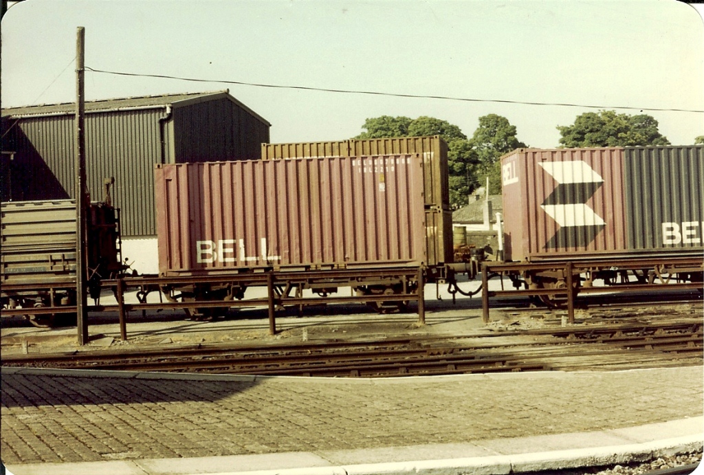
I think a few flats with Bell or British Rail Freightliner containers & Guinness kegs would not look out of place in the consist of your loose coupled Cork-Waterford goods. Improving train payload and better stability at speed may have been one of the main factors in phasing out the 4w flats which were eventually down graded from 50 to 35mph max. The bagged cement and beet doubles seem to have been converted form flats originally used in fertiliser and keg traffic. 4w flats still appeared in container traffic into the 90s mostly coal, oil and grain and mixed consists with keg, cement, oil, tar and container traffic over the Mayo & Sligo roads were not unknown.
-
Not quite desktop 3D printing but a good indication of the probable direction of the hobby. Finished and work in progress. A local designer is using a bureau to produce wagons, the bodies and roof are basically printed in one piece with a separate floor and chassis, the only metal parts are wheels bearings, couplings and brake levers. Finished sheep wagon complete with sheep! The models are printed in a nylon material which is very strong and flexible (Shapeways WSF) the slightly pitted surface finish of this material does not seem to have been too much of an issue in the slightly larger scale. Fully detailed underframe featuring airbrake triple valve, piping and linkages. Costwise its a bit scary around $4-500 for the parts to produce the sheep wagon(incl sheep), but would result in a major saving in time over scratchbuiding or a conventional kitbuilding once the 3D modelling was complete.
-
The plot thickens I have a LGRP 1930s photo of a similar wagon 10567 with the number plate in the same position as the Mullingar wagon. It could be one of a batch of wagons ordered by from Metropolitan in 1920, the GSWR supplied of these 20 wagons at cost price to the CBSCR. The Mullingar wagon may have been used for transporting railcar parts between Fairview and Inchacore, the wagon in the LGRP has an interesting load a pair of steam locomotive wheelsets.
-
The length of container is governed by the load. 30 & 40' containers are used mainly for light bulky items manufactured goods and imports, 20' for heavy dense cargo, commodities such as meat, dairy goods, and bulk cargo liquid of solid. A lot of the traffic was Irish food exports in 20' containers to the European market, including pasta to Italy. It might be worth looking out for used Hornby or Triang-Hornby freightliner container wagons on E-bay, the wagons would need shortening and possibly lowering but the bogies/trucks are right for the 1st batch of bogie container flats, the containers typical of the transition era.
.png.c363cdf5c3fb7955cd92a55eb6dbbae0.png)


