jhb171achill Posted January 11, 2024 Posted January 11, 2024 On 17/7/2023 at 8:26 PM, Mayner said: The South Eastern does not appear to have had the very low platforms commons on the Cork Line and older parts of the GSWR so coaches with lower footboards may have been un-necessary at least in DSER/GSR/CIE days. The GNR(I) also appear to have fitted (or removed) lower footboards from their 6w and older coaching stock. Indeed! The VERY low ones seem to have been primarily a GSWR thing..... I think Mallow was the last, still like that in early 1980s anyway. 1
David Holman Posted January 11, 2024 Posted January 11, 2024 Oh my. Well done Ken. This is where the 3D thing can be so effective, because you have already done all the hard work. Respect! 1
MauriceJ Posted January 11, 2024 Posted January 11, 2024 Deadly stuff.. This may be relevant here.. I’ve been looking through old photos of the Shillelagh Branch. Came across this photo of Aughrim. Wondering are the 2 wagons on this branch set horse boxes? Cheers https://catalogue.nli.ie/Record/vtls000332959 3 1 1
KMCE Posted January 12, 2024 Author Posted January 12, 2024 Hello MauricJ, Great photo and I would agree that they are two horse boxes, however they are different from the model I have researched thus far. Photos of DWWR / DSER horseboxes are rare despite the RDS sidings clearly on the network and one would expect more photos given its popularity. The NLI photo is excellent and is from the DWWR period as the logos are visible on the semi and mineral wagons - It could also be dated by the oil lamps on the coaches, which means it predates 1885. If the published date of 1865 is to be believed, this was taken not long after the line was opened - the line didn't open to Shillelagh until May 1965. It could be that early as the goods shed has not been built yet (not sure when it was), however the open mineral wagon looks like the 1872 wagon built for carriage of copper ore from the Avoca mines, so perhaps a little later Loco looks like a 2-2-2 WT or a very early 2-4-0T (pity the wall is in the way), but good information nonetheless. Thanks for posting. Ken 7 1
MauriceJ Posted January 13, 2024 Posted January 13, 2024 Hello Ken, Good stuff thank you. I’m now wondering were they Fitzwilliam’s own personal horse boxes, who knows.. Savage models btw. There is another photo in the collection of the church at Annacurragh, about 1.5 Miles from Aughrim towards Shillelagh. The branch visible in the foreground. https://catalogue.nli.ie/Record/vtls000332962 In the Aughrim photo, the start signal at the Shillelagh end of the platform appears “off” also. Pity about the wall for sure. I’m sure there must be more such photos out there somewhere! Cheers Maurice 3
Popular Post KMCE Posted February 4, 2024 Author Popular Post Posted February 4, 2024 Wagon production has continued and given I needed a brake van or similar for the train, I decided to upscale the Cattle Brake. The thought process is to paint this in un-lined coach colour with number and class lettering on the doors - the cattle brakes were initially part of the coaching stock and were only transferred to the wagon stock post 1913, so coach livery will bring a bit of colour to the train. The model was tweaked to make it more accurate for 7mm. The coach without buffers just barely fit on the build plate of the printer which led to its own problems. Not all 3D printing goes to plan, and the supports for the end of the coach were compromised given the size which caused some sagging in the buffer beam. This was replaced by printing a new beam cutting out the misprinted part. Other issues were misprinted brake hangers and some problems with the axleboxes - again some re-printed parts were substituted to make good the problems. Brake hangars have always proved to be a problem with 3D printing as they are quite fragile and prone to breakage so I decided to cut some brass re-inforcing strips which were epoxied to the inside of the hangars which then allowed brake rigging to be installed. The bake rigging is removable which will help with painting and access to wheels as necessary. Following the underbody works, attention turned to the roof and body. I decided to use brass for the roof with 3D printed gas lamps and louvres - this allowed installation of rainstrips and gas pipework by soldering on some brass wire. A chimney was also added to keep the guard warm, but this needs to be tweaked as it's a bit askew. Door handles and grab handles added - I figured as this was a goods type brake, there is a greater chance of drovers and guard climbing aboard from ground level rather that platform, so a longer grab handles was added. This is my interpretation of a cattle brake - sadly no photos and very little information remains, so this is a result of much information gathering and interpolation of other coaches being constructed around the same time. Hopefully it's a reasonable representation. Another wagon added was the early 3-plank mineral wagon from the 1860's. Again this model was tweaked for 7mm and I also updated the buffers to the original style more in keeping with these early wagons. To close out the train I tweaked the gas tank to accept the 3 hook coupling so it can run with the other wagons. All for now - more as time and energy permits. Ken 13 8
David Holman Posted February 4, 2024 Posted February 4, 2024 Fabulous work, Ken. Shows what a great investment you've made in developing your CAD skills. Everything is so neat and clean - well worth the time and effort. 4 1
jhb171achill Posted February 4, 2024 Posted February 4, 2024 3 hours ago, KMCE said: Wagon production has continued and given I needed a brake van or similar for the train, I decided to upscale the Cattle Brake. The thought process is to paint this in un-lined coach colour with number and class lettering on the doors - the cattle brakes were initially part of the coaching stock and were only transferred to the wagon stock post 1913, so coach livery will bring a bit of colour to the train. The model was tweaked to make it more accurate for 7mm. The coach without buffers just barely fit on the build plate of the printer which led to its own problems. Not all 3D printing goes to plan, and the supports for the end of the coach were compromised given the size which caused some sagging in the buffer beam. This was replaced by printing a new beam cutting out the misprinted part. Other issues were misprinted brake hangers and some problems with the axleboxes - again some re-printed parts were substituted to make good the problems. Brake hangars have always proved to be a problem with 3D printing as they are quite fragile and prone to breakage so I decided to cut some brass re-inforcing strips which were epoxied to the inside of the hangars which then allowed brake rigging to be installed. The bake rigging is removable which will help with painting and access to wheels as necessary. Following the underbody works, attention turned to the roof and body. I decided to use brass for the roof with 3D printed gas lamps and louvres - this allowed installation of rainstrips and gas pipework by soldering on some brass wire. A chimney was also added to keep the guard warm, but this needs to be tweaked as it's a bit askew. Door handles and grab handles added - I figured as this was a goods type brake, there is a greater chance of drovers and guard climbing aboard from ground level rather that platform, so a longer grab handles was added. This is my interpretation of a cattle brake - sadly no photos and very little information remains, so this is a result of much information gathering and interpolation of other coaches being constructed around the same time. Hopefully it's a reasonable representation. Another wagon added was the early 3-plank mineral wagon from the 1860's. Again this model was tweaked for 7mm and I also updated the buffers to the original style more in keeping with these early wagons. To close out the train I tweaked the gas tank to accept the 3 hook coupling so it can run with the other wagons. All for now - more as time and energy permits. Ken W O W W O W 1
Tullygrainey Posted February 4, 2024 Posted February 4, 2024 Brilliant stuff Ken. I’ve been drooling over these photos. The 3D prints are wonderfully crisp. 1 1
KMCE Posted February 6, 2024 Author Posted February 6, 2024 On 5/2/2024 at 12:07 AM, WRENNEIRE said: As handy as a small pot..... You can't beat a small pot!! 4 1
KMCE Posted March 2, 2024 Author Posted March 2, 2024 Back to the loco for a spell. Upper body is dominated by the tanks on these locos and they take some time to get right. The kit is designed with both a tank top and tank bottom formers to help form the sides with minimal distortion. Tank side wrapped around the top former. Then fixed to the lower former to help fix the shape. The lower tank former also acts as a means to hold the body down on the chassis, so captive nuts soldered in place. Second tank side added. This kit needed a separate lower trim detail - in the P4 version this detail is part of the side and back folded up. Metal at 7mm is too thick which would have made the corners very difficult to form, so a separate strip provided which is sweated into place. And tanks on the chassis for context. Whilst visually and descriptively this does not appear to be much work, I can assure there is a lot to it, and one of those jobs I'm glad to get done. Can move on with cab and boiler next. Anyway, all for now. More as time and energy permits. Ken 10 1 3
David Holman Posted March 2, 2024 Posted March 2, 2024 Classy. Lovely work, Ken. Can only agree these things require care and patience. 2 1
KMCE Posted March 4, 2024 Author Posted March 4, 2024 Moving along, cab is up next. Cab sides are mated to the bunker rear on the bench and then offered up to the lower tank former and tanks. Forgot to take photos as I was working, so most was assembled before I remembered to take any. Cab front was then dressed with the additional detail. One detail which did not make it through the etching process was the spectacle detail - outer ring was formed but the centre didn't etch out, so I had to use some half round brass to provide the detail. Fiddly to execute, but hopefully in the final kit version, this should only take minutes to sweat them on. These locos also had a distinctive riveted arch over the boiler which is allowed for. Rivets are half etched on the rear of the sheet and need pushing out; given the thickness of metal, I used the rivet punch to complete the job. Same issue with the cab rear for the spectacle plates, but once done the cab rear slides down the etched guides into place for a nice clean fit. Dimensioning of parts in the kit has worked out well for these elements and they have come together quite nicely. All that's left is to add the roof - in this instance I used phosphor bronze wire to create springs in the corners so the roof can be taken off should I want to do any internal detail. Back onto the chassis to get an overall look at how it's coming together. All for now. Ken 10 4
David Holman Posted March 4, 2024 Posted March 4, 2024 I really must try to be neater when soldering. Always great to see skill in action. 2 1
Galteemore Posted March 4, 2024 Posted March 4, 2024 Lovely work Ken. Any chance of a look at the roof springs please? I’ve often pondered such a thing….. 1
KMCE Posted March 4, 2024 Author Posted March 4, 2024 No problem. Quite simple in that there are only 4 wire springs, however the tricky bit is getting them sufficiently tensioned to keep the roof on and centralised. Hope that helps. Ken 7 1 1
Galteemore Posted March 4, 2024 Posted March 4, 2024 Thanks Ken. Tried that in the past and found it tricky - so reassuring that you do too!
KMCE Posted March 4, 2024 Author Posted March 4, 2024 What I find helps is marking the the outline of the cab onto the roof with a felt pen when you're happy with the fit, then scribe in 1mm from that line. These lines act as guides to where to bend the wire & get a rough fit for the roof. You can just make out the scribe marks in the photo above. Ken 1 1
David Holman Posted March 4, 2024 Posted March 4, 2024 Me three! Fitted them to Sir Henry and they still need tweaking. 1 1
Tullygrainey Posted March 4, 2024 Posted March 4, 2024 Beautiful work Ken, and a joy to see. So wonderfully neat - not a trace of solder on the outside! Where can I get a soldering iron like yours? I like the springy wire method for holding the cab roof on. Might be tricky to do but at least it can be fettled to fit. I’ve used a central bolt into a captive nut to do this job but it needs to be planned for well in advance and if you get it wrong it’s hard to fix. The bolt also needs to be hidden under a roof hatch. 2 1
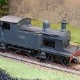
KMCE Posted March 6, 2024 Author Posted March 6, 2024 Following on from the last work, the next phase was boiler and smoke box. Me being me, I once again forgot to take interim pictures - once I get focused on an element, I forget to take photos. What I have got does show the smoke box former and boiler being formed, so I'll have to fill in the gaps with text. Boiler was rolled and the small semi-circular formers and front disc were used to get the shape correct. The etch was to include a forming ring in the Nickel Steel element which slips over the boiler and helps to keep the shape when soldering - this ring also is used as the first step down ring from the smokebox to the boiler, so serves two functions. Sadly this did not etch properly & so I had to make do with what I had. The two semi circular sections help to keep the cut away section to the correct shape - I find the rolling only will not get and keep the shape in this section, so these elements help to keep the shape, but leave clear space for any internal motor & gearbox arrangement. Boiler seam soldered up nicely, but dimension are probably 1mm out as there was a slight gap when fitting the disc; I can change this in the etch for the final version. Smokebox was up next and this was created in the usual fashion of a smokebox former with the outer wrapper sweated on. Alas, this is where the photos stopped. The smokebox wrapper needed to be annealed to soften it as the metal thickness was too much for immediate installation. The design is for the wrapper to sail past the former which creates a pocket to allow the installation of the 3D printed smokebox front. I found this method worked well on the other locos I built and followed the process here. Again some dimensioning issues here; smoke box wrapper was c. 2mm long while the former stands c. 1mm to low. The recess created is also a little too deep, so the smokebox front is packed out with some scrap brass from the fret to get things lining up again. To resolve the heights issues, the former is packed up with an off cut from the etch, while the bottom of the sides have been filed back to fit - not ideal, as this brings the rivets very close to the footplate. All these issues can be picked up during the final design pass for the kit - they are not major issues, but once found it will be good to get them sorted. I had not included any boiler bands in the kit, and not having any 1.5mm strip, I cut strips from spare brass in the kit & made up the bands - quite a bit of work & I think I'll include boiler bands in the etch to make it easier on the next builder. So, bringing it all together with some of the 3D printed parts we get: It has come together quite well even with the few kit issues. These were not major but the did add to the build time whilst workarounds were sought. Looking good so far, but that's the easy bit done - now for the tough bit......all the detailing. I find detailing can take almost as long as the basic build, and while it feels you a working for an age without progress, it does make the difference in developing the model. I'll probably pause the build for now, take a break and work on some other parts of the project. I took a photo of the loco next to @Northroader excellent J15 and was quite surprised at the size difference. I my mind I had always seen the 423 locos as small, but they are of considerable size next to the J15 - no wonder they were so capable and ran on the system almost to the end of steam. Nice comparison. Anyway, all for now. I'm off to work on some other bits for a change. More as time permits. Ken 10 5
Galteemore Posted March 6, 2024 Posted March 6, 2024 Fabulous work Ken - and one’s mind doesn’t necessarily turn to cameras in mid-solder! It’s incredible how ‘big’ a small engine can be. Years ago I had a 7mm G6 which I thought quite small …..until it met a Terrier…. 8 1
David Holman Posted March 6, 2024 Posted March 6, 2024 Another 'Oh my!' from me Ken. The loco looks great and am sure the detailing will gild the lily, as it were. 2 1
KMCE Posted March 8, 2024 Author Posted March 8, 2024 Got some painting done on the wagons. I think in need to tone down the Cattle Brake as it's a bit glossy - perhaps a little matt varnish would help. A touch of bleed through with the black on the corner, but that should clean up easily - the body paint is tough paint (rattle can RAL 3004). Lettering and numbering to follow, but quite pleased how they have turned out. They do take quite a bit of paint given the size - will need to order some more air brush paint! And an overall view; DSER branch train with loco..... Anyway, all for now, and for those going, I'll have this on display in Bray. Ken 12
WRENNEIRE Posted March 9, 2024 Posted March 9, 2024 Anyway, all for now, and for those going, I'll have this on display in Bray. Ken If your let!! 2
Recommended Posts
Create an account or sign in to comment
You need to be a member in order to leave a comment
Create an account
Sign up for a new account in our community. It's easy!
Register a new accountSign in
Already have an account? Sign in here.
Sign In Now