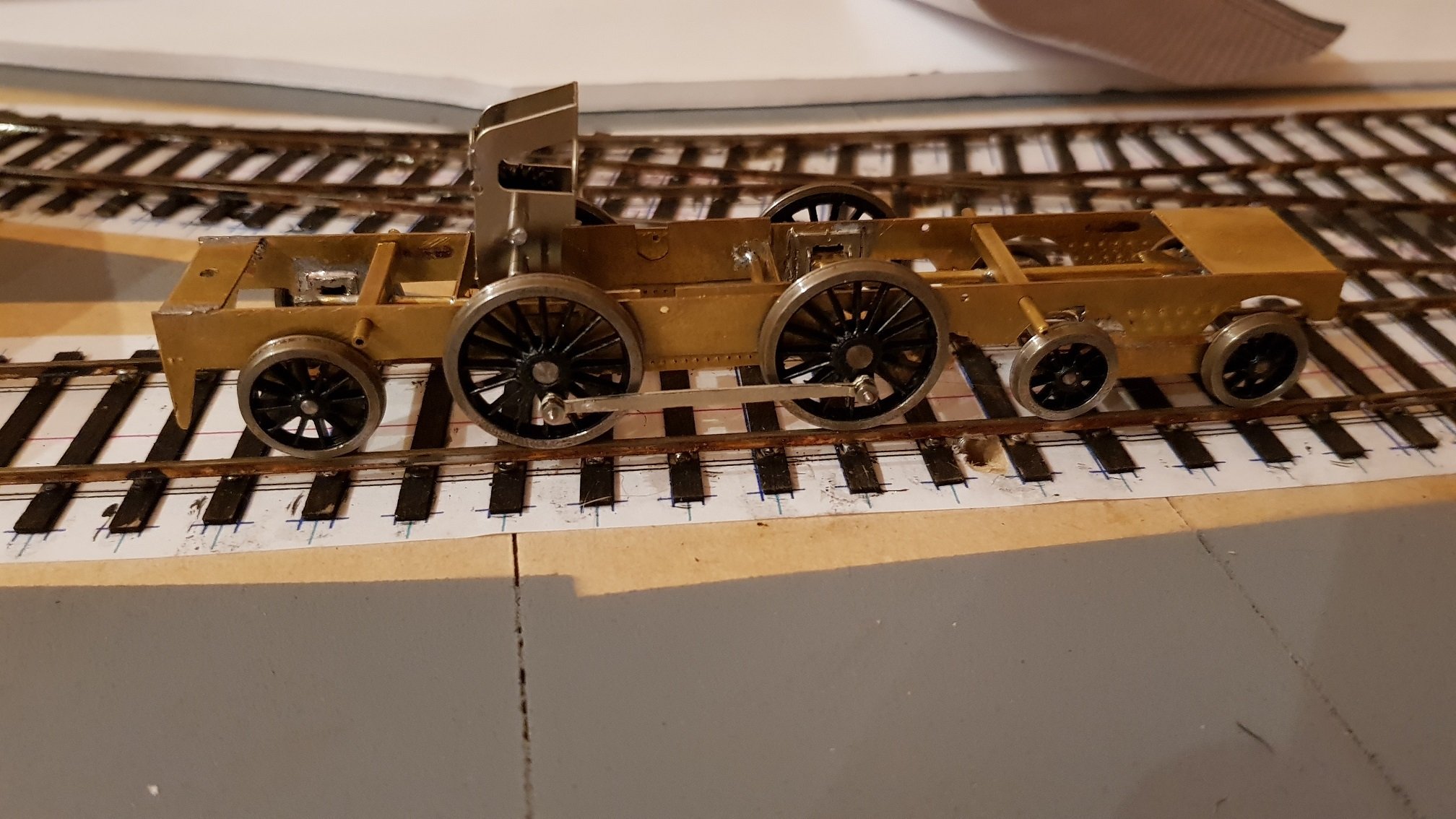
KMCE
-
Posts
540 -
Joined
-
Last visited
-
Days Won
29
Content Type
Profiles
Forums
Events
Gallery
Blogs
Everything posted by KMCE
-
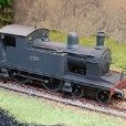
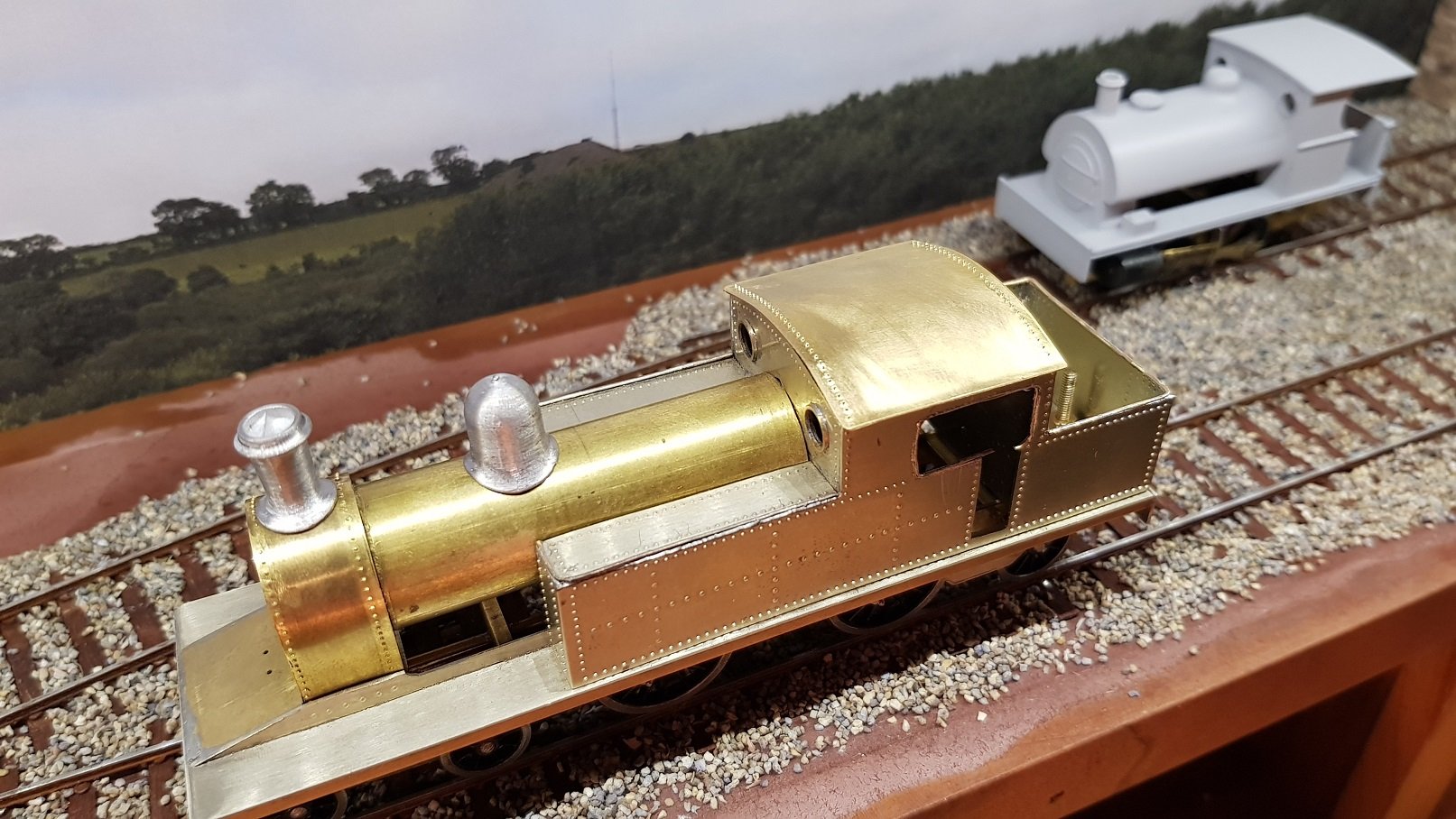
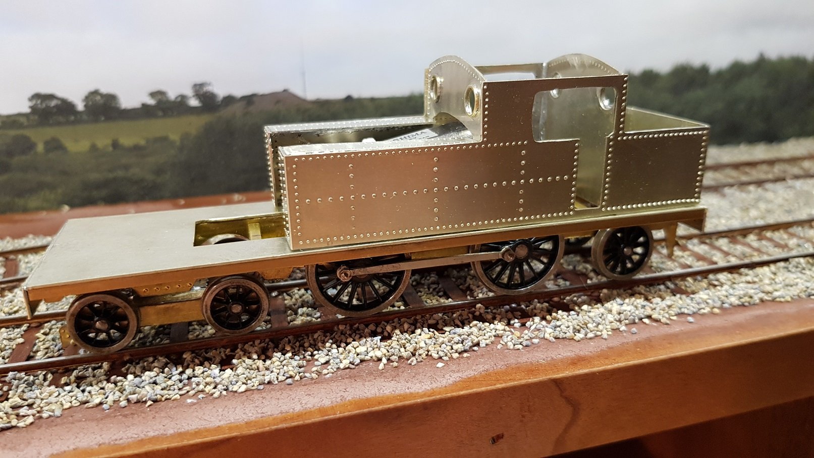
Some more work. Roof was shaped from some brass sheet and rolled into a rough form - this needed fettling to fit the cab curves. Cab sides also needed some fettling to allow roof to sit down properly. Roof is held in place with PB wire tabs - it provides a friction fit so it can be removed if necessary. I'm still debating this - is access really needed when the whole locomotive comes apart quite easily? It is a little difficult to get the roof to sit tightly. Sides were bent up slightly using the folding tool and a line of rivets added front and back. Next up was the interconnector between main and bunker tanks. This is under the footplate and behind the cab steps. Basic construction of which was fixed to the underside of the footplate leaving room for the steps later. So tank connectors and roof on, we get this. I had a smoke stack and dome from another kit which were close to the prototype, so added these. Not entirely happy with the location of the dome - it is a little too far forward when viewed from the side. The safety valve bonnet has not been added yet which may help to reduce that long run of boiler behind the dome. We can deal with that later. One element recommended in the book "Scratch-Building Model Railway Tank Locomotives" by Simon Bolton is the use of half round brass wire to provide finishing details. It's a good idea and looks well in the book. He comments that he would be lost without his half round brass wire.....hmm...I think I'm lost with it!! In principle it is quite a straight forward operation - tin the seam and back of the wire and sweat the two together. In practice, it's a little more difficult to get the lines straight and corners crisp. First attempt on the LHS tank will need to be redone as it is all over the place - later work on the RHS tank, cab openings and bunker are a little better and do help to soften the edges. All part of the learning curve as they say......... However, we are starting to get a smart looking locomotive (even if I do say so myself!) More soon. Ken

-
John, Superb work there - very impressed with the crispness of the etchings and how well they go together. You have me sorely tempted with this one, as I have a soft spot for the 2-4-0 class, both tender and tank. My next build will most likely be a 423 2-4-0T used on the DSER line; hence the earlier query about leaf spring castings. I rather like the bending jig you have for flaring the tender sides - perhaps you may provide some more info? You show rivet details on the smokebox, etc. Are the rivets part of the etching process or do we need to add them ourselves? From your earlier comments regarding the gauge, I assume these can be made up in 21mm? Regards, Ken
-
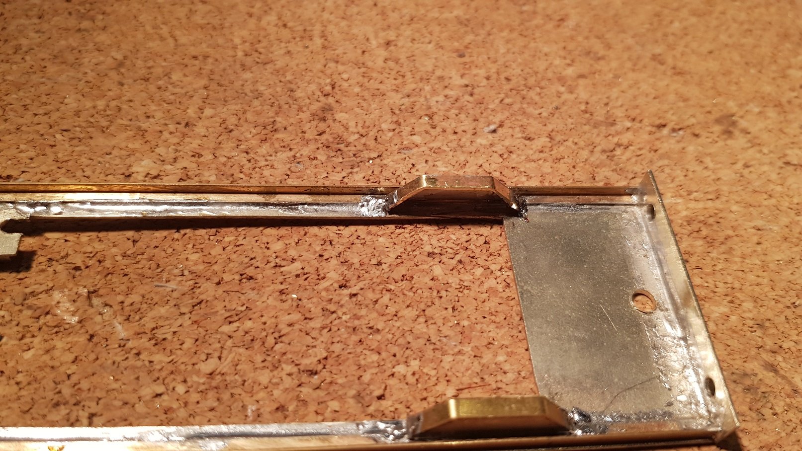
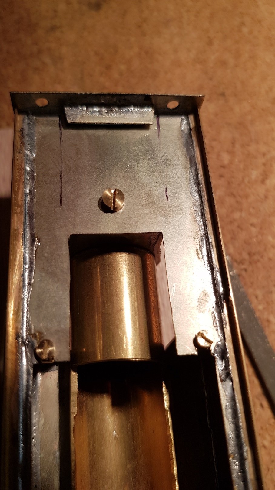
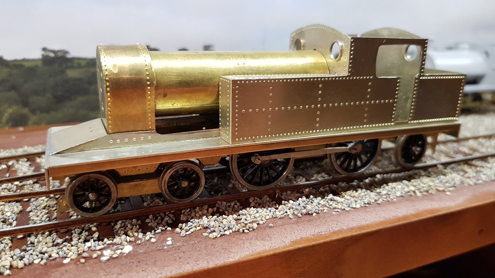
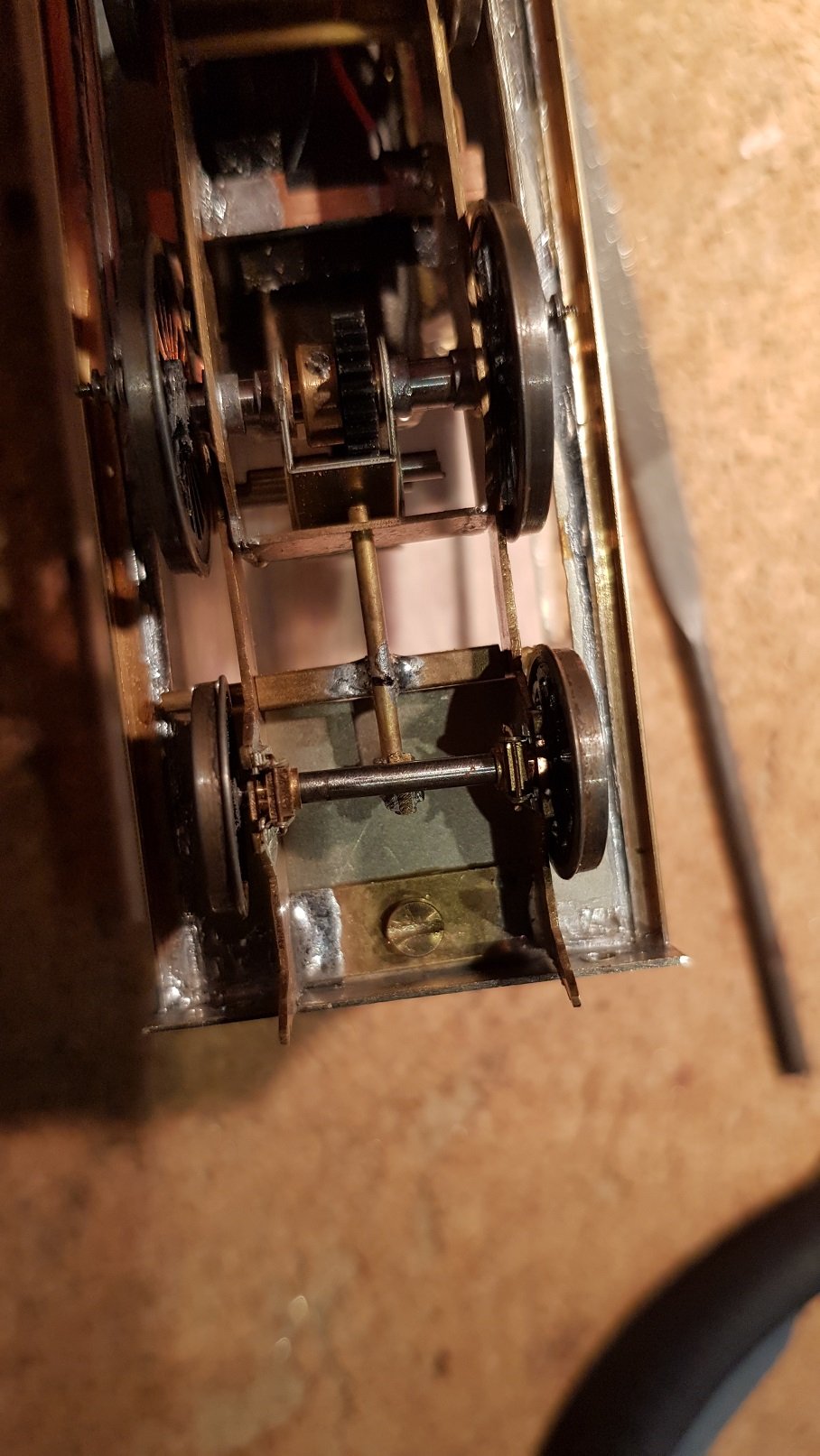
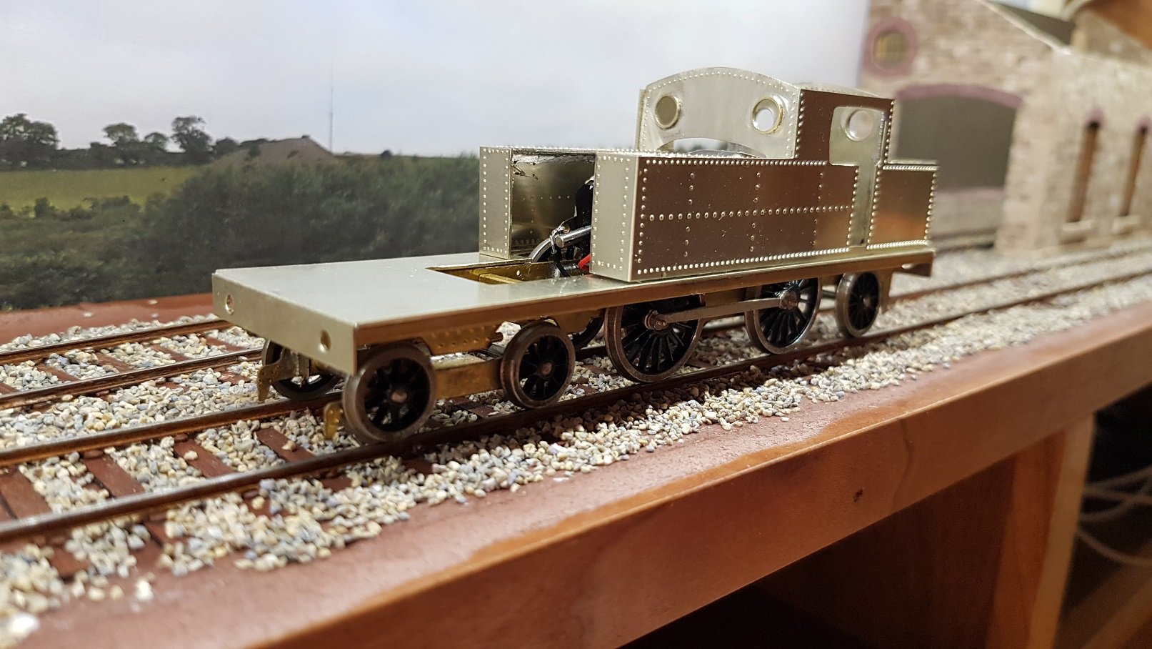
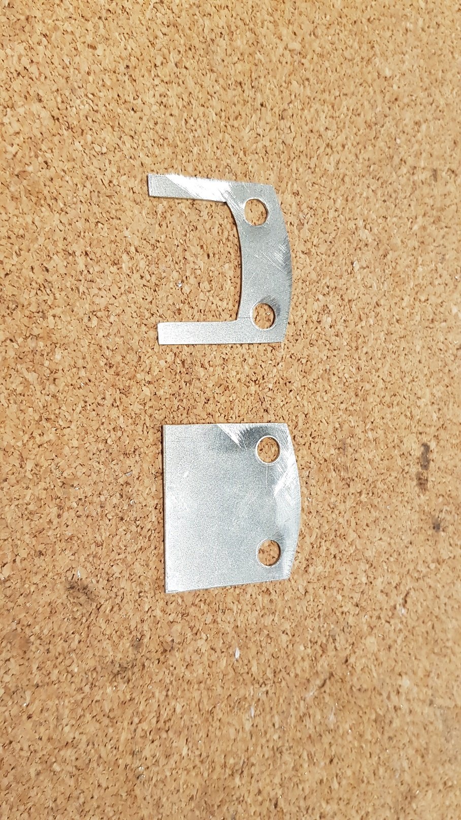
Recent progress - Quite a bit of work, but not much to show compared to before. Boiler, body, footplate and chassis are now fixed. Done in a way to ensure it can can come apart for painting and maintenance. Tab installed at the front and screw through to the bunker holds the chassis. A fixing plate and captive nut was soldered to the base of the smokebox with a bold through the footplate holds the boiler in place at one end, with a nut through the cab front holds the other end. A nut was soldered to the inside front face of the tanks which allows bolts thread thorough from the footplate to hold the tanks down. All good and secure now. Cab front has been soldered onto the cabsides, and the gaps filled to provide a smooth face. Some last tiding up around the opening for the boiler holding bolt will be needed now that all is in its final locations. The front upper frames were made and fixed down either side of the smoke box which finishes the footplate off nicely. The prototypes had a plate with grab handle on it which covers the front of the valves and this was soldered into place. These few items, while taking up most of the evening are starting to finish off the model nicely. So the big question - with the extra weight does it run well. Eh - no, not yet. The weight is transmitted down through the compensation pivot points, but is bearing more on the bogie and trailing wheels, so a little fettling is required to settle the drivers firmly on the track. But we are getting there. Still need to do the bunker tanks, and put in some false tank ends inside the cab. A roof would be nice, so we still have more work to do. More shortly. Ken
-
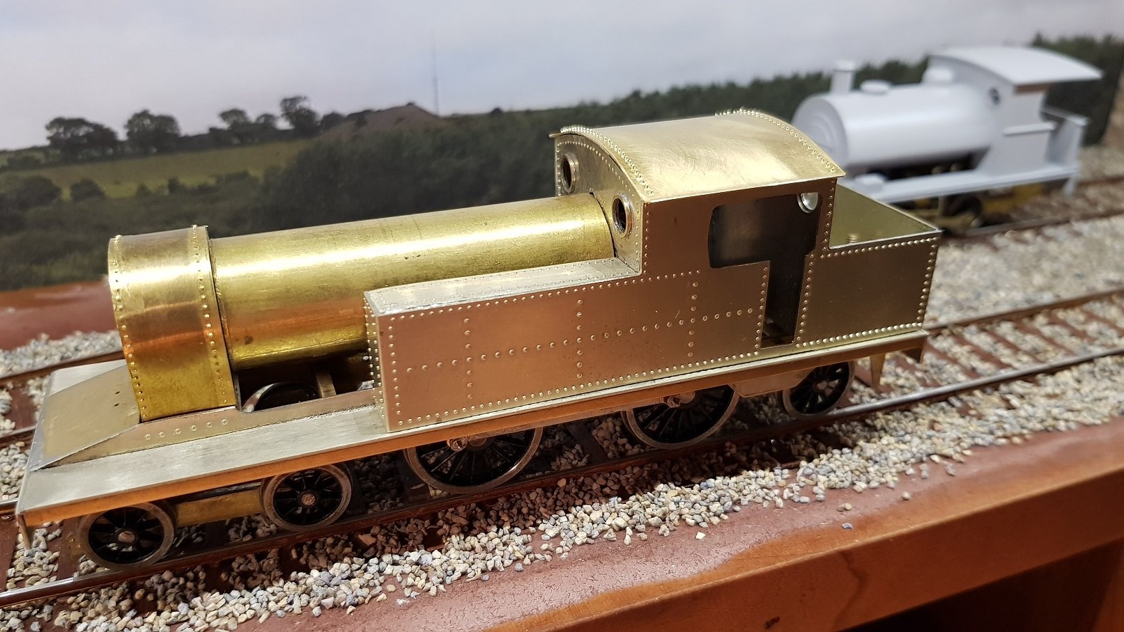
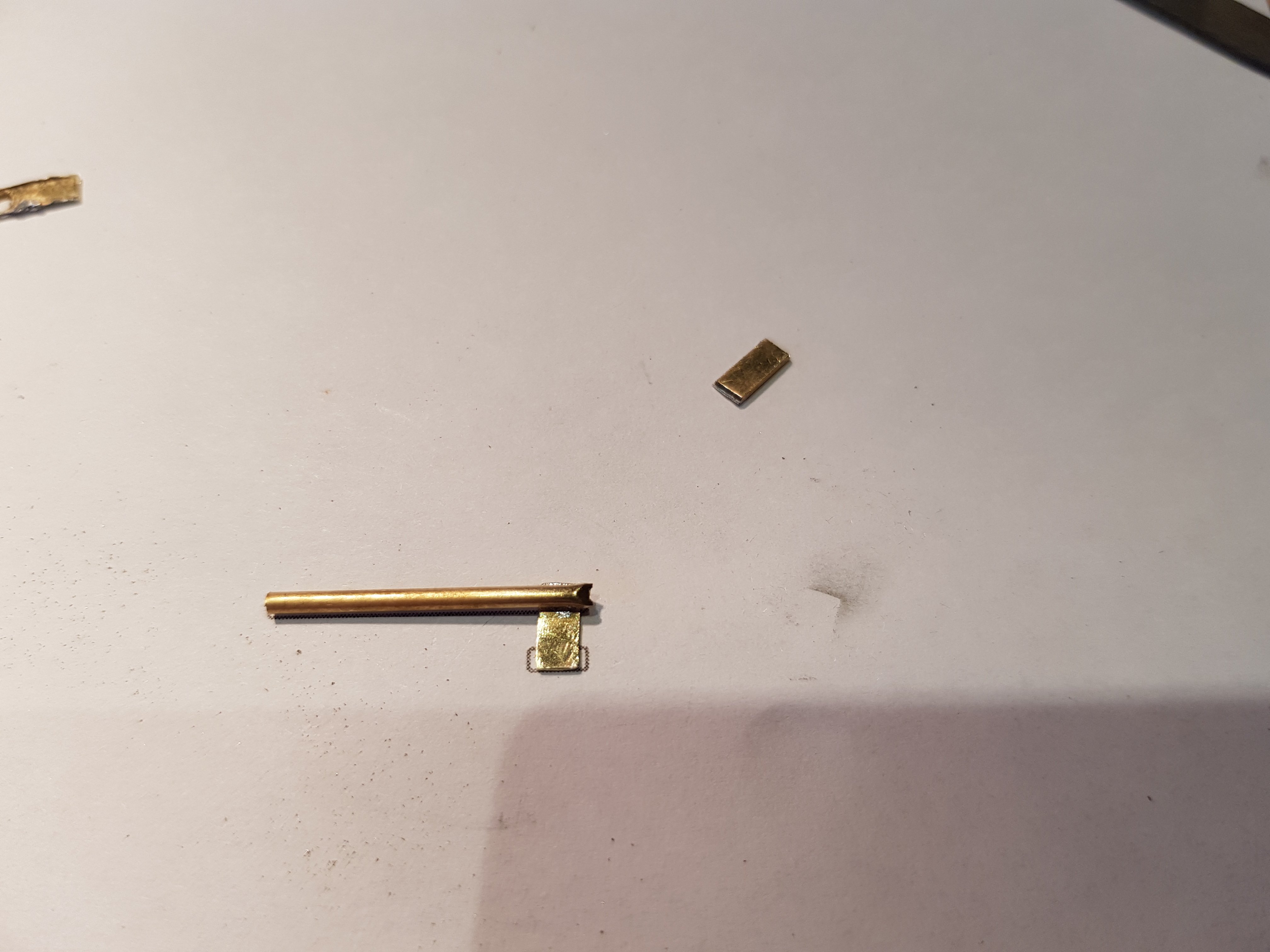
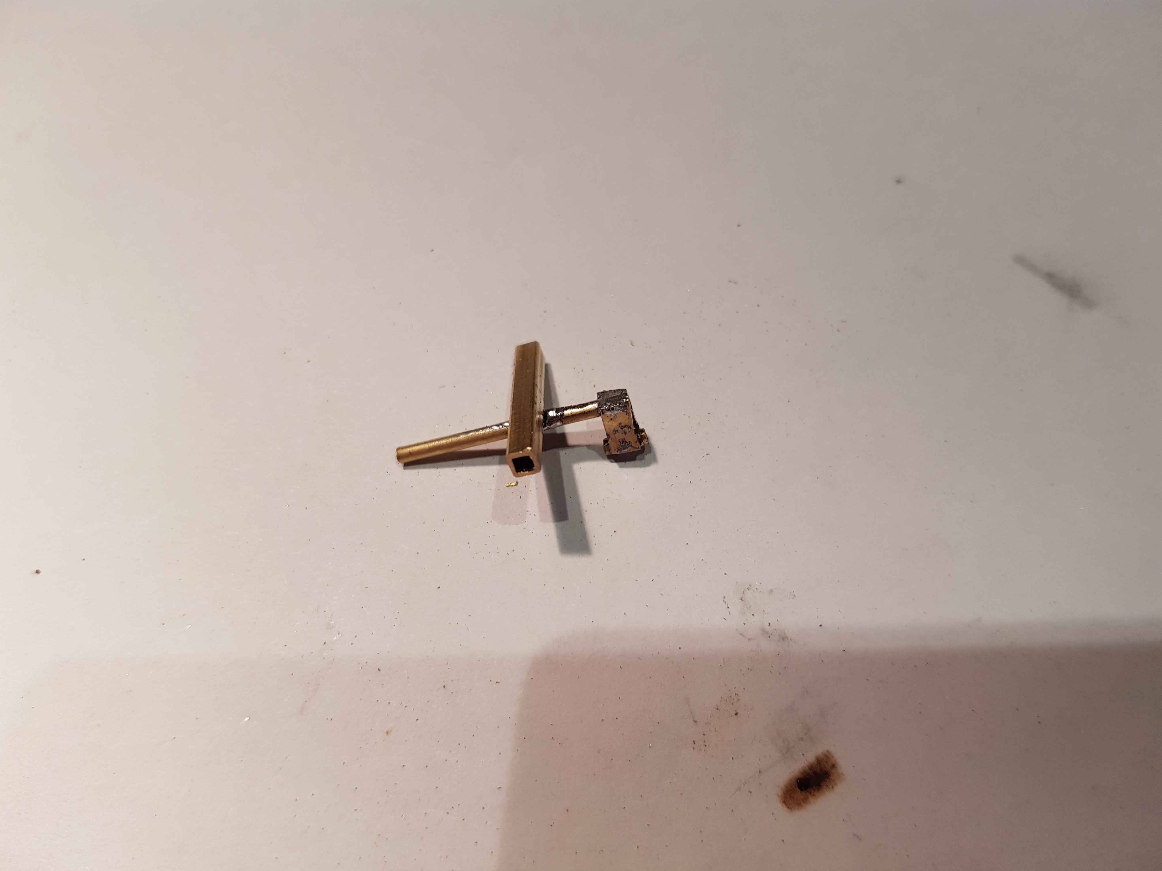
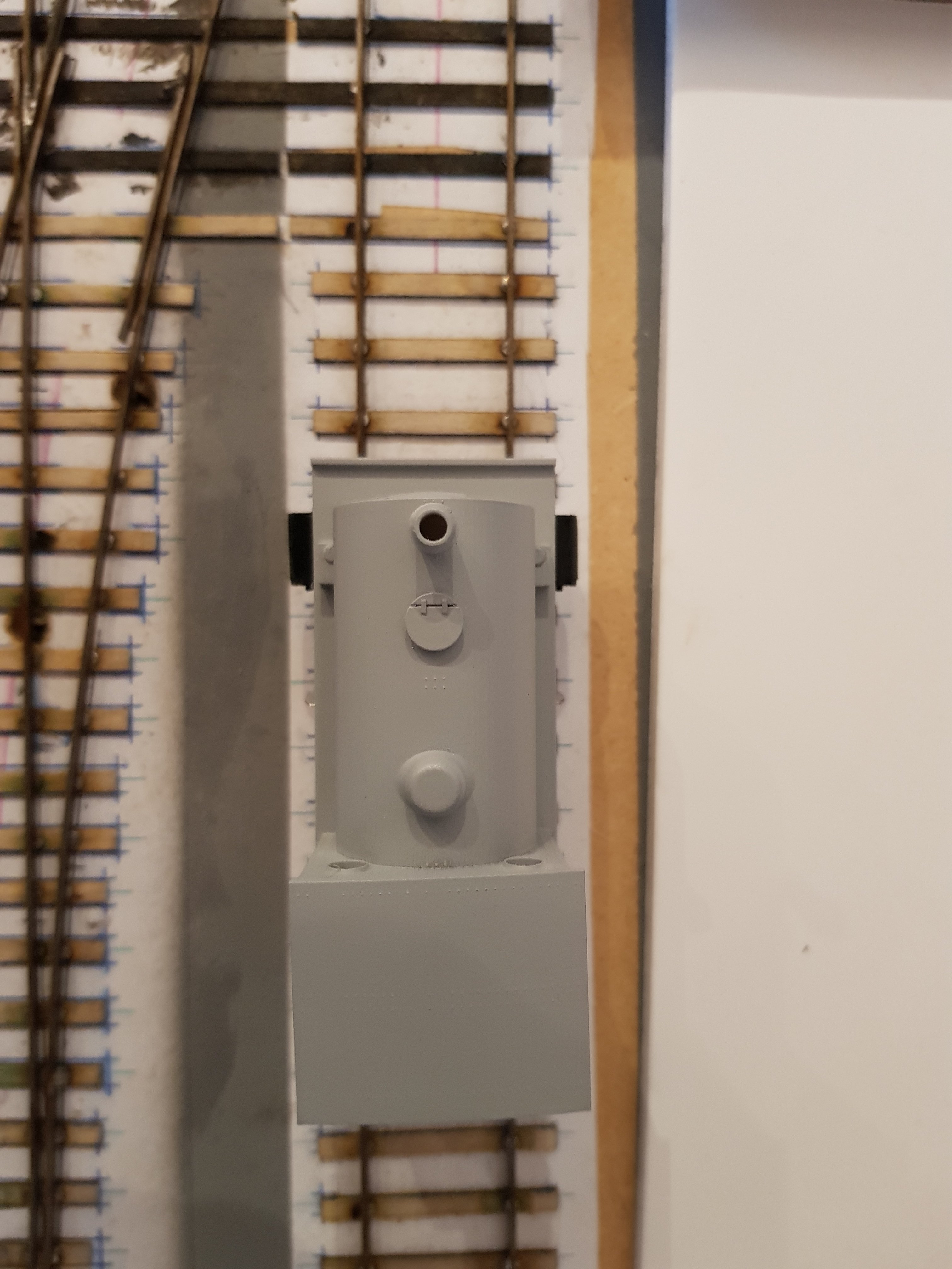
Finally, some round stuff. Got to work on the boiler and smoke box this evening. A spacer was fabricated from some scrap for inserting between the smoke box formers. The captive nut is to allow connection of the boiler and smoke box. Wrapper was fabricated from some 0.3 mm brass and rivets added for detail. It was rolled using tube on the thigh - quite uncomfortable after time, so a general shape was developed and then tacked to the formers. The reverse curve was generated using a tube pressing against the former and then the wrapper was finally soldered in place. The excess front and rear was ground / sanded away to leave a smooth face front and rear. Boiler barrel was formed from some brass tube and an insert with captive bolt was created using threaded rod and a nut. The threaded rod will thread into the captive nut in the smoke box. Once the boiler barrel was tightly connected to the smoke box, it was time to mark and cut away a section of the barrel where the motor is located. This cut was initially a little short, and was catching the spare end of the motor shaft, and rather than cut back to this point, I elected to cut a slot to clear the motor shaft. I may adjust this later if there is a need to fit a fly wheel on the motor shaft. This work takes time as the boiler barrel absorbs quite a bit of heat and it takes much longer than normal to get some proper soldered joints. I needed to up the soldering iron to 400 C to make any reasonable progress. Next thing was to mate the boiler / smoke box to the cab front. The threaded rod soldered to the inside top of the boiler should line up with a hole in the cab front. Yeah, right! The hole / threaded rod combination were about 1mm too far to one side, so the hole needed to be elongated to get the correct fit. Took a bit of fettling, but it's more or less in the correct position now. It's not a big issue, as the nut is inside the cab and will not visible. Finally, try it together with the work already complete, et voila! Now it's starting to look like a locomotive!! More soon.
-
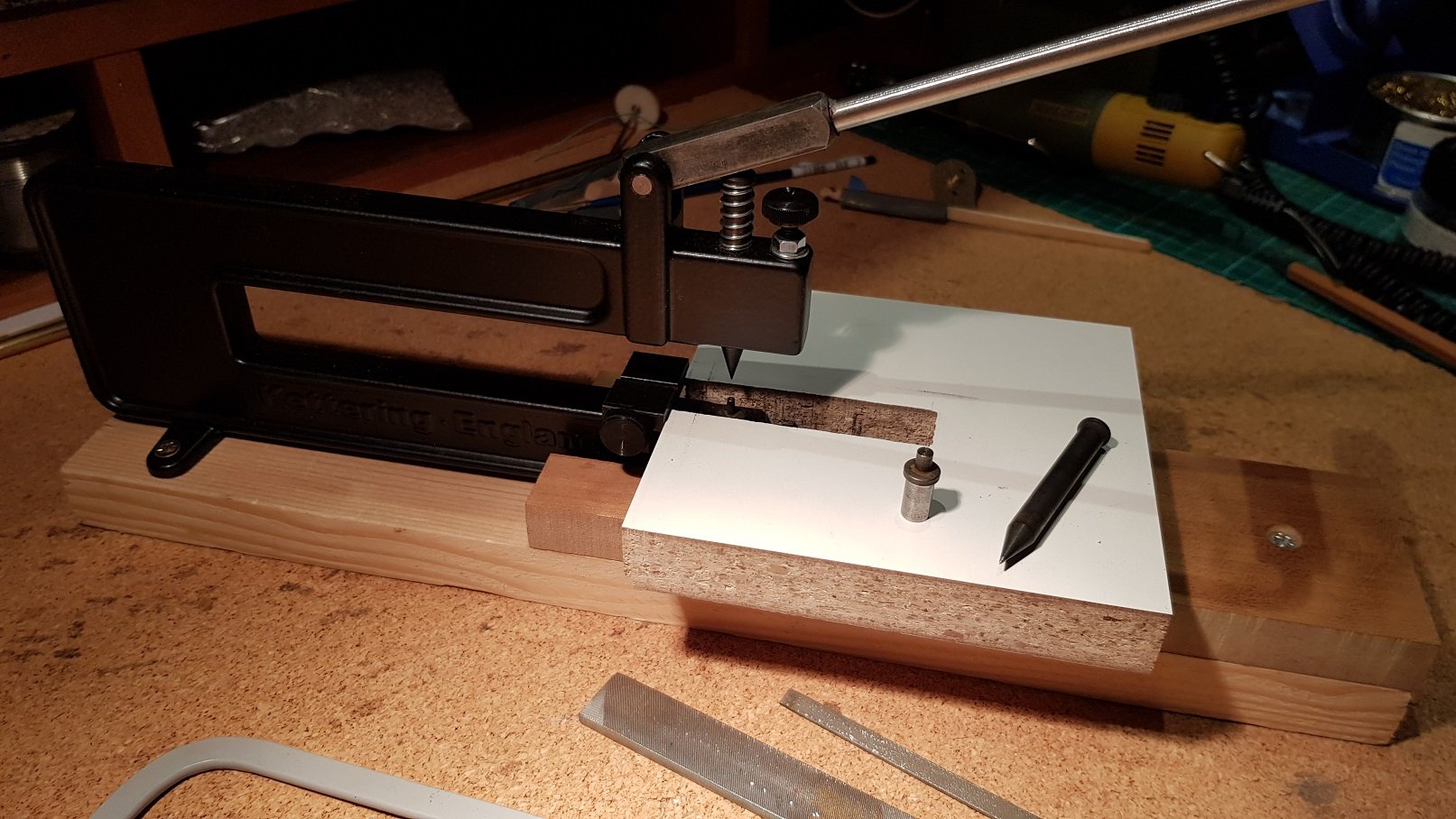
Hello John, Thanks for your comments - much appreciated. As to the questions: For cutting straight lines the following are used depending on material & what's involved Cutting blanks out of the base sheet is with a heavy steel rule and a stanley knife. The sheet is scored multiple times until a faint line is seen on the other side. The piece to be cut off is clamped in a large vice & remaining sheet is bent back and forward to break the joint. The burr created by this needs to be cleaned up with a file. This method is also used to cut straight lines on single sheet smaller pieces, but using a hold and fold tool to clamp the piece. For patterns (tank sides for example), two sheets are lined up and tacked together with solder. I then either mark using a dividers, or if a complex pattern, using a printed template glued on with pritt stick or similar. The scribe mark is better as the metal has a more permanent mark - the paper template has a tendency to get shredded in the cutting an filing process, so lines are not so clear. Straight lines on twin sheets are cut using the piercing saw and then cleaned with the files to get a straight line. The key I have found is to leave enough slack to ensure you don't cross the line, but not too much so you have a load of filing to do. The book I mentioned before recommends the finest of blades for the piercing saw, however I soon got fed up of breaking and replacing blades, so I went for a slightly larger blade, which tracks straighter and is not so brittle. For the rivets I use the Kettering Press which can be bought with different sizes of hammer & anvil for different scales. I got the 0.4mm (OO) and the 0.7mm (O) and use both on the model, as there are clearly larger and smaller rivets on the prototype. I had to make a base, platform and sliding table to hold the work while I press it, as it would be almost impossible to hold small pieces steady enough to get a a reasonable line. the sliding top has a dovetail groove on the underside with two screws fixed in the base below, so slides on the groove without too much lateral movement. The table and base are just made up from scrap timber from the workshop so are not pretty - "form follows function" and all that. To get the straight lines, there is a backstop which helps to keep the rivets in line, and obviously can be set for different depths depending on what you are trying to do. As for the even line, what I found is that when a rivet is punched, the collar on the anvil, acts like a stop (or spacer) and provides a clean evenly space line of rivets. I have found it is not possible to get a tighter set out as the material will not sit properly on the anvil to stamp closer. Wider spacing would need some marks on the material, as there is no indexing facility with this tool Hope that hasn't been too long-winded an answer to the questions and helps. Regrads, Ken
-
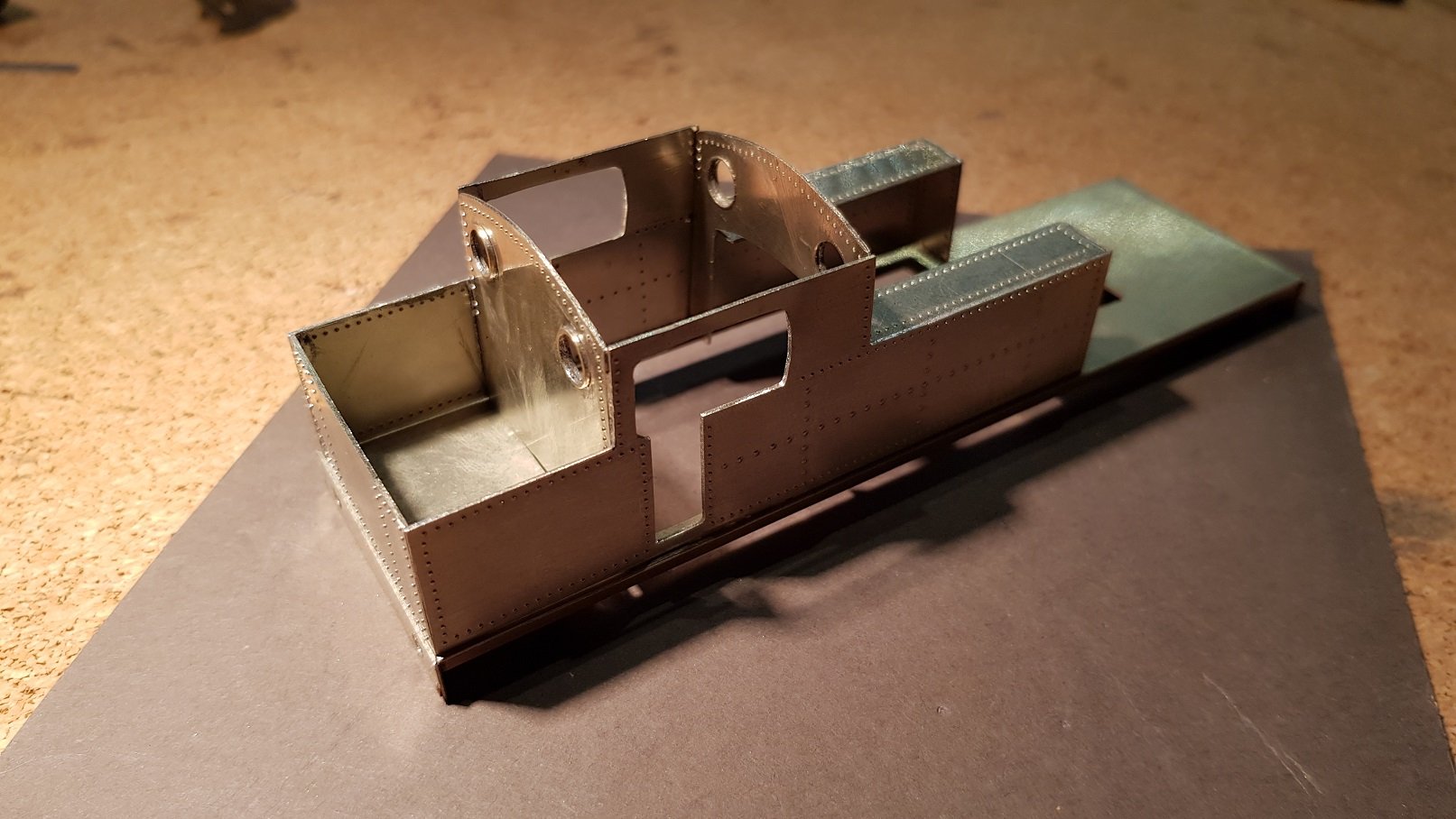
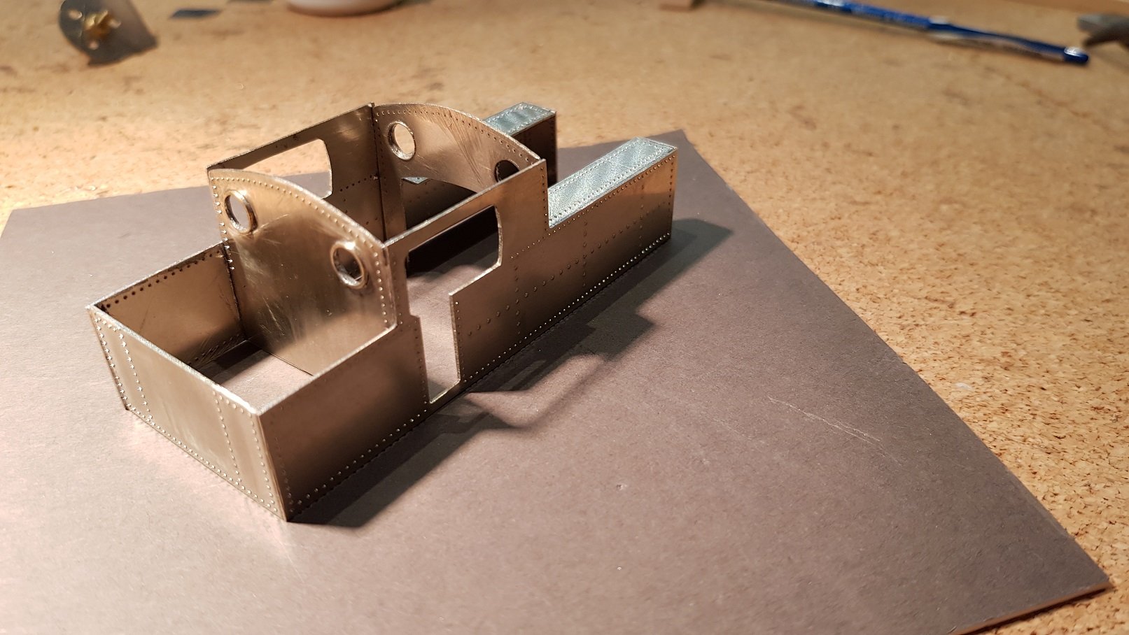
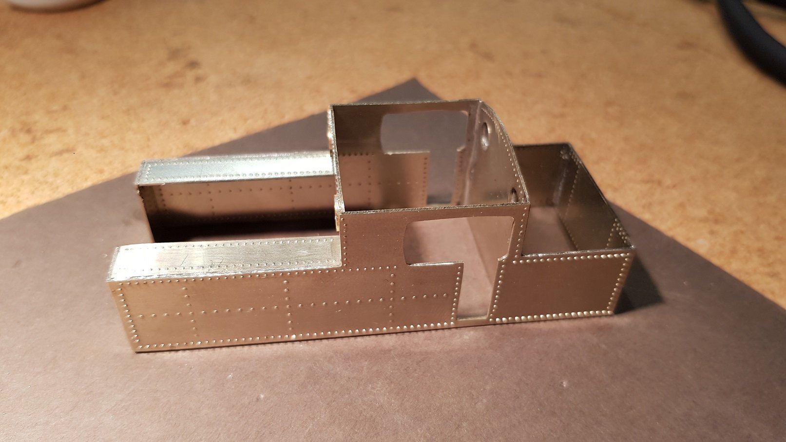
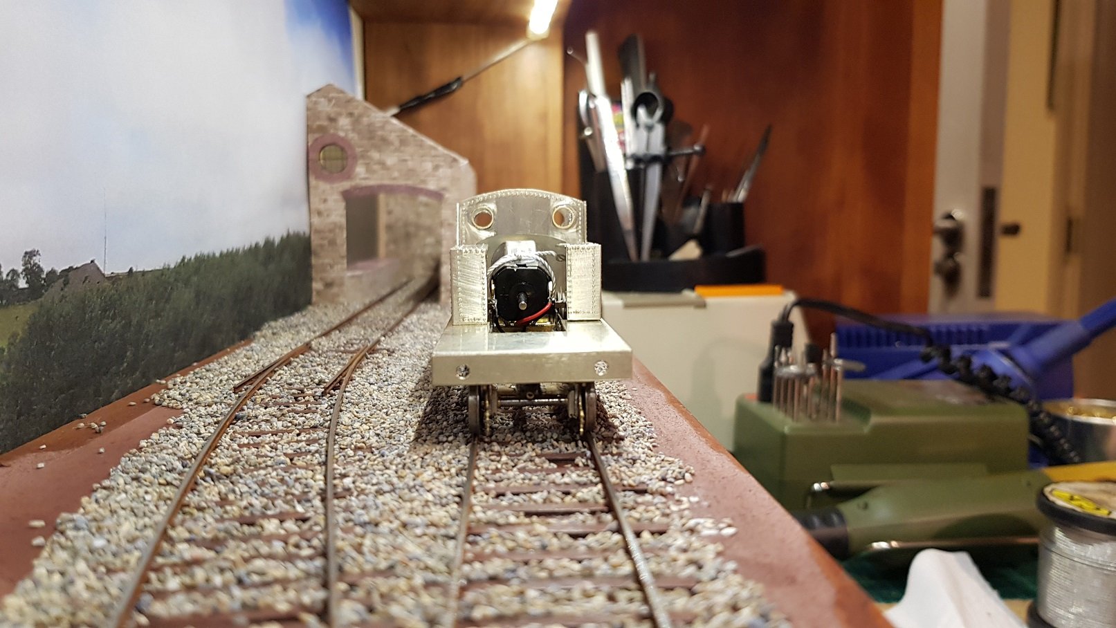
Build progressing nicely. Got out the rivet punch once all sides were properly shaped. Rivets added in a similar fashion to the prototype, but not exactly (just in case any rivet counters want to take me to task). I'm more in the 'effect' rather than 'exact' camp. I kept the front of the tank as part of the side and bent in once the rivets were added. It was over long, and then trimmed to the dimension once the boiler tube was offered up. There may be some final tweaking needed, but seems to fit quite well at the moment. Out with the soldering iron and bunker rear in first on one side followed by the cab back; other side was then fixed in place. I'm keeping the cab front loose for the moment so I can fix that little error once the boiler is in place. All assembled including tank tops we get to this: Bunker tank sides and tops need to be fabricated and installed next - line of rivets on the bunker back have been pressed and can be seen on the photo above. Spectacles on the windows were created from thin cuts of 6mm brass tube filed and sanded until smooth and thin. Bit tricky getting them all the same size - I think the are all pretty much equal - 'ish'. Body was then dry fitted to the footplate for fit. And then onto the chassis to get a look at how it's all coming together A head on view with the body on. Proportions are starting to look a little better - improved camera angle no doubt helping! That little error with the cab front is a little more evident in this photo, hence - keep it loose for the moment until I know what repair is needed. All for now - till the next time. Ken
-
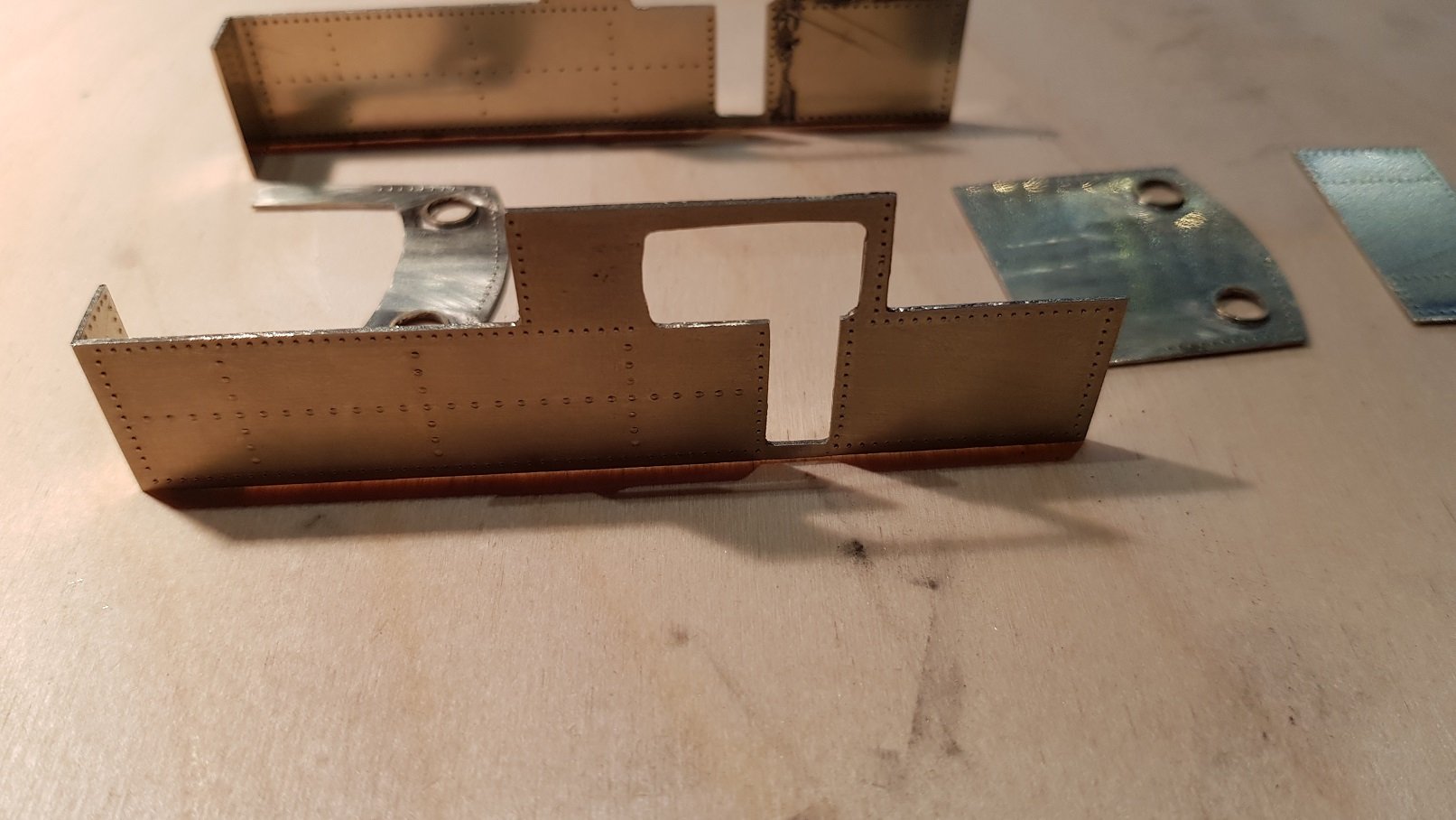
Getting a run at this. Cab sides were marked and cut out - the P-slot for cab door and window was quite challenging, and needs a little more tidying up. Cab Front and rear were also marked and cut out. Drilling out of the windows caused some burr issues which needed to be filed down, however this then scratched the surface, so some flat sanding with wet and dry will be needed. Can anyone spot the little / big mistake..............Hmm............Looks like the cutout to clear the motor is a little too wide at the shoulders and probably will not be covered by the boiler & tanks. It needed to be the width and height to clear pick ups and motor respectively, but perhaps a more triangular shape would have been better. I may need to get everything into place before soldering in the cab front just to see how much tidying up is needed. I can always add filler pieces with solder and sand to a smooth finish. Anyway.... When all are cut out and filed, we get the following parts almost ready for assembly. Some sanding carried out on the cab front and rear, but more needed.. The sides will need more fettling and cleaning up before i put them together but it's progressing well. While working on the footplate the other day, I also made up the forms for the smoke box. These will be spaced with bolts and some scrap brass initially until the wrapper is added. Bolts can then be removed leaving a nice smoke box (well hopefully anyway) That's all for now. Ken
-
Track work and point rodding is very nicely done also!
-
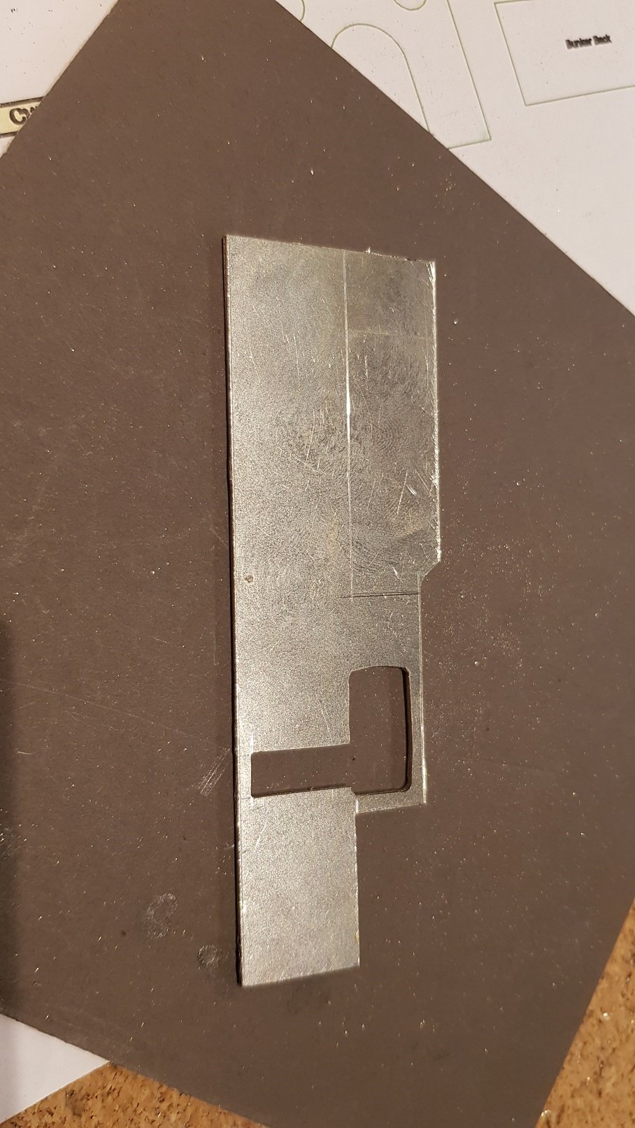
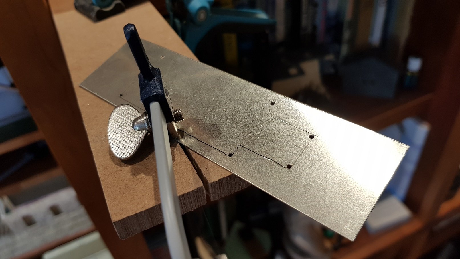
Got some more work done this weekend. Starting on the body. So, footplate first. Basic shape cut out and internal shape cut using piercing saw. This tool can definitely be said to operate on the Ouija Board principle - It transforms human energy into a crooked, unpredictable motion, and the more you attempt to influence its course, the more dismal your future becomes. As wavy as those lines look, this is not a bad effort in my books. Anyway, this all gets cleaned up with files and squares to make sure all is straight. Once this is done, buffer beams and valances are needed. Front buffer beam installed, followed by the valances, which in this case are 1mm x 1mm angle. This both provides the visual valance, but also provides considerable strength; a little bit of tweaking to get in all flat, and we arrive at: All good so far. Now to try on the chassis. Without the body, there appears to be a lot of overhang from the wheels to the sides of the foot plate, but a quick check back to the drawings to confirm that it is just over 9 feet (scale) wide. I never really noticed the difference between the inside line of the rail and the outside of the frame, but in this instance is the best part of 2 feet. Head on, it looks a little better, but once the body is filling out the shape, it should look better. (Straighter camera angle would also help!!) Sheets dimensions and tacked together to start work on the cab front & rear as well as sides. More, as time permits, Ken
-
Eoin, Consider changing to larger gears on the axles? Problem I had with the 495 was the kit came with a 23 tooth gear rather than the 20 tooth needed - difference in diameter was c. 1 mm but too large to fit the gearbox I had. Might be enough to pick up the slack - re-cutting the chassis and moving the bearings up will be pain!! Ken
- 136 replies
-
- 1
-

-
- class f
- west clare
- (and 1 more)
-
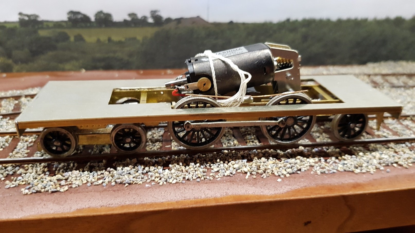
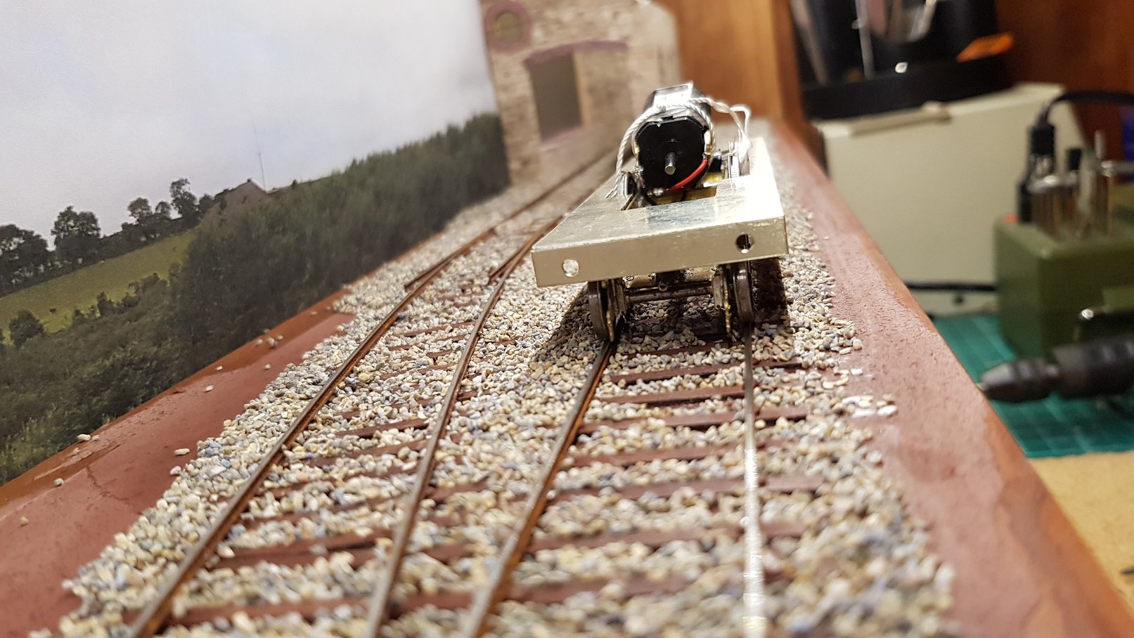
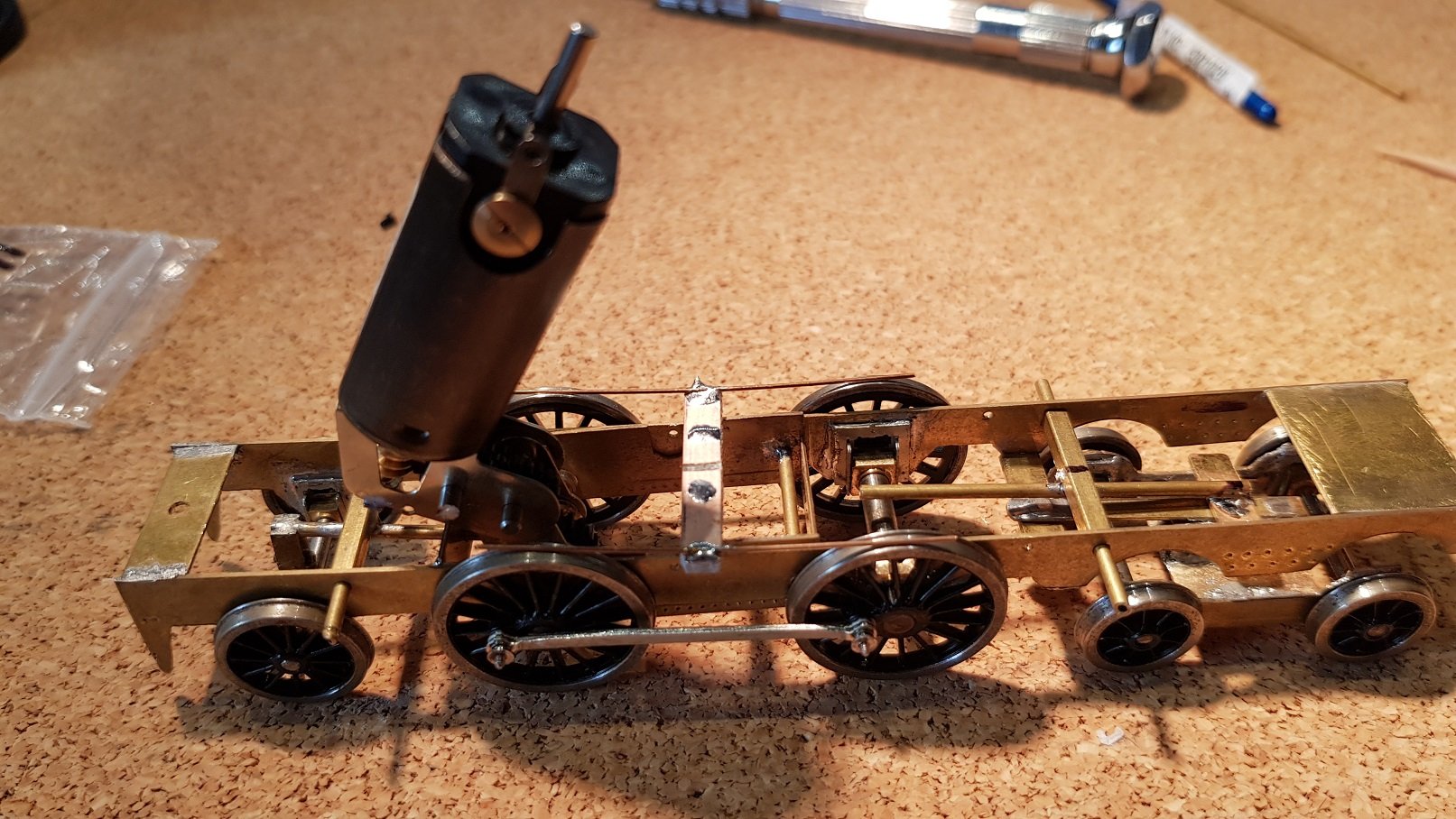
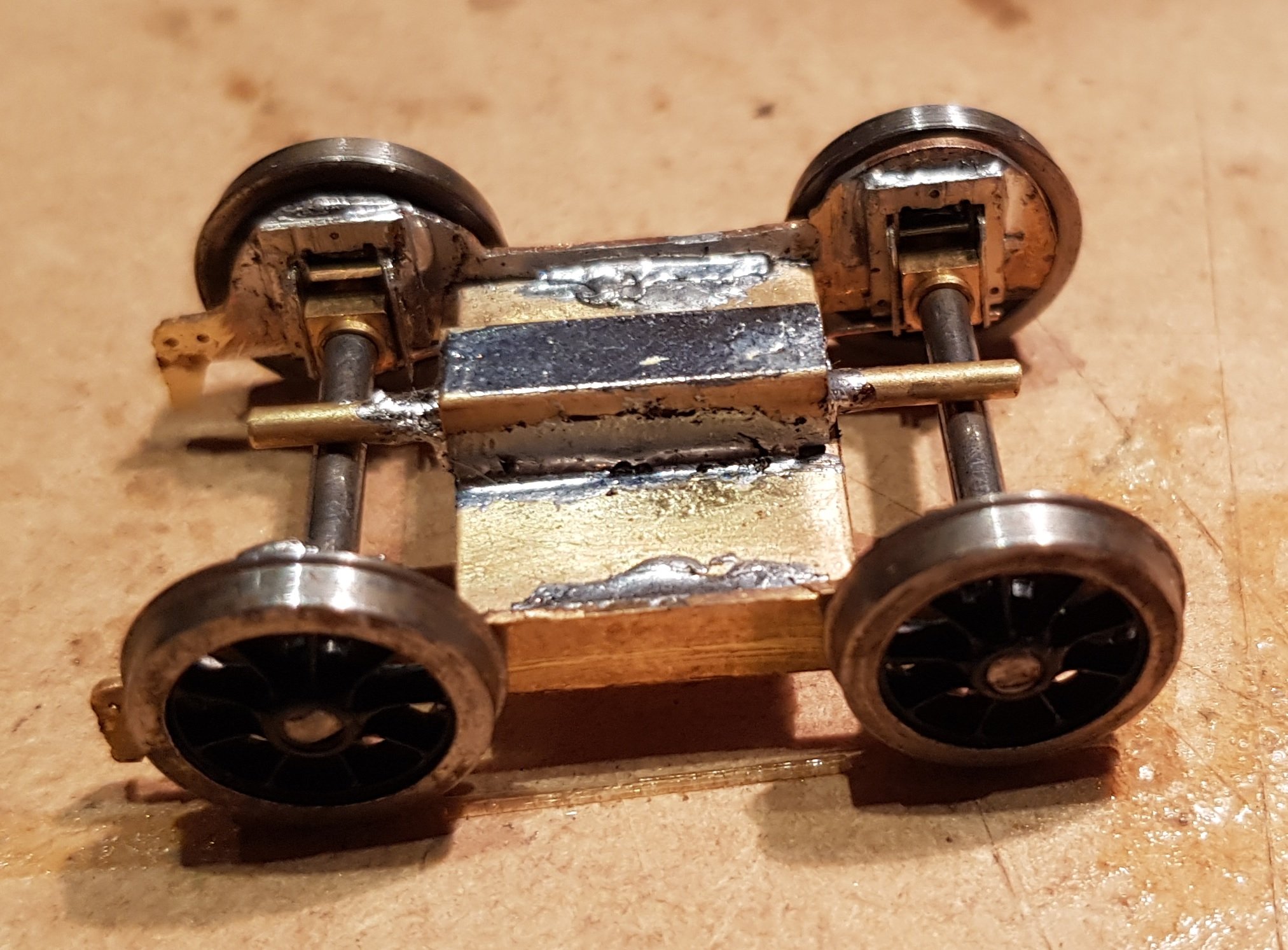
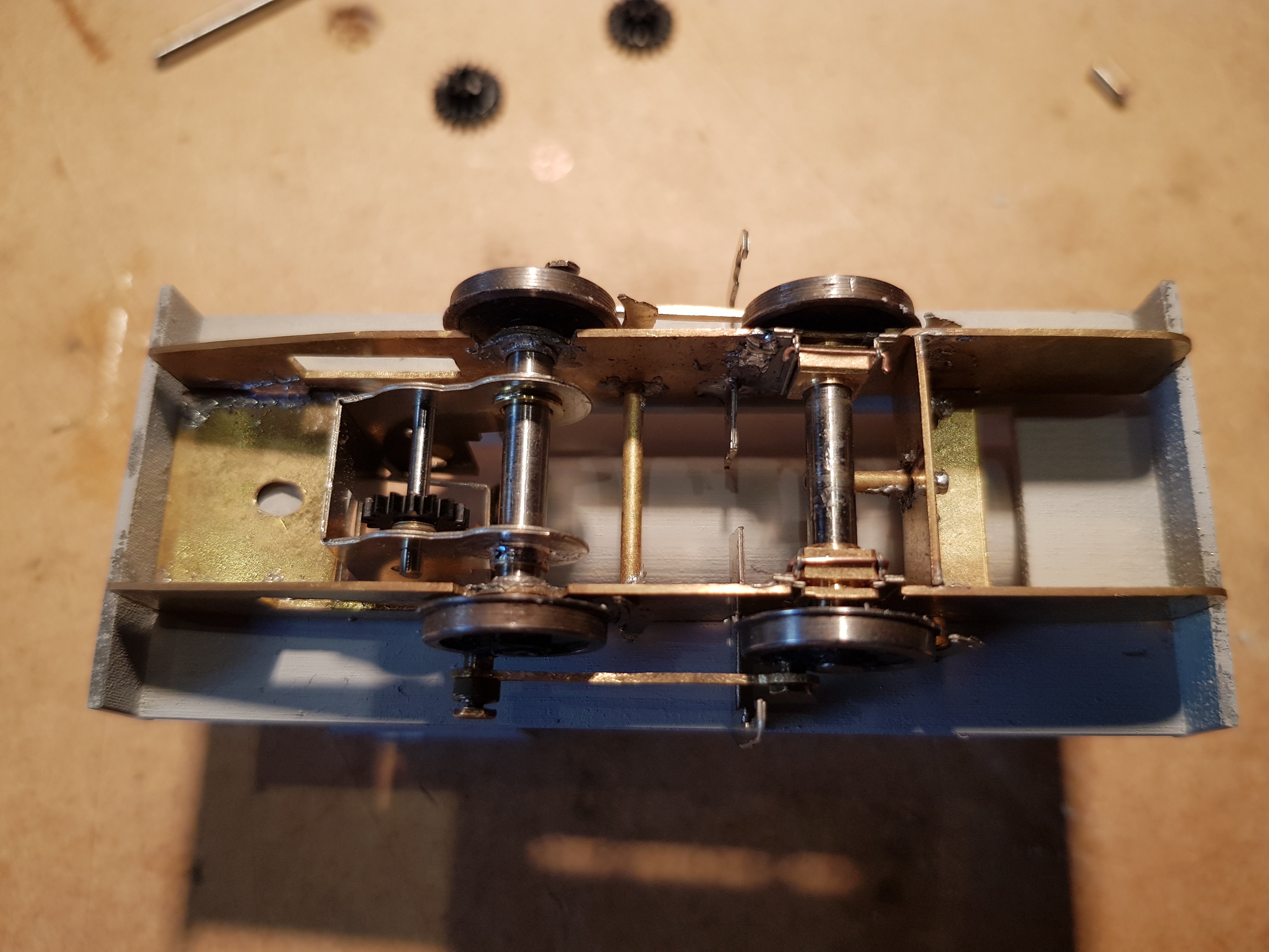
Progress to date. Bearing pad for bogie has been trimmed back to rest on the centre of the bogie which now applies equal pressure to the wheel sets. Simple "wiper" pickups were added by using copper clad and some phosphor bronze wire. The copper clad is fixed to the subframe, so the contact withe the rear drivers is assured, while contact on the front drivers will depend on track conditions. If the front drivers flex, they may loose contact with the pickup; there is a fine balance here between maintaining contact and excessive spring force from the phosphor bronze. Depending on how the chassis performs, I may put pickups on the trailing wheel, but so far, so good. Motor was wired up and put on the test track to see how it performs. The string is to hold the motor from moving under torque which can be fine tuned later with some cable ties. And behold a running chassis - Eh, No. Much, and I mean much, fettling later with axle bearings and coupling rod holes we have a running chassis. Slow speed could be a little better, so more fettling may be required to just iron out those very minor sticky points. Other than that, we have a fully motorised and compensated chassis. It does need weight to let it run smoothly as the weight is distributed over all axles and not just the drivers, but that can be sorted once the body is constructed and the whole unit run as one. Very happy with progress so far. Onwards and upwards!! Ken
-
I would be interested, but like other would like a little more information if possible. Ken
-
Then calmly reach for your extensive list of handy expletives and use the most appropriate one for the occasion. Gently unsolder the joint and re-solder the correct way! Ahhh....that's better..... Ken
-
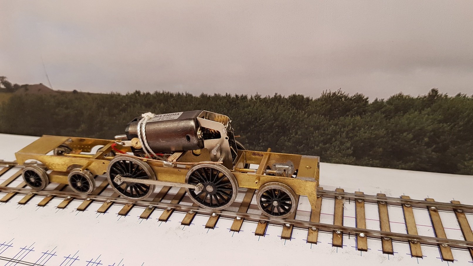
Made some good progress over the weekend Bogie frames were cut out, frame spacer and mini hornblocks installed. Soldering work really needs more practice A compensation bar was installed through some box to control axle movement and add some height for connection to the main chassis. A compensation unit was constructed for the forward chassis which would provide equalisation between the bogie and front driver. When all assembled, we get to a basic rolling chassis which is now running at the correct height. Some minor fettling may be required once the body is on, if there is any forward or rearward leaning. Gearbox was next. High Level Roadrunner+ to allow some movement and articulation if needed. May be over the top, but we'll see as we go along. Bearings soldered into the etch, parts folded and gearbox assembled to arrive at... Crankpins (Alan Gibson) were installed in the main drivers and a set of coupling rods were constructed, again from an Alan Gibson etch. Coupling rods appear to be my kryptonite though; opening out the holes for the crankpins with broaches inevitably leads to slight twisting of the coupling rod at its weakest point. It takes some amount of work to get them straight and level to allow soldering to the corresponding etch. Need to work on that!! But when all that is done, we finally get to a rolling chassis. Well, almost!! Few things to adjust. Quartering on the wheels is not 100% and there is a very slight bind that needs adjusting. The bearing pad on the front compensation unit is too far forward and is putting weight on the leading bogie wheels rather than the bogie itself which will need to be adjusted. Coupling rods need a good tidying up with the file to get them looking semi-normal. Once I'm happy with the compensation, the pins need to be cut back and soldered to fix them in position. So now, a fully compensated chassis with movement on all axles. Excellent, except its like an octopus trying to get it onto the tracks; everything moves, so its necessary to set each axle on the track, one by one, however, when it is on the track, the movement is something to behold - it just ripples over any imperfection in the track. Next up - electrical pickups, temporary fixing for the gearbox, motor install and a test run. More later Ken
-
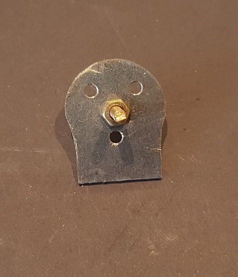
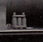
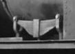
Can anyone point me to a source of locomotive springs as per the photos. These are samples of driver and pony springs from Irish locos. Thanks in advance Ken
-
Hmmm.... By my calculations the scale should be smaller than the 7mm, as you are trying to use the 32mm track to model 5' 3". Thus if 32mm track equates to the 1,600mm prototype, the scale must be 1,600 / 32 => 1:50? I would agree with David - it's probably easier to construct track than to scratch build every element of the model in an unusual scale. Ken
-
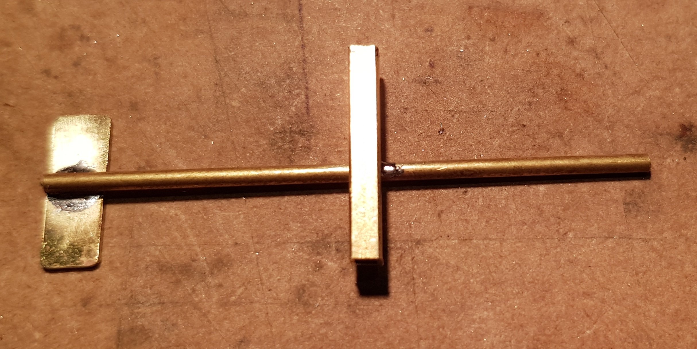
Little bit of work last night. Built the compensation bar between the sub frame and the rear axle. Tricky little bugger to put together - all parts are very close & soldering led to things moving around enough to cause me to revert to my collection of expletives! Simple in theory, but tricky to execute. How it operates Once the bogey and front driver are installed, this compensation unit will set the height for the rear axles and let them move around depending on track conditions. the range of articulation can be seen from the two photos. Just to put this in scale - the distance between the frames is about 17mm. Working on the bogey at the moment and will post some photos on progress shortly. Regards, Ken
-
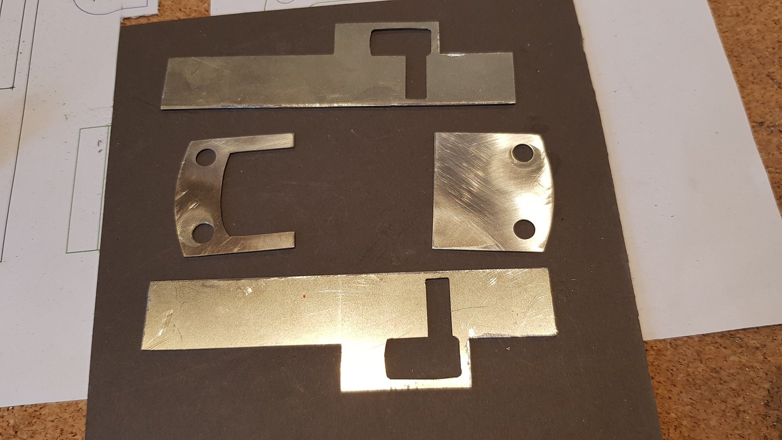
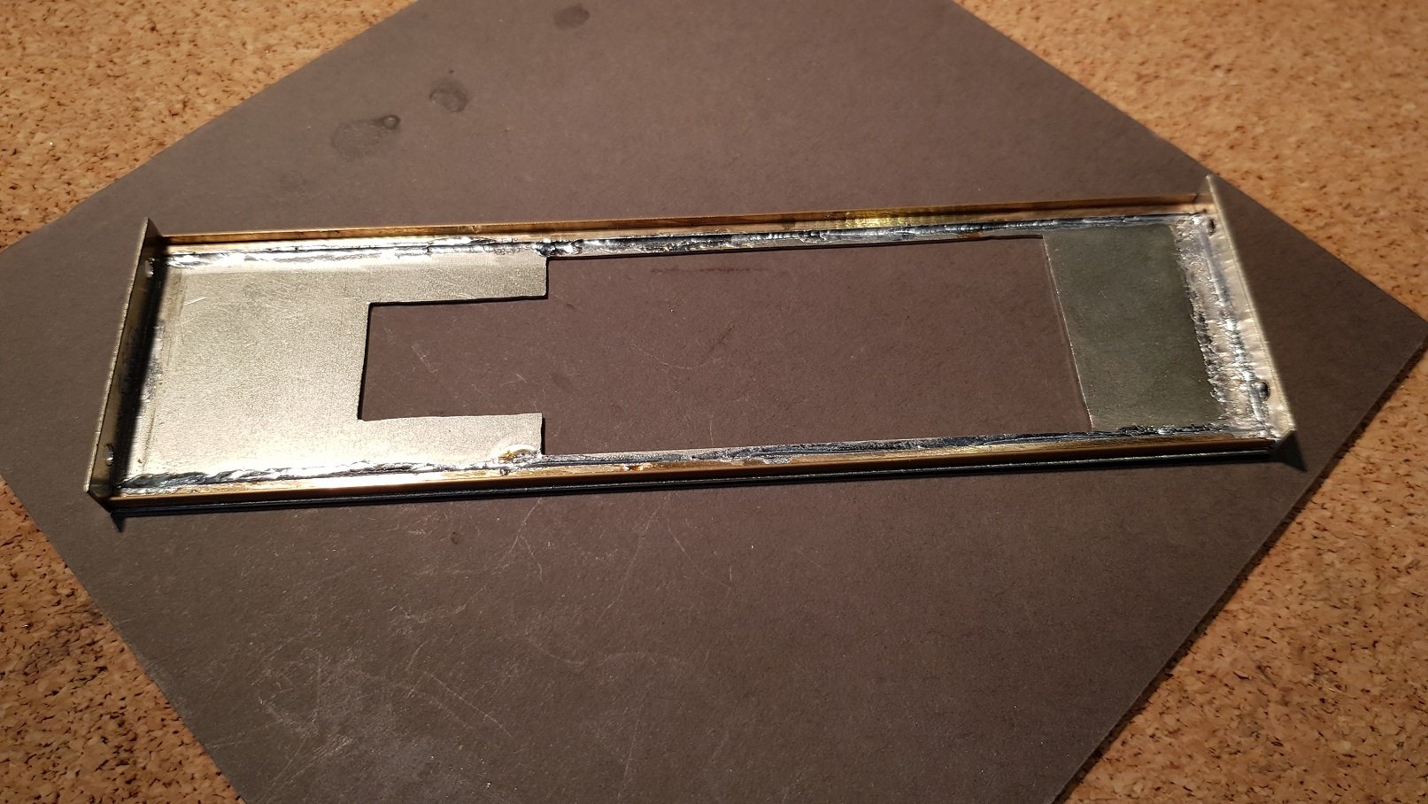
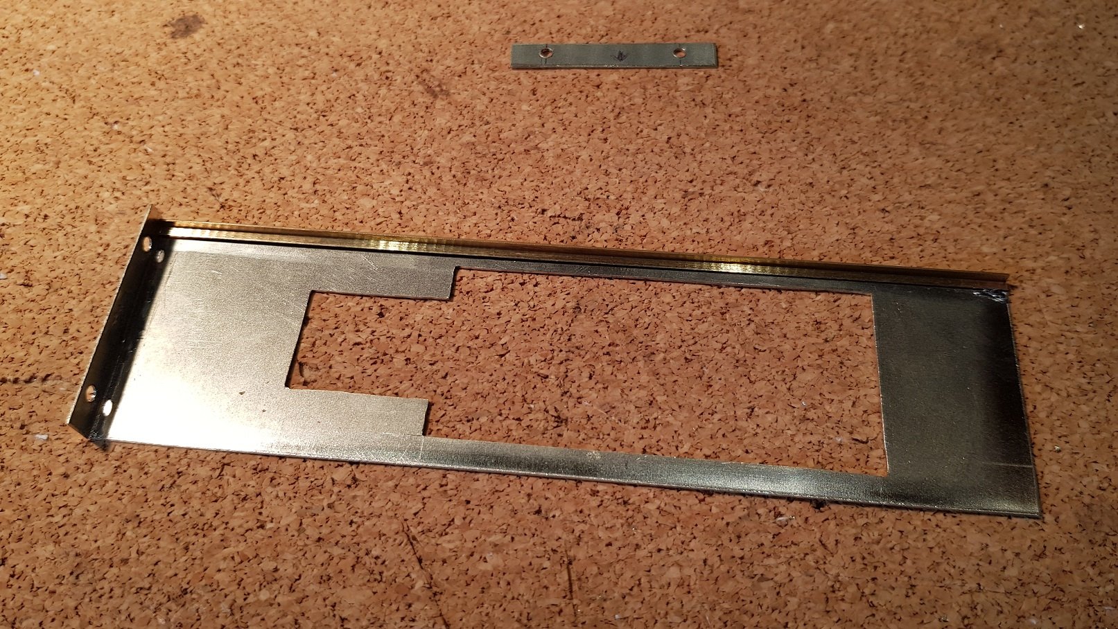
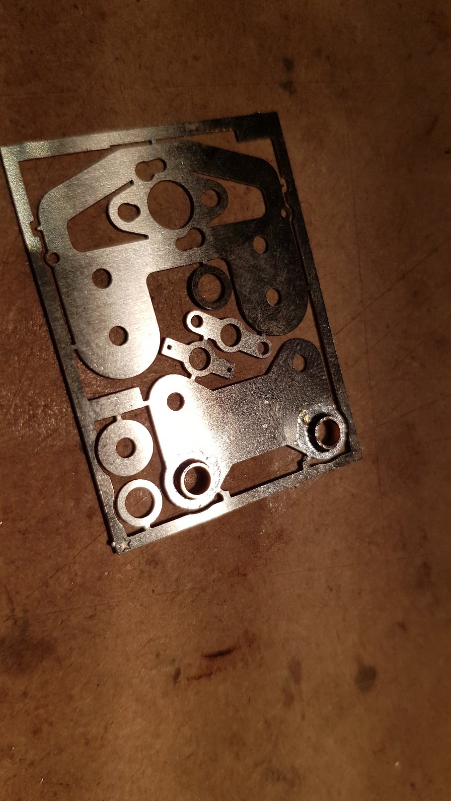
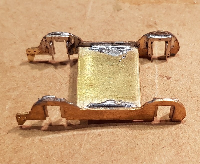
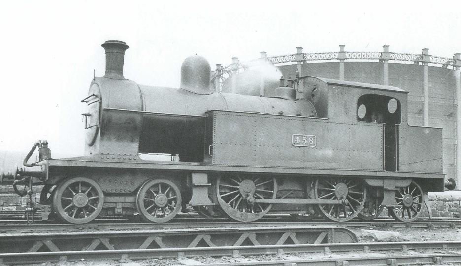
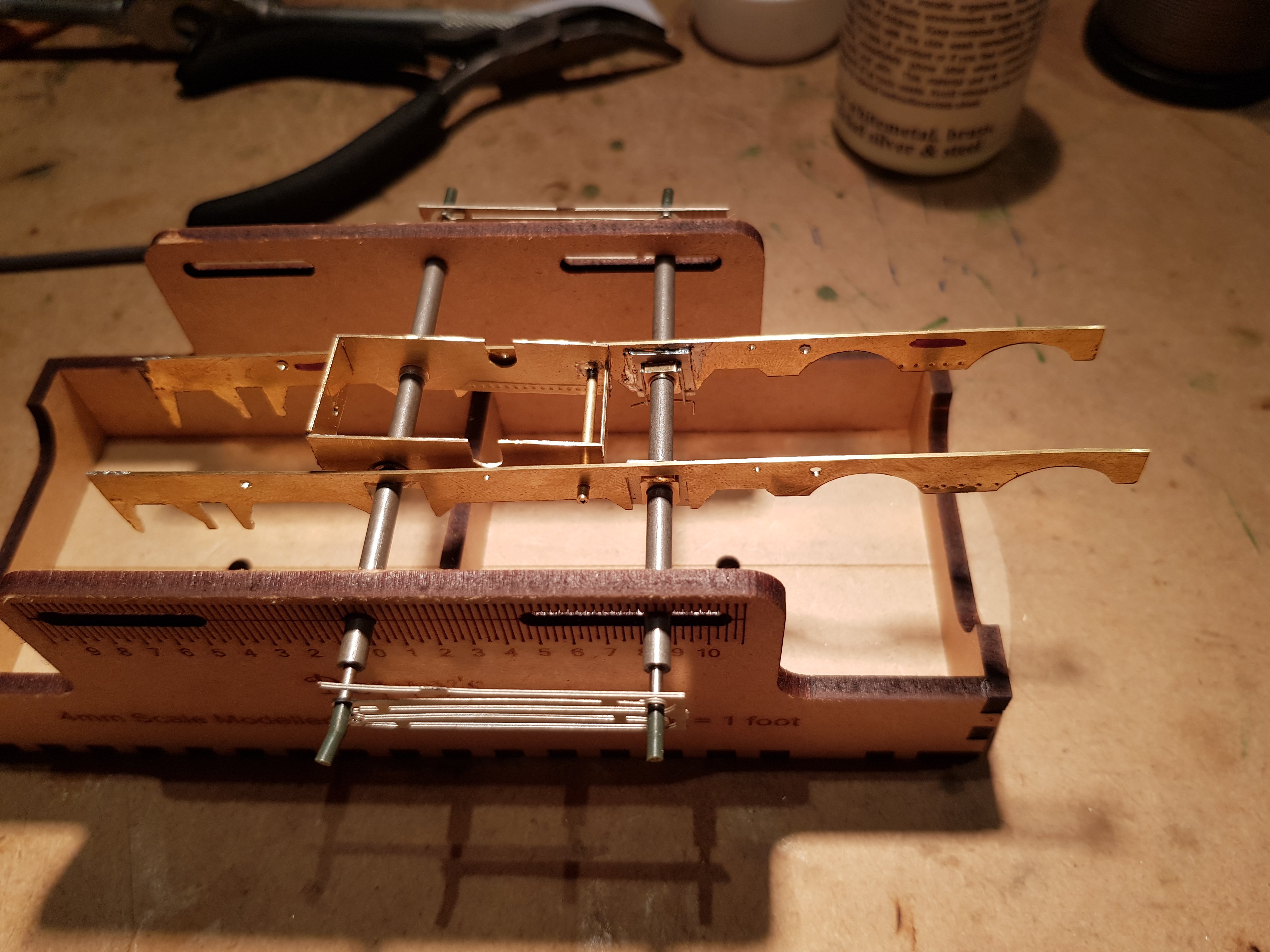
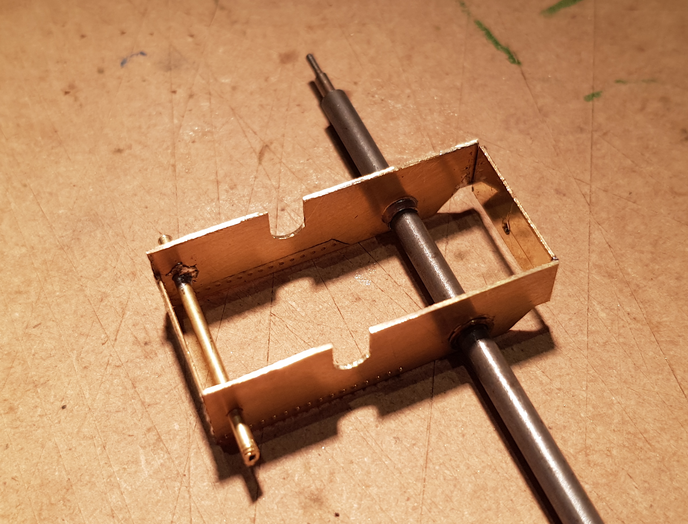
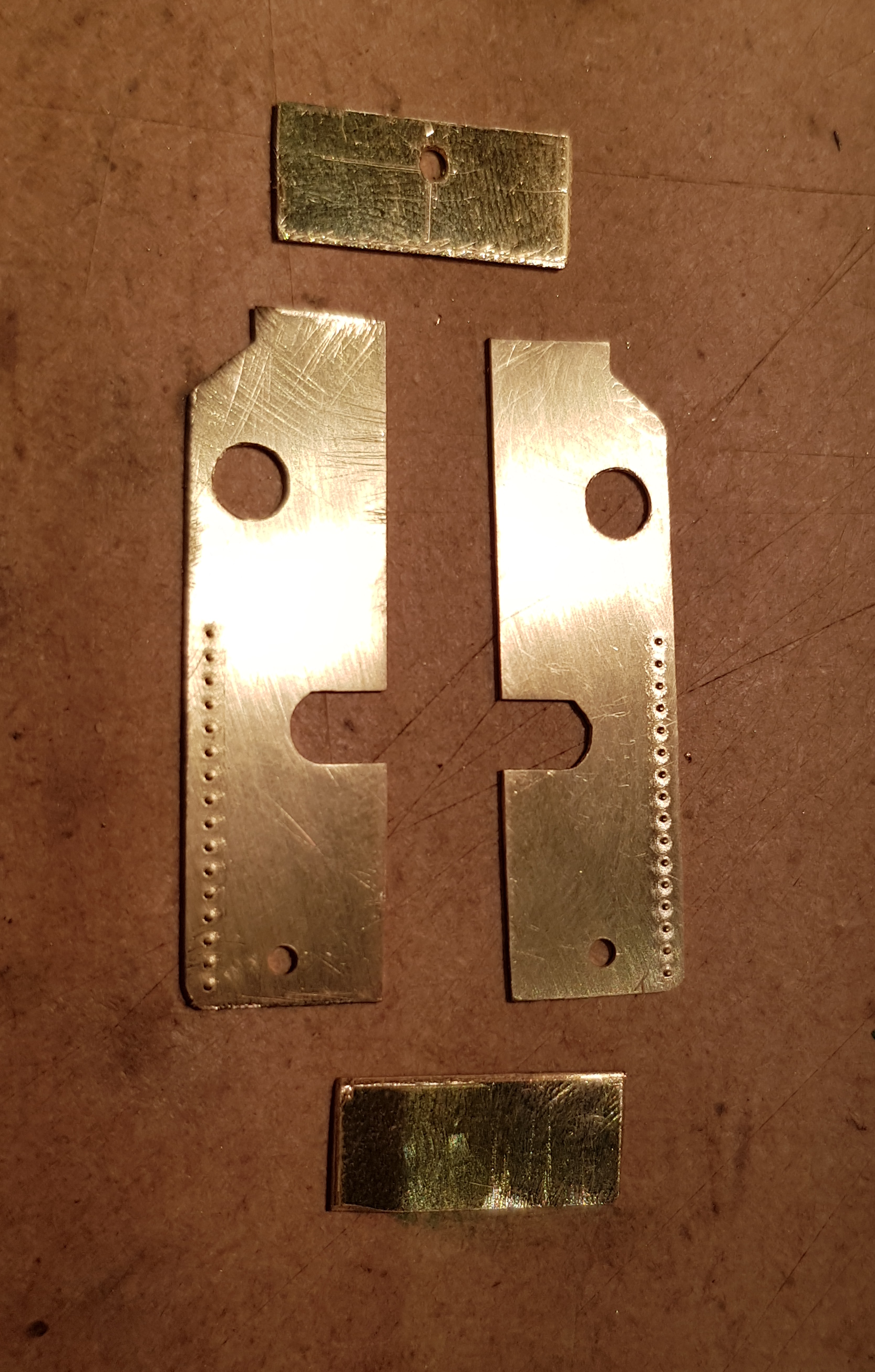
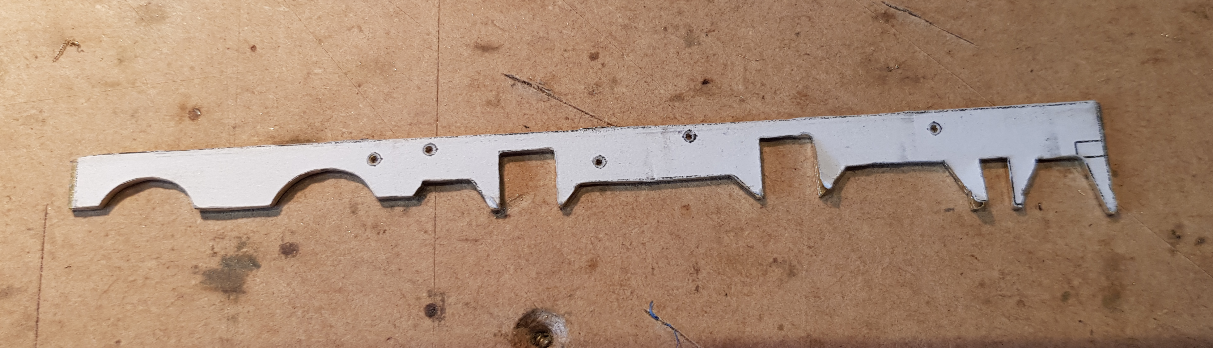
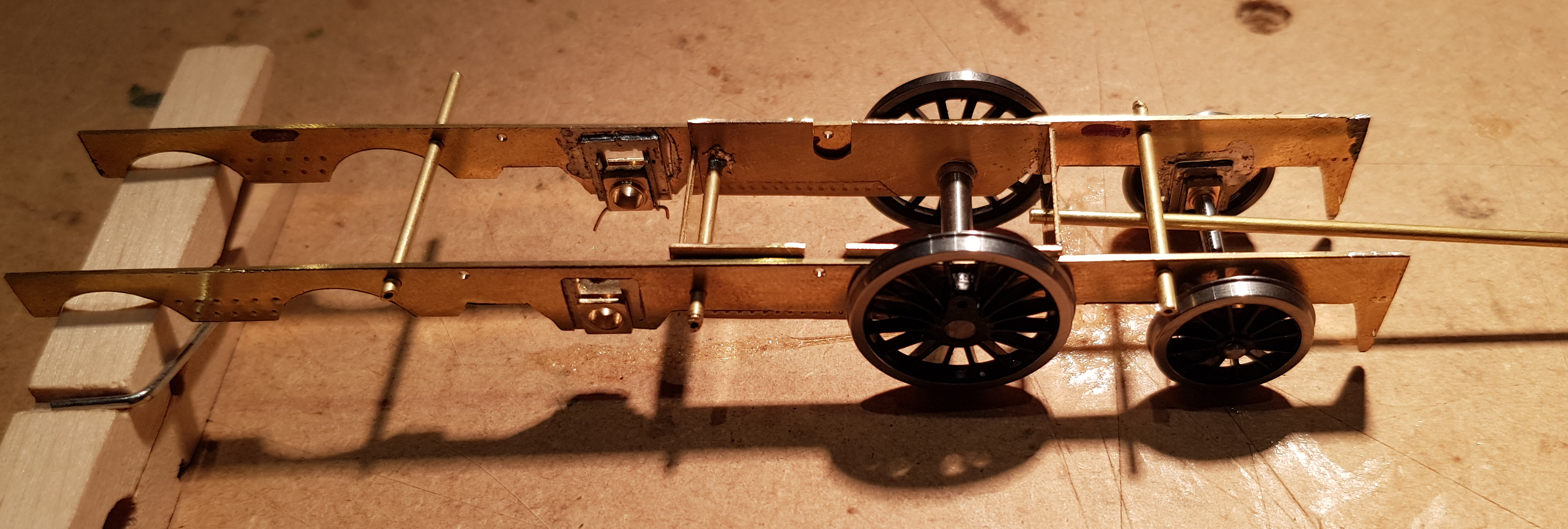
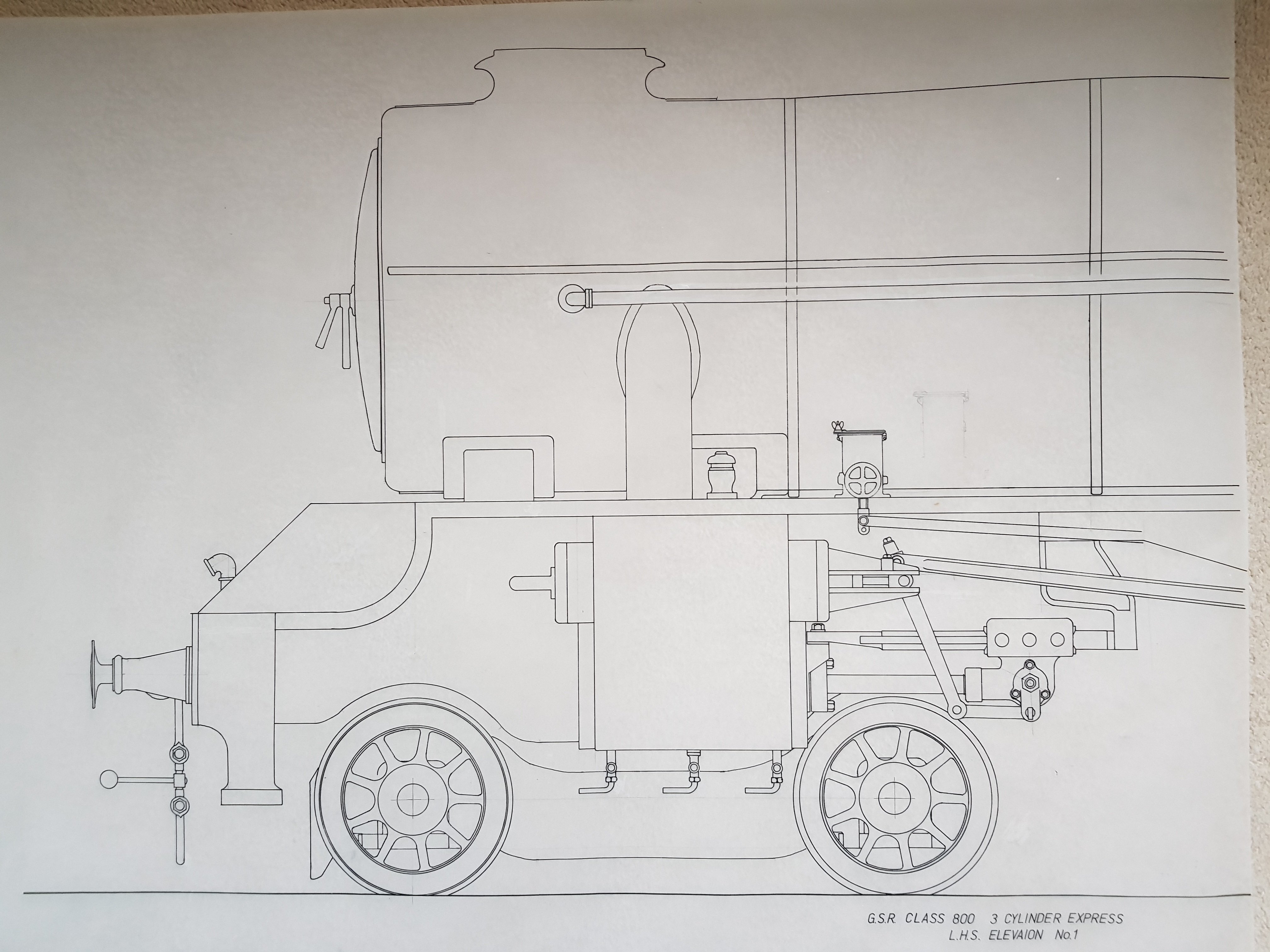
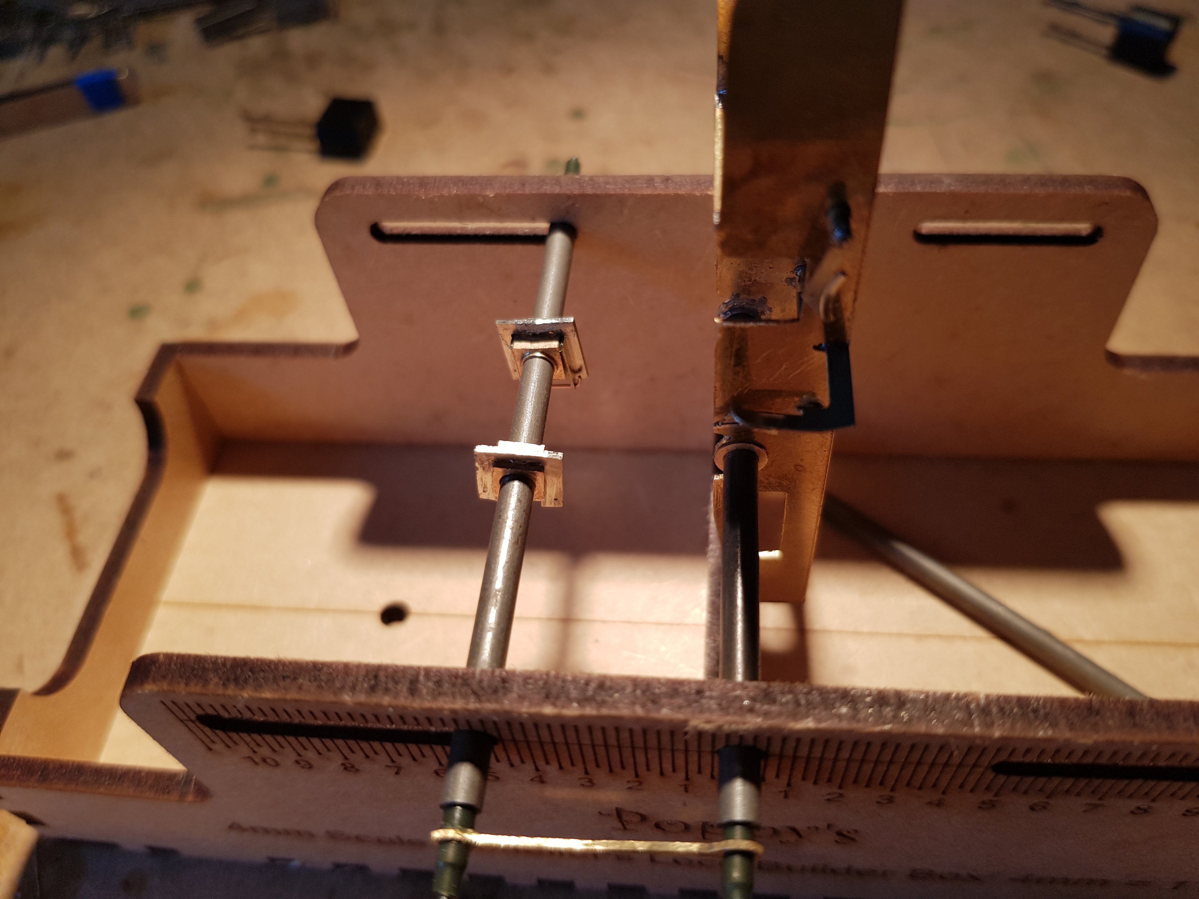
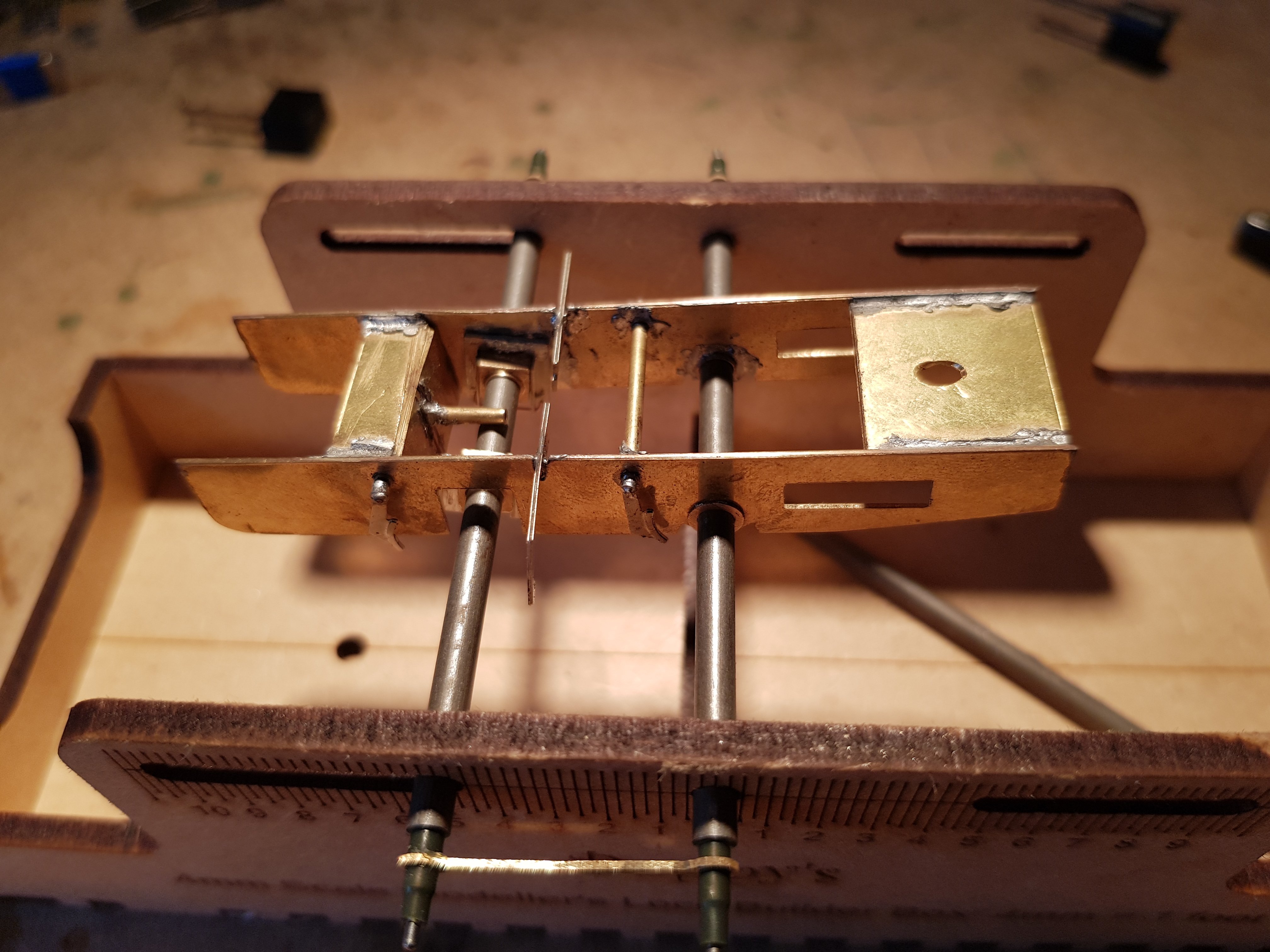
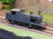
As a break from the 495 build, I decided to start on another locomotive. This will be my first foray into complete scratch building and have chosen the ex DSER No. 52; 4-4-2T, GSR Class 458, as a starting point. This loco class was long lived (1893 - 1955) and provided good service on the DSER section but given its life, it could reasonably appear in a wide variety locations and with different demands. Photo courtesy of the "Good Book" (Clements & Mc Mahon) I met with the good folk from the IRRS who were kind enough to give me access to the outline drawings which helped me develop up my own CAD drawings as an aid to building the loco. What is interesting is that while the IRRS drawings are dimensioned, they are not to scale, so some tweaking was required to get a more accurate drawing to work from. First thing need were the frames. While it would be nice to create the frames in total (including the projection either side of the smokebox) it was easier to separate these into two sections. Once they are put on the footplate & mounted on the frames, it will make little difference. This template was printed out and checked for scale before cutting (yes there was an earlier attempt!) Two lengths of brass are tacked together, the template stuck down and cut with the piercing saw. The result of much cutting and tidying up with files to get to this point. I decided to compensate this chassis and am following the very good directions provided in Flexichas (Mike Sharman) who outlines the various methods of providing a fully compensated chassis. In this instance, a primary compensation unit is constructed with fixed bearings able to pivot around a forward fulcrum, and balanced by the rear trailing wheels. What's nice about this is it's in the location of the firebox so seves two functions. This unit was developed around the chassis drawing and was cut in a similar fashion to the main frames. A few rivets along the bottom will provide the illusion of the firebox. This was then assembled to give: This was inserted into the frames, the unit loaded into the locobox to set the hornblocks for the front driving axle. Lots of pegs etc were needed to get the frame and compensated unit to sit correctly before fixing in the hornblocks. 8'-6" coupling rods were used to set the distance and hornblocks soldered in. From this starting point it was possible to set the trailing wheels and their respective hornblocks. Some wheels were installed to get some idea of how the rear compensating unit will operate. At present a 1.5mm rod is located in the rear of the main compensating unit, which will pivot around the cross bar(?) which will then bear down on the trailing wheel axle. A vertical structure will be needed to make up the difference in height between these two units. Ride height can then be adjusted by tweaking the bar until the unit sits at the right height. The main compensation unit will also provide a good location for the gearbox and motor which can be fixed to this unit. Humble beginings, but a thoroughly enjoyable learning curve and looking forward to see how this turns out. A good source of information, and inspiration, is "Scratch-Building Model Railway Tank Locomotives" by Simon Bolton. Excellent read, even if you are not going to build your own locomotive - he takes away the mystery (and fear) of scratch building and is certainly influencing me here. More soon. Regards, Ken
-
Well.... Touched base with Chris in High Level and it turns out I have the wrong final drive gear - it should have 20 teeth, mine has 23, so new one on its way in the post. Good time to put this one to one side for a short while and start something new. Eoin, Many thanks for that link - I got the book. That chap takes painting seriously!!! It'll take some time before I get to that level, if ever, but fascinating information none the less. Regards, Ken
-
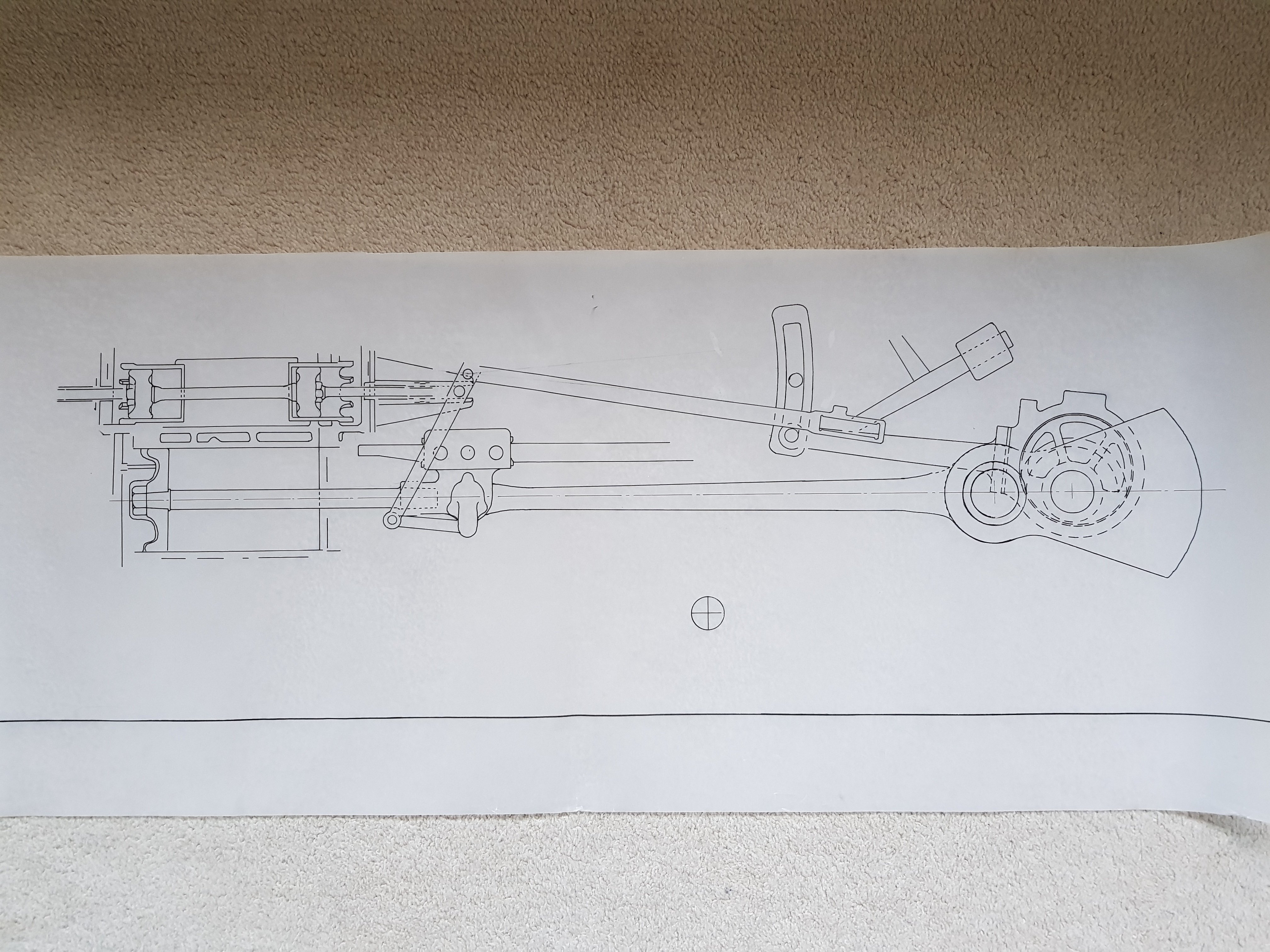
That makes sense! The cylinder positions are as below if that helps with the centre cylinder well forward to allow connection to the front axle. Another question is - are the wheels quartered, or is the system set up on 120deg given the three cylinders? Eoin - How are you setting it up on the model?
-
True, but what is more interesting is that the centre cylinder operates on the front axle which has the crank and valve eccentrics built in. The axle also has associated counterweights take up this imbalance . Thus, why weights on the crank and wheel - unless the front one is cosmetic?
-
Eoin, Many thanks for the links. There are a few images in there which will provide some indication of how she would have looked both new and old. Not having tried any lining, this should be quite a challenge..... JHB, Really appreciate the input, and I would agree that what ever the finish, a heavy level of weathering and toning down of the paintwork will be required. She will make a poor looking relative to the better looking locos to come. However, it should provide some very atmospheric photos with some heavily weathered and run down wagons. Will keep you posted on progress. Regards, Ken
-
Yes. The note on the drawing I have from IRRS states: "Purchased from Messrs Allman & Co. Ltd, Bandon for use on Anderson's and Victoria Quays" And while I have you, you being the Oracle on all things Livery, I have a note from the "Good Book" (Clements & Mc Mahon) that it maintained it's manufacturers paint scheme of Olive Green, lined in black & yellow with red frames. Whilst the photo is in B&W, there is no indication of colour variations or lining? Your thoughts? Ken
-
I'm sure we can forgive leaving out the underground car park!!! Looking fantastic as always - incredible level of modelling. Thanks for sharing.
-
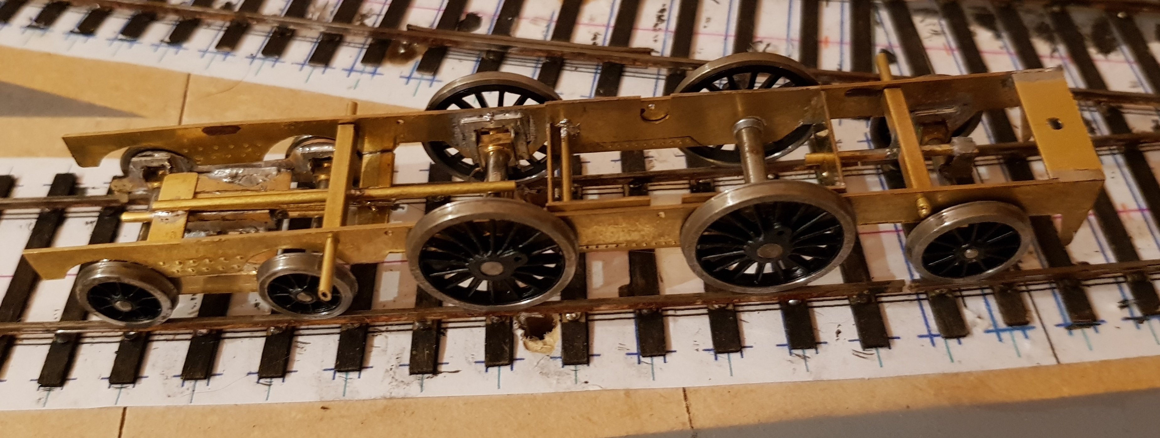
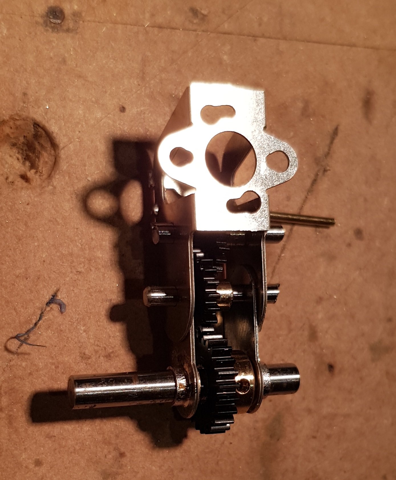
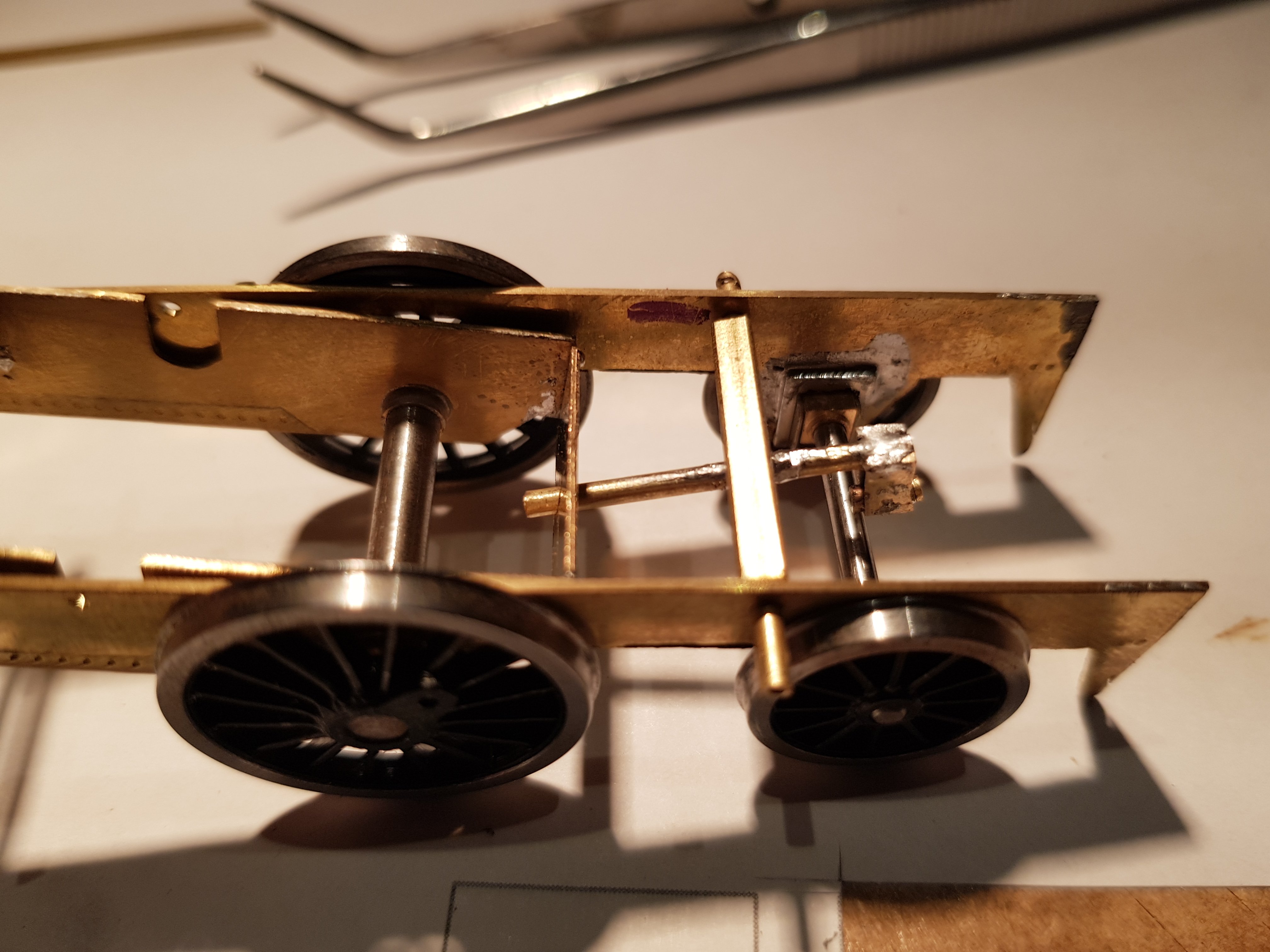
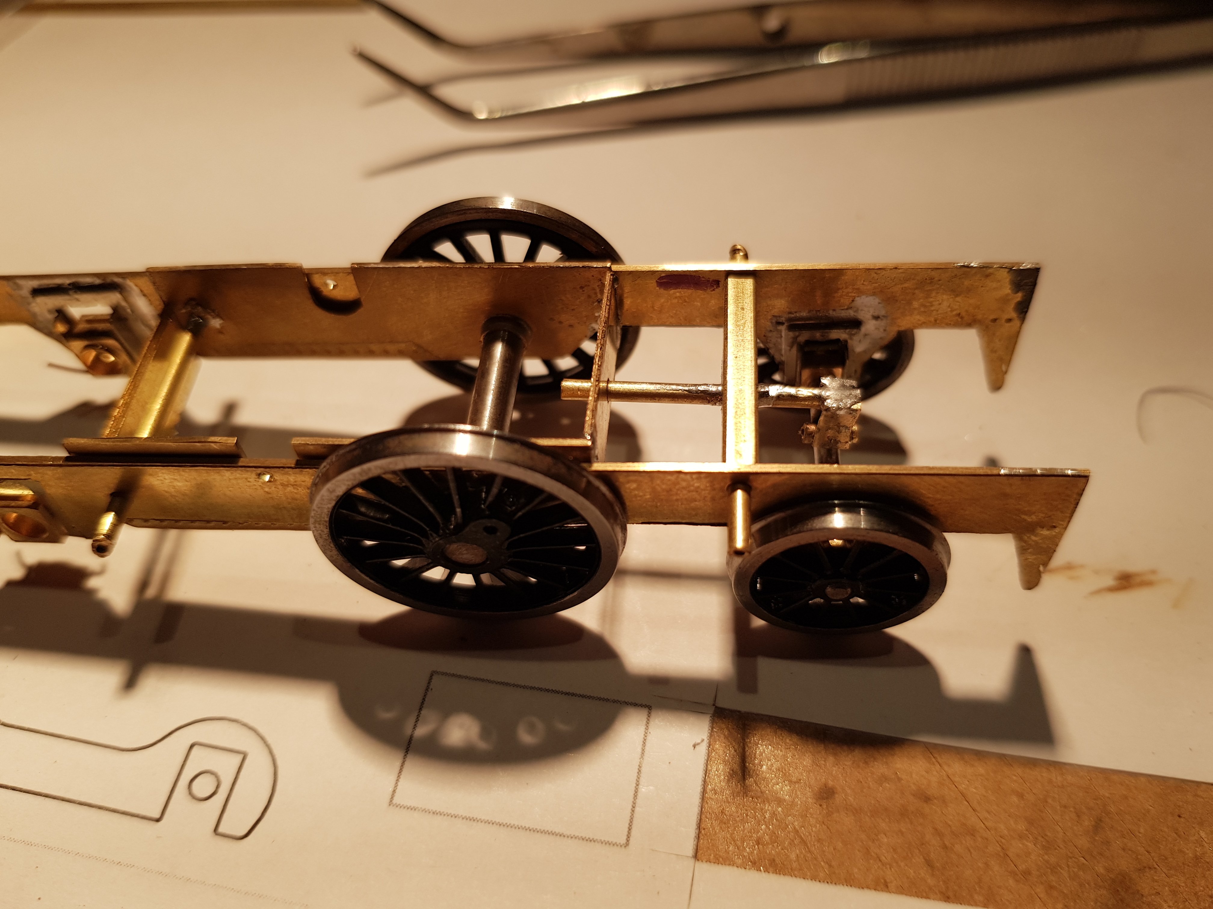
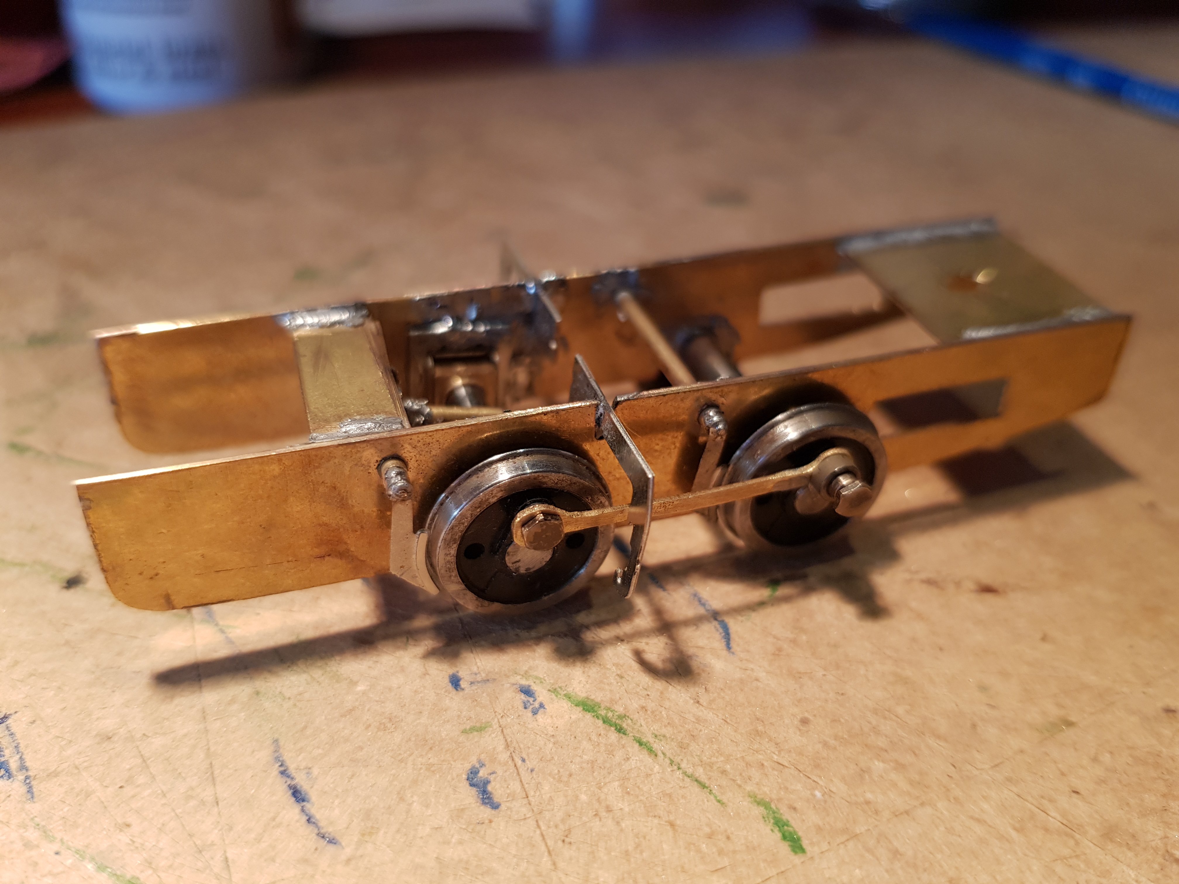
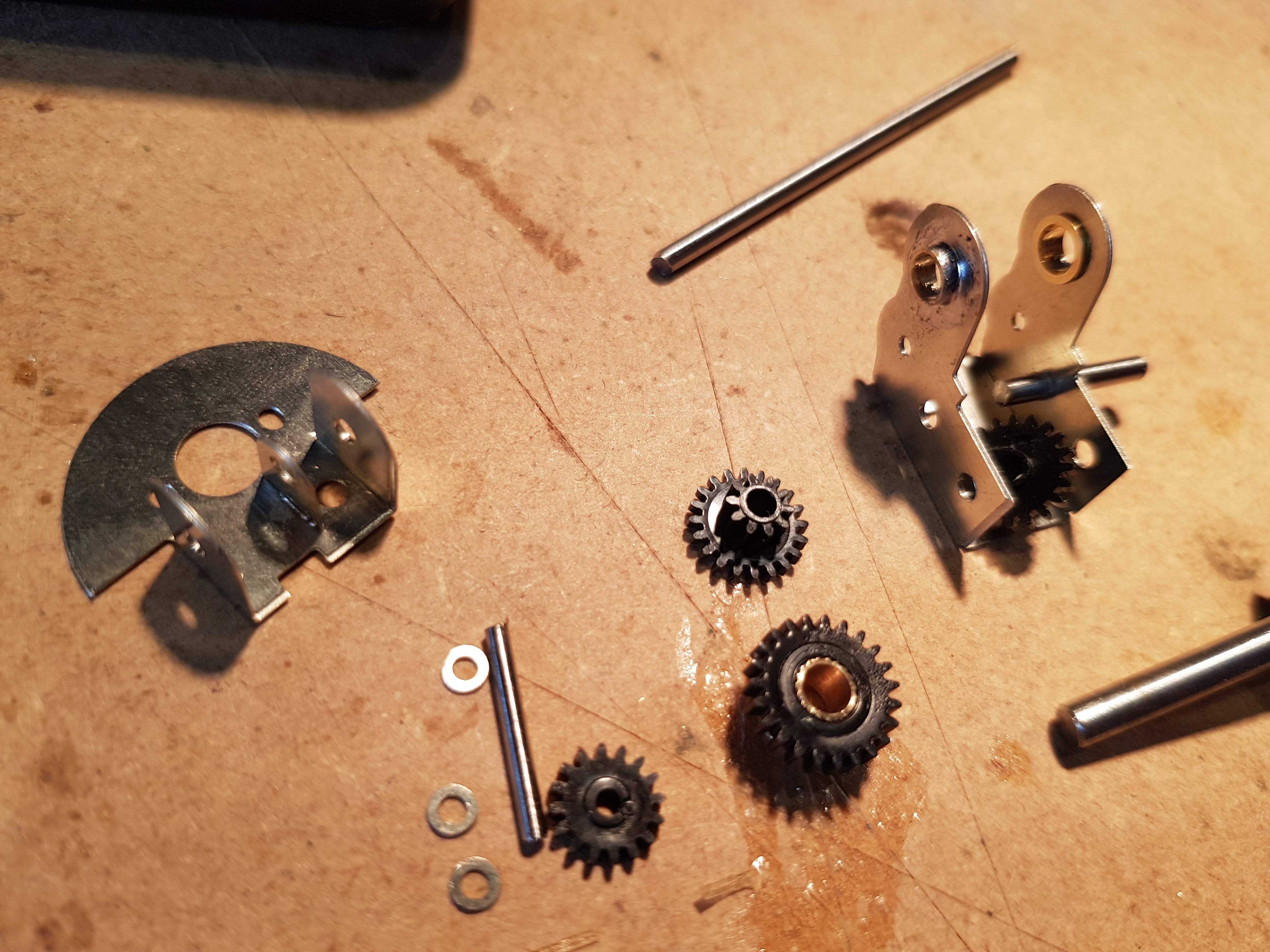
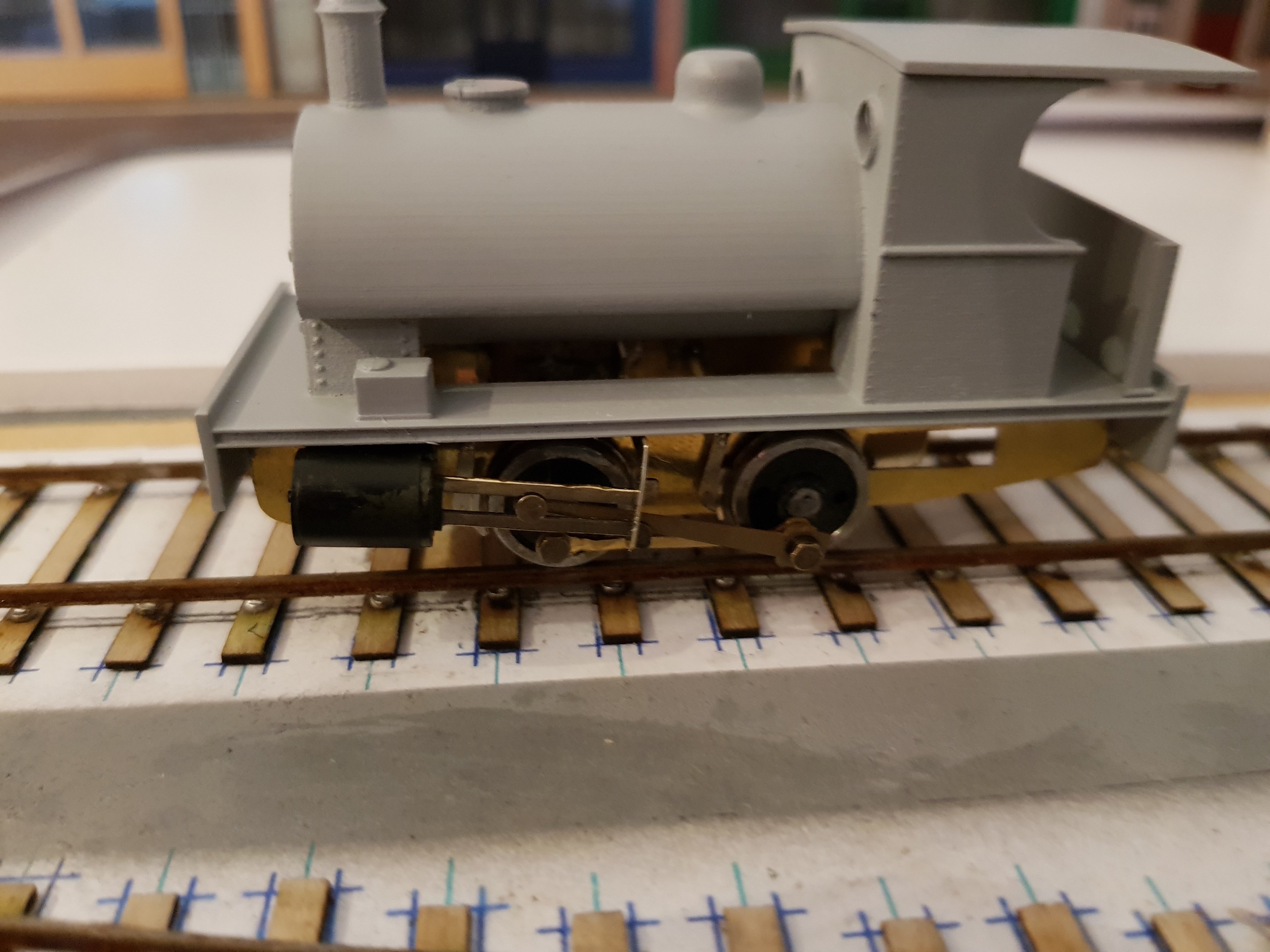
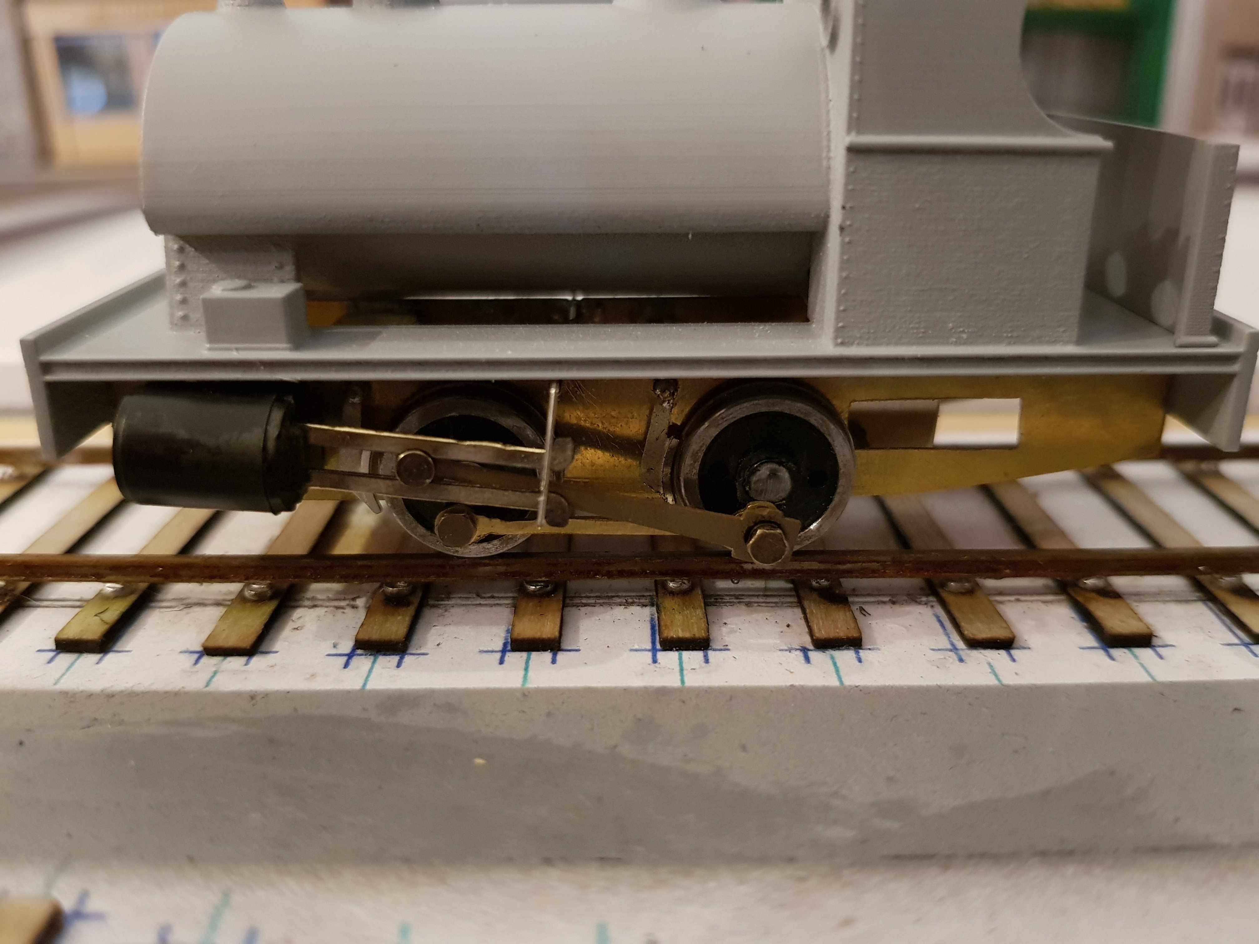
Progress for today. The new rods were binding slightly, so it was back onto the loco box to move the hornblocks properly in line. The axle posts allow the connecting rods set the correct distance and then its a matter of soldering in the horn blocks again. Relatively easily sorted, and now the chassis rolls properly without binding. Brakes were added from the kit and modified to suit the actual loco. Brakes are fixed to the 1.5mm crossing rod, which means they can swing out of the way to allow access to the wheels, while normally they can sit close to the wheel as per the prototype. Sliding rod supports from the kit were split and soldered into position using the cylinders as a guide. Next up was the gearbox which is formed from the kit etches folded up. All holes need to be gently opened with broaches to the correct sizes for shafts and bushes. Bushes were soldered in for the drive axle and assembly can commence. And this is where we hit a snag. When assembling the gearbox onto the drive shaft, it appears the gear on the drive axle (large one above with brass core) is a fraction to large to allow it mesh with the idler. No sequence of assembly allowed any space, so I think it will need a call to Chris in High Level Kits for advice. Gearbox connection to the drive axle - less the drive gear. This may need some lateral support as the space between the frames is much more than the kit envisaged, so without some fixing, the gearbox could slip. Perhaps the motor fixed in the boiler may prevent movement - I'll see how it goes. Continued on with other work such as motor into the boiler area, opening of the footplate to allow the gearbox through, and adding the cylinders. We are getting to a rather nice looking loco.... The wider frames move the cylinders out which gives a rather strong looking stance - shot from above showing how the cylinders sit in relation to the footplate. Very pleased with progress & its now starting to look more like the prototype. Ken