Mayner
-
Posts
4,969 -
Joined
-
Last visited
-
Days Won
121
Content Type
Profiles
Forums
Events
Gallery
Blogs
Community Map
Everything posted by Mayner
-
I have not used it myself, but some builders and chassis kits use what's described as "rigid beam suspension for all axles" using the swing axle arrangement. Highly recommended by CLAG for 0-6-0, 04-2, 2-4-0 and the most suitable for a 2-2-2 The High Level Dean Goods chassis and Arthur Kimber NER Tennant 2-4-0 use this arrangement, the leading (non driven) "swing axle" with the gearbox driving on the trailing or middle axle. I use the 'swing axle" with a fixed driving axle for compensating 0-4-0s and 4-4-0 tender locos.

-
Both the 60:1 and 80:1 gearbox and High Level 10x20 FE or 12X19 C (both 17,000rpm) motors should be suitable for a loco like an E on a fiddle yard to terminus layout. 80:1 should result in a slightly lower top speed than a 60:1. 108:1 is only really suitable for a shunting loco like a Pug, 03 or 08 diesel
- 309 replies
-
- 1
-

-
- mgwr
- 21mm gauge
- (and 1 more)
-
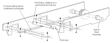
No springs are required with a compensated chassis. In its simplest form the driven axle is fixed, the floating axle/s are free to move up and down/rock from side to side supported by a compensation beam. There are more complex alternatives including springing http://www.clag.org.uk/41-0rev.html#section15 but beam suspension works fine for me.
-
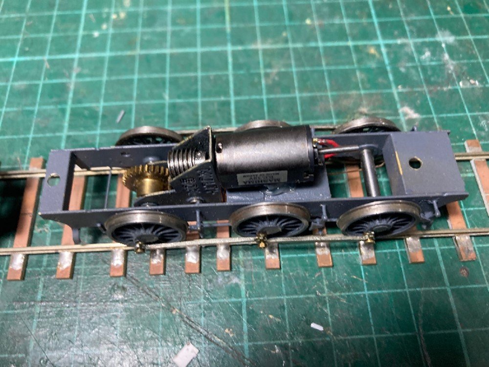
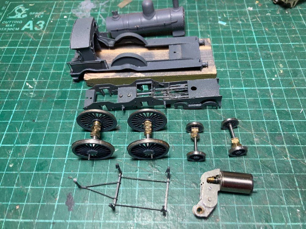
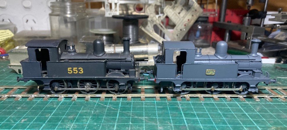
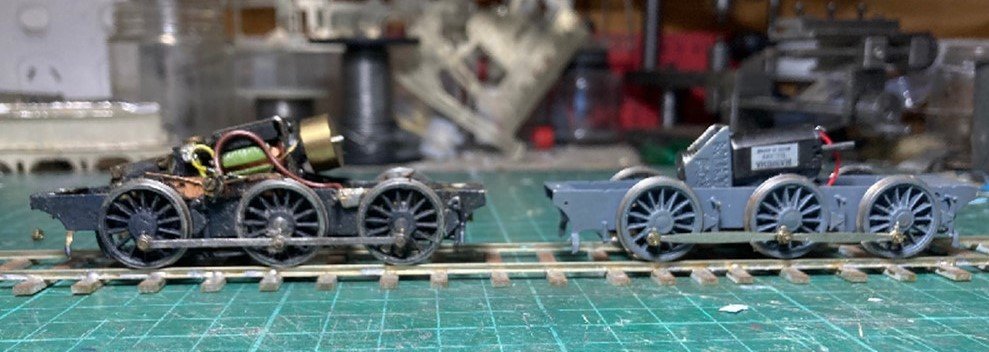
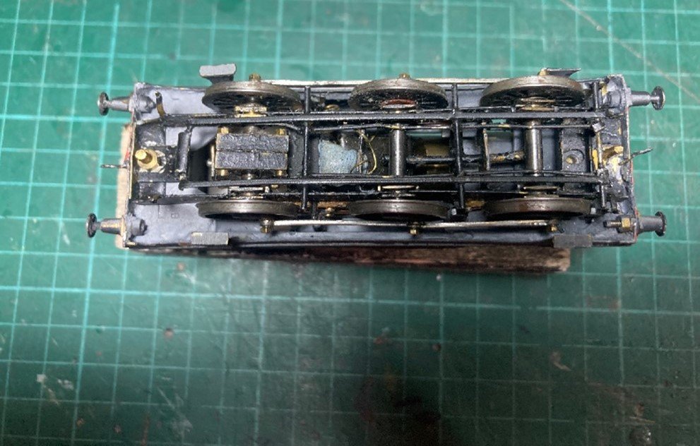
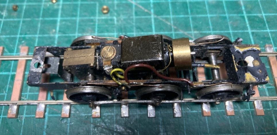
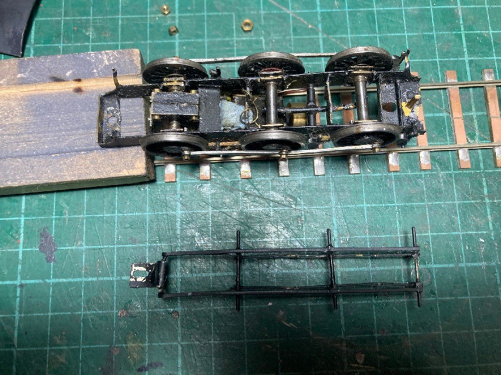
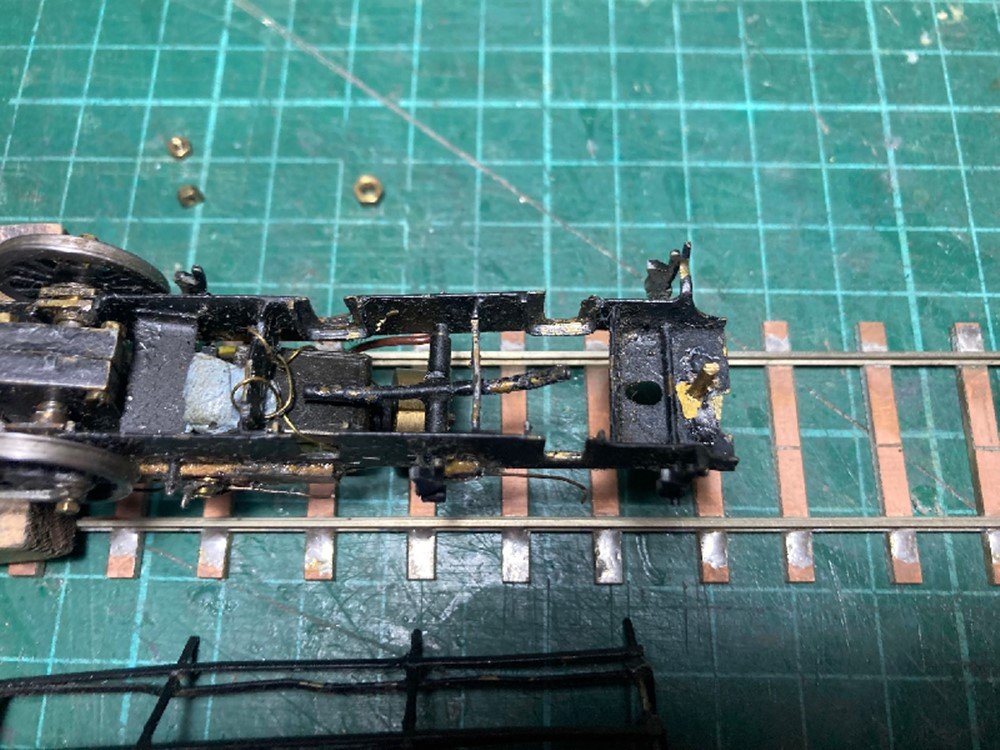
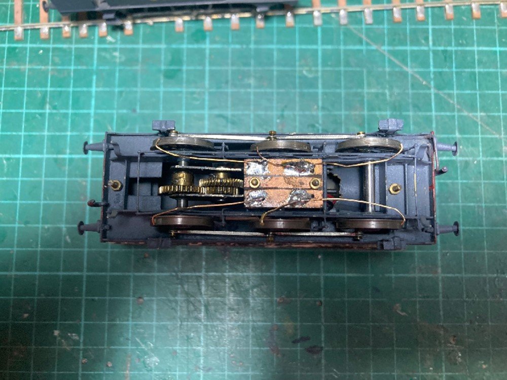
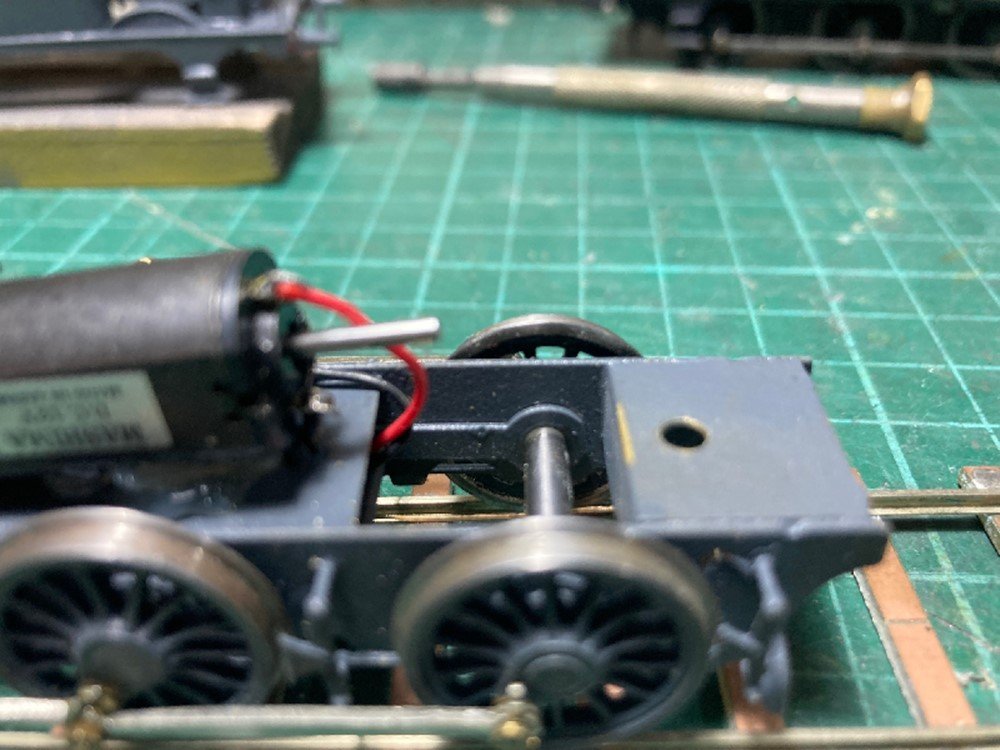
I though it would be useful to post my experiences assembling the SSM (TMD) MGWR E 0-6-0T kit due to recent interest in the kit on the forum. The SSM MGWR 0-6-0T was a relatively early etched kit and a pioneering model as the first Irish 4mm etched kit. The design of the kit has more in common with pressed metal kits such as the Leinster Models O gauge kits, basically a set of scratchbuilders parts to assemble into a locomotive as opposed to the more complex later kits like the SSM/TMD J15 which featured slot and tab assembly, half etched relief detail (rivets, beading), overlay parts and assembly jigs. The kit was originally supplied with a brass chassis with fold up frame spacers etched from the same thickness of metal as the body. The chassis had hornblock cut outs (slots) as opposed to bearing holes which simplified assembling the kit with a sprung or compensated chassis. Some modellers experienced problems with derailments when they assembled the kit with the rigid chassis as the frames twisted when the chassis was bolted to the body at the front and rear frame spacers. The kit was later supplied with an nickel silver chassis which incorporated beam compensation on the leading and driving (middle) axle rather than conventional bearing holes. 553 assembled 1985/6 rebuilt in CIE condition1993. 556 completed 2021. 553 Brass Chassis Sharman wheels 40:1 Sharman gearbox Anchorage DS10 motor 556 N/S Chassis Gibson Wheels, Branchlines 2 Stage Multibox 80:1 state of the art 1985 Motor and gearbox state of art 1990s Sharman wheels no longer available! Underside 553: Chassis compensated all wheelsets removable for maintenance and cleaning, retained by keeperplate/brake pullrods, chassis and keeperplate retained by 8Ba nut and bolt at rear buffer beam only. Chassis is fitted with wiper pick ups which bear on top of wheel thread. Tight clearance between crankpin nuts and valence/steps 21mm gauge. I appear to have replaced the original cast buffers with sprung brass buffers during 1993 re-build. Ideally I should replace Anchorage motor and 40:1 gearbox with a drive train similar to 556 553 top view: Wiper pick ups mounted on PCB sleeper strip largely concealed within sidetanks and splashers (extremely effective). Brass wire behind flywheel retains motor! I have no plans to convert my 21mm gauge steam locos to DCC! having tried it on my T&D 2-6-0Ts its simply not worth the hassle. Keeper plate removed exposing bearings and axle slots. I formed hornblocks from strip brass to prevent the bearings rotating in the slots, the leading and middle axle are free to move up and down in their slots while the rear axle is fixed to provide the 3 point compensation effect. Chassis with leading and central axle removed showing hornblocks and compensation beam. Chassis could do with a strip down and repaint not bad after almost 30 years since last major maintenance. 556 Nickel Silver Chassis. Integral beam suspension leading and middle (driving) axles. Bottom mounted wiper pick up, looks messy but work. I have fitted threaded crankpin bushes to the leading and trailing axles to improve clearance between crankpin and front and rear footsteps, the Gibson OO/EM profile wheels are marginally wider than the Sharman OO/EM profile wheels used on 563. 556 showing compensation beam. The axle holes in the mainframes are slotted and the axles run in top hat bushes that slot through the frames and are soldered to the compensation beams. It was necessary to fit washers between the flange of the axle brushes and main frame to prevent the brush jamming in the axle slots. 556 top view the motor mounting plate is a piece of scrap nickel silver, the motor is bedded in silicone. My preference is to build locos in sub-assemblies with removable wheelsets. The driving axles on the 52 class run in Hi-Level (Kits) hornblocks which are accurate compact and easy to assemble. Modifying the SSM nickel silver chassis to accept hornblocks is likely to be challenging its possible that the High Level J72 chassis may be an option as the overall size of the loco, wheel base, wheel and boiler diameter is very close to the MGWR E Class. https://www.highlevelkits.co.uk/product-page/lner-j72
-
I have assembled the TMD/SSM MGWR E Class kit with both the original brass and more recent nickel silver chassis both locos run reasonably well. I assembled the first kit (my first etched kit) in 1984/5 rebuilt the loco into GSR form about 10 years later and recently completed the second kit. The kit was originally supplied with with an etched brass chassis in the same thickness of material as the body, the kit was later supplied with a etched nickel silver chassis a material which is less flexible than brass. The main drawback with the brass chassis was that it was difficult to achieve reliable running when assembled as a rigid chassis as the chassis tended to twist when both ends of the chassis were bolted to the body and the break gear/pull rods was very fine challenging to assemble, the nickel silver chassis largely over came these problems. The SSM/TMD is a good starting point for assembling etched kits or scratchbuilding, being a very simple kit closer to pressed metal kits such as the Leinster Models O gauge E class than more complex etched kit design. Underside of 553 with brass chassis, showing limited clearance between crank pins and valence in 21mm gauge. I will update my Workbench thread with a post on the pros and cons of assembling both types of chassis. Applying a bit of lateral thinking Andy's suggestion of using a J72 chassis makes sense especially with the High Level Chassis kit https://www.highlevelkits.co.uk/product-page/lner-j72, the two classes are very close dimensionally including overall length, wheelbase, wheel and boiler diameter, a High Level 2 stage gearbox with one of the new coreless motors would result in a very quiet smooth running loco.
- 309 replies
-
- 4
-

-
-

-
- mgwr
- 21mm gauge
- (and 1 more)
-
The ammonia trains were relatively short because of weight. The Irish Railway Models A Class 'Handbook" notes that laden Ammonia trains was very severe on the 001 Class as they were very close to the limit of what a 001 Class could haul up the grade out of Cork.
-
The LMA wagons may survived to the end of loose coupled working in the late 70s, covered wagons used for bagged cement traffic would have become surplus to requirements following the introduction of the Pallet Cement Wagons in 1976, the remaining vans would have been gradually withdrawn as goods trains went over to Liner Train operation between 1976 and 78. There are few published photos of the LMA wagons, there is a photo of 16812 & 17215 at Mullingar in the early 1980s in the IRRS Flickr album. Unfortunately the IRRS was unable to release photos of the LMA and other wagons. I came across the body of 16812 (technically the last of the 1915 design of wagon) on a construction site in Castleknock in the mid 1980s and another at the rear of a farmhouse in Milltown Pass in the late 1990s. Going back to Victor's dilemma: apart from the SSM Convertible and the long discontinued Jeremy Suter Open Wagon & Alphagraphix card kits no suitable kits or rtr models are available of MGWR goods stock from the Edwardian era. The MGWR had a small number of Hard topped 14' Cattle Wagons distinctly different in design to the GSWR, GNR and SLNCR design of cattle wagon, MGWR brake vans were mainly a caboose design with raised cupola and drovers compartment up to the introduction of a 'conventional' shortie design with end balconies but no lookouts during the 1920s. I built an 1874 Brake Van using Evergreen Plasticard and Northeastern Stripwood about 30 years ago a fairly simple scratchbuilding project. Jeremy Suter produced a number of high quality whitemetal kits of Irish wagons during the early 90s including the standard IRCH Covered Wagon, MGWR Open Coal, GNR/NCC Bread Container Wagon and a GNR/UTA Bread Van one off runs which were unfortunately never repeated.
-
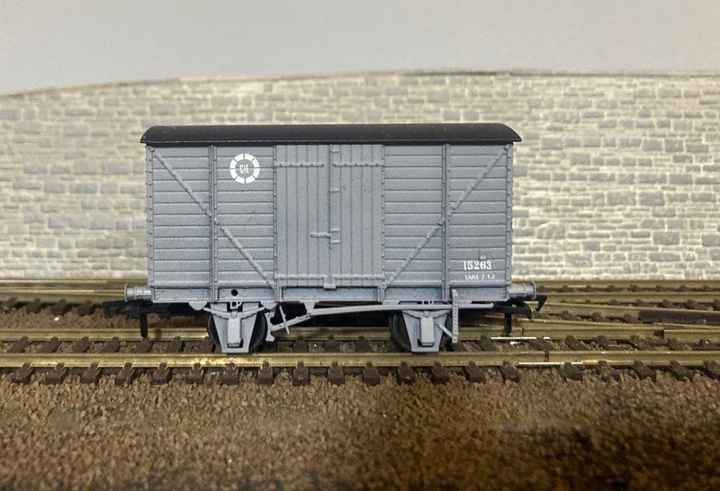
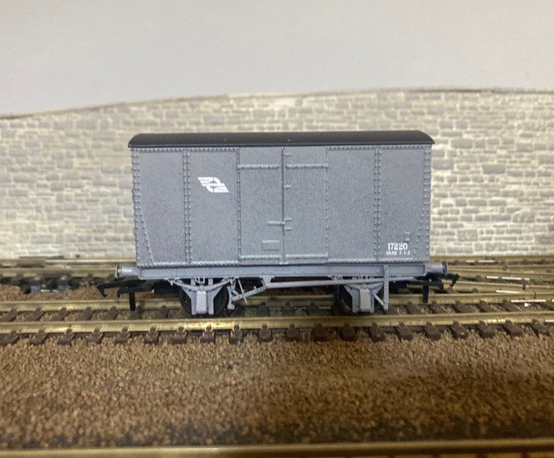
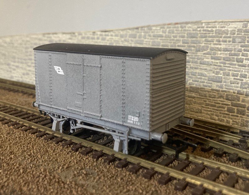
We have largely cleared current backorders and are currently focusing on supplying undecorated wagons. Two new wagons are now available having ironed out some production glitches with the first set of test prints received in 2021. GSWR/GSR/CIE 10T Covered Wagon (planked version). Some of these wagons survived in traffic use until the early 1970s with some later going into departmental use. The LMA Wagon. A very small group of wagons 16812 & 17213-17221 (built 1952) with "light metal alloy bodies" before CIE started churning out large numbers of Plywood Bodies Vans on Bullied Triangulated underframes the classic CIE H Van. Other Wagons: A very small number of decorated Brake Vans, Opens and Covered Wagons are available from the website. https://jmdesignmodelrailways.com/blogs/news/may-2022-update-h-vans-ᴙ-us
-
Some years ago OO Works were looking at the feasibility of a Y Boiler 650 Class and a set of drawings changed hands. The big problem in selecting a suitable "Southern" steam loco for a rtr model is the large number of classes and extent of re-building by the GSR dilutes an already very low level of demand, a GNR loco would be a far more logical choice, single tooling GNR, UTA and CIE liveries. I ended up producing three different versions of the MGWR Ks 650/G2 2-4-0 kit each with different tooling to cover the era from the end of WW1 to the end of steam. No one put their hand up for the original Flyaway Cab version which would have required another tooling. Interestingly 2 of the 3 varieties of the Ks/650 outsold the entire GSWR 52/D17 Class Kit production run. Likewise a rtr model of a MGWR L would require three completely different body toolings to cover the Original, Post 1900 and GSR versions of the same locomotive.
-
I loved the old days when someone phoned (usually from a Call Center in South Asia) claiming there is a problem with our computer or bank account and playing them along till they realised that they had a "false positive" before going totally ballistic shouting and swearing before hanging up. It was pretty obvious that the operators were paid by results and got pissed off with time wasters. These days the scammers use automated phone messages and phising e-mail. Its possible the scammers are harvesting e-mail addresses from posts on social media site or actually buying data from businesses that harvest and sell our personal data for marketing purposes (large social media platforms, banks and postal operators?) https://www.anpost.com/Security#:~:text=Security Hub,help you stay safe online.
-
Probably a co-incidence rather than a security breach at An Post, scammers know that An Post/Customs are collecting vat on almost every parcel that arrives in Ireland which makes it worth setting up Vat and Customs clearance scams. The move to on-line transactions has been a boom for scammers, last year I regularly received scam e-mails from bogus parcel companies, banks and government departments the common thread was a dodgy e-mail address, a demand or an offer of money, within a seemingly authentic looking message.
-

Class 99 electro-diesel locomotive order confirmed for GBRF
Mayner replied to spudfan's topic in Letting off Steam
https://www.stadlerrail.com/en/products/detail-all/eurodual/40/ Stadler is a Swiss owned rolling stock and loco locomotive manufacturer that expended rapidly from the 1990s onwards, their diesel locos appear to be assembled in the former Alstom Valencia Plant based on Caterpillar (EMD) technology. Stadler have developed a series of "standard" locos for use in Europe, Africa and Asian for use on narrow, standard and broad gauge systems with a recent order for New Zealand https://www.railjournal.com/locomotives/kiwirail-awards-stadler-locomotive-framework-agreement/- 1 reply
-
- 1
-
-
Eoin's thread is an excellent step by step in converting the Mainline/Bachmann J72 into a MGWR E GSR/CIE 551/J26 Class. Although the MGWR large and small tanks are similar in general appearance the J72 is closer in size and general proportions to the E/551/J26 Class than the P/610/J10 Class which were larger locos. The new Bachmann model is probably the best option for a OO model, but the SSM kit or a scratchbuild are likely to be the only workable options for a 21mm gauge model, in my experience clearance between crankpins and valences is very tight in 21mm gauge with the SSM kit.
-
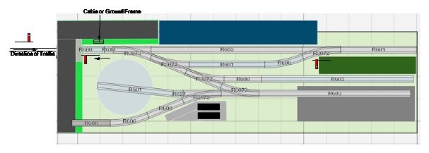
Technically there is no requirement for signals at a terminal station with One Engine in Steam working where the ground frame is locked by the Single Line Staff. I once volunteered as a Guard/Shunter on a UK Heritage line with one train working where all ground frames were locked by the staff, our (fully working) home and starter signals were mainly for show, the main function of the signals indicate to the driver (and fireman) that facing points were correctly set and locked. Traditionally the staff was carried on the loco, with the guard responsible for operating the frame and for controlling the run round/shunting movements. A more flexible arrangement would be for a porter/signalman based at Northport Quay to operate the frame and signals, there is no requirement to lock the frame with a porter/signalman present which would open the prospect of a second train with staff and ticket working or a loco shunting the yard while the Passenger/Mixed is off scene. Valencia Harbour is a good example of a station where the signal box was replaced by a ground frame (worked by the staff?) possibly with One Engine working to and from Cahirciveen during the 1930s A 4 lever frame should be adequate for Northport Quay 1. Down Home, 2 Facing Point Lock 3 Crossover Main line to Loop, 4 Up Starting signal. Movements from the main line to the loop could be controlled by hand signal, with a ground signal to control movements from the loop to main line. The crossover at the pier end of the station is likely to be controlled by weighted point levers or tumblers. Ground frames and working signals was pretty much an optional extra at goods only terminal stations such as Kingscourt and Foynes during the 70s and 80s, points were operated by hand lever or crow bar and padlocked for facing moves by special passenger trains.
-
The 47'6" wagons were introduced exclusively for keg traffic in 1978, beer traffic from Kilkenny and cider from Clonmel were important sources of keg traffic on the Waterford Line until the ending of Liner/Keg Traffic on the Waterford line in the mid 2000s. The cider traffic was transported by road between Clonmel and Kilkenny
-
Signalling requirements depends pretty much on whether the line carries passenger traffic or is goods only. Facing Points on a passenger carrying line (are fitted with locks to prevent accidental movement) and are either controlled by a mechanical Lever Frame or by remotely controlled point motors, fixed signals are usually provided to allow trains to enter the station or access the main line. Points on goods only lines and yards are often controlled by hand levers with no fixed signals, East Wall Dublin is a good example of a yard where all points are controlled by hand, Foynes is another example of a station where points were converted to hand operation after the ending of passenger traffic and the station upgraded to handle Oil, Barytes, Zinc ore and later Fertiliser, Bulk grain and Mollasses traffic. I have marked your layout up with the minimal signalling to handle passenger traffic. The Home signal that controls entry to the station is actually 'offscene" on the other side of the bridge to the station, this signal controls the main line to the station platform up to the buffer stops. I have shown two "starting" or departure signals one at the end of the platform and a second at the bridge before leaving the station though in practice only the latter was likely to have been used in full sized practice. The second starting signal theoretically allows a passenger train an a loco to wait at the platform while a train is departing the goods yard or loop Movements to and from the goods yard/loco depot would have been controlled by had signals from the Signal Man/Shunter rather than by ground signals mainly because of the lack of space. In theory the home signal would have been held at danger and the train brought to a halt, before receiving a hand signal to enter the goods yard. Signals could have been either semaphore or 2 aspect colour light, some stations such as Ballina, Drogheda, Kilkenny, Limerick were re-signalled with colour light signals and power operated points from the 1970s onwards, before entire main line routes were converted to CTC operation during the late 1990s/early 2000s
-
Prices for US stuff in the States tend to work out cheaper including customs charges because retail prices tend to be lower mainly due to the much larger size of the market and greater competition between retailers compared to EU, UK or other countries. Trainworld https://www.trainworld.com/ is one of the larger US retailers that exports World Wide United States Postal Service (USPS) is usually the cheapest option for shipping from the States. Irish vat at 23% is charged on the declared value of the item plus shipping An Post charge a flat processing/clearance fee. Couriers like DHL charge more but offer a faster service. Customs Clearance fees have come down since the Revenue went over to electronic customs clearance DHls charges appear to be based on a minimum charge €10.00 or 2% of the vat if higher
-
Manual uncoupling of Kadee Couplers is quite common among American outline modellers', some people use proprietary tools produced by companies like Rix Products or Kadee, others use tootpicks or interdental brushes https://forum.mrhmag.com/post/maybe-the-best-kadee-uncoupling-tool-for-me-anyway-12298153 Remote uncoupling is not really an issue with an American style Walk-Around layout where the focus is on the operators enjoyment as opposed to producing a visually interesting display for an exhibition.
-
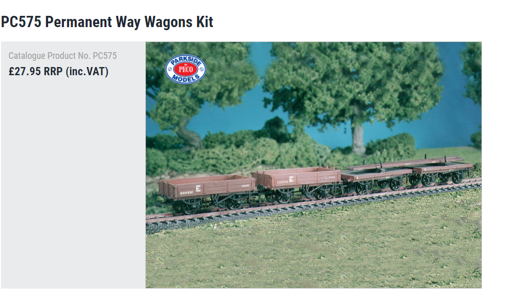
There is a General Arrangement drawing of a 10 Ton "Timber Bolster Truck" in the Compendium of MGWR Non Passenger Coaching Stock and Goods Vehicle Drawings which is available from the Irish Railway Record Society. The 10Ton Timber Bolster Truck is a short 13'8" -8' wheelbase wooden underframe flat wagon which is visually similar to the Single Bolster Wagons in the Peco/Parkside originally PC575 Permanent Way Wagons kit. The kit is good conversion material for Irish Wagons all wagons are supplied with single lever (similar to that used by the Irish companies) in addition to the gear used in mainland UK, the low ballast wagons look similar to those used by the GSWR. The underframe kit (2 sets) is available separately and a good start for scratchbuilt wagons and source of spare "Irish" Brake gear. Peco/Parkside also produce a pair of ex LNWR "Loco/Traffic Coal Wagons from the same source which look reasonably close to older (pre-1917) GSWR/GNR, but not MGWR coal wagons! I built both the PW and Coal Wagons, I will post some photos when/if I can find them.
-
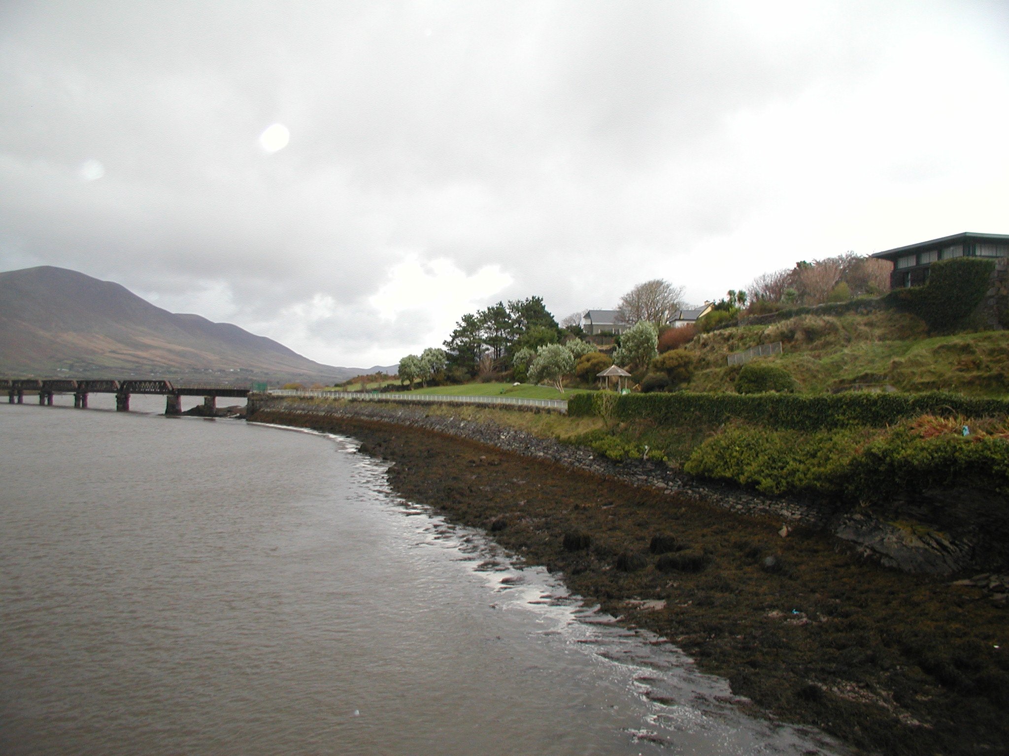
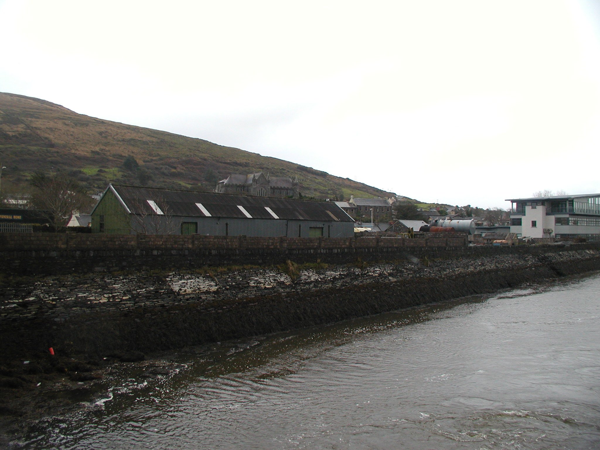
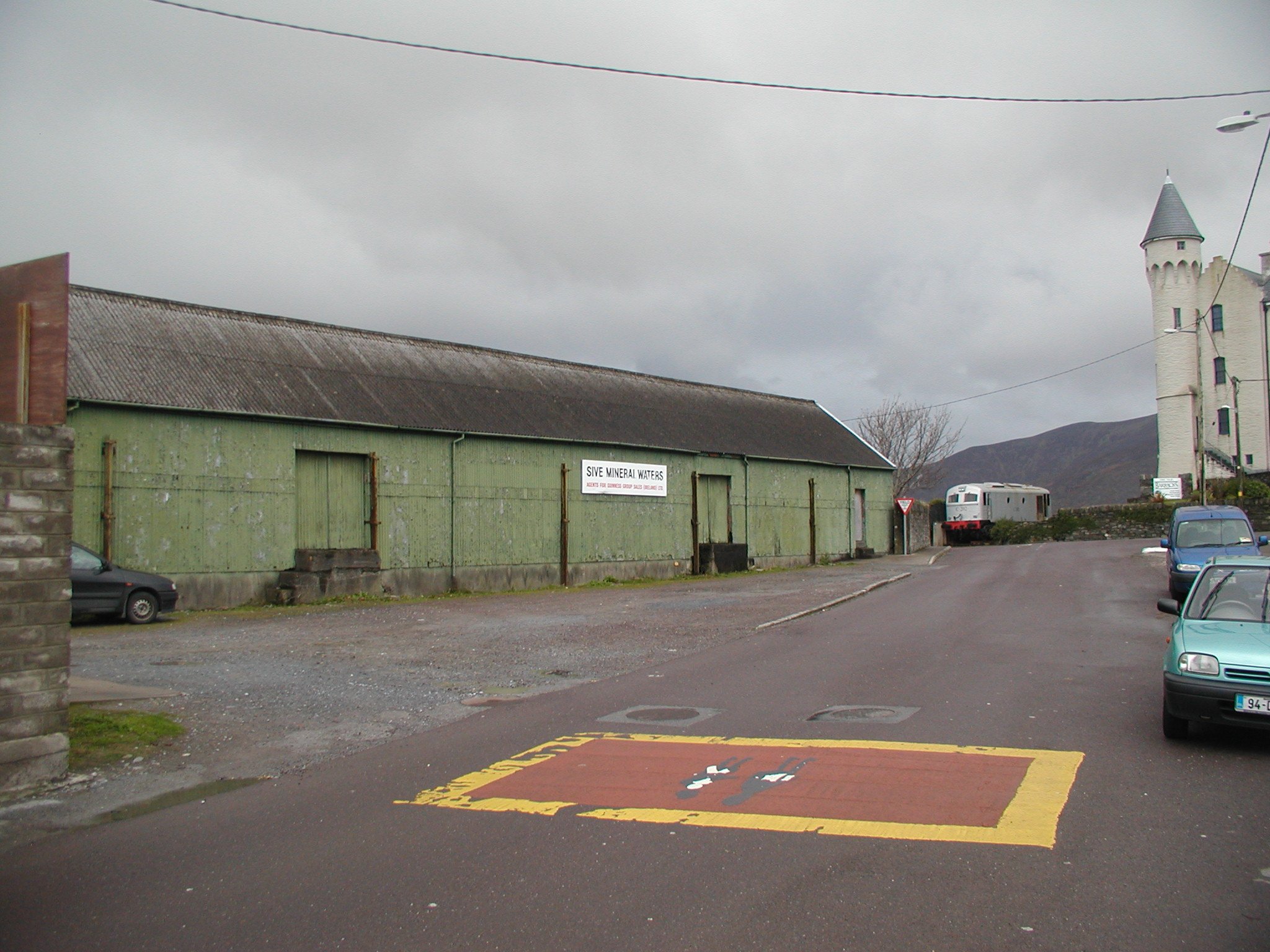
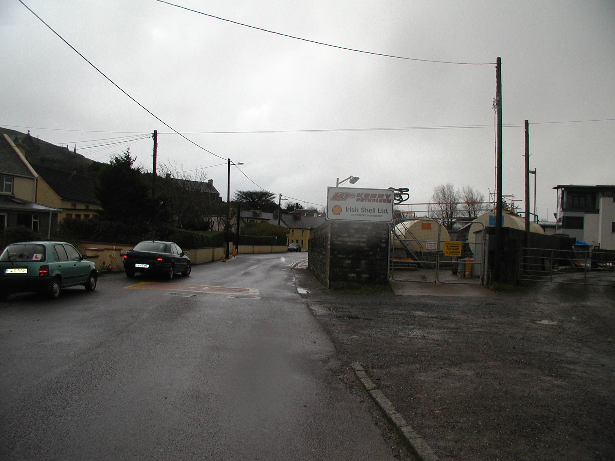
That Larass/Cahirciveen mock up has me mighty tempted though it does not fit in with my MGWR/WLWR interests. The way the goods yard and station is squeezed in between Quay Street and the sea wall makes a visually and operationally attractive model. Interestingly the railway era Goods Shed and Oil Depot were still in use nearly 20 years ago, the Legal Aid Board Offices are on the site of the station building and loco depot.
-
Intended for Electric Train Heating where C Class worked branch passenger trains, most likely Clonakilty, Skibbereen, Birr and Ballina. Largely redundant after CIE closed the Birr Branch and discontinued Manulla Junction-Ballina feeder service in 1963. Apparently CIE converted some (4) older GSR coaches to 'Self Heating' Carriages" by fitting underfloor generators in the 1950s, some Cs were fitted with jumpers for ETH operation as the generators were un-reliable, whether the ETH actually worked on any of these branch line trains is another question. The 'Self Heating" carriages and problems with the generators were reported in Irish Railfans News in the 50s. CIE fitted a Brake Standard and a Park Royal with storage heating when the Ballina Branch passenger trains were re-instated in the early 1970s.
-
I am probably as obsessed about authentic/plausible buildings and structures as JHB is about correct liveries. Wilkinson seems to have operated a major architectural practice from the mid 1830s to the mid 1880s primarily Government work designing Workhouses and Mental Asylums, his railway work seems to have dried up in (as money dried up?) the mid 1860s. The DWWR seems to have run out of money after reaching Enniscorthy in 1863 and did not complete its line to Wexford for another 11 years, Wexford Station is quite humble in nature compared with stations North of Enniscorthy, the DWWR turning to corrugated iron buildings on its New Ross Extension and smaller main line stations.. GNWR (Mayo Line) buildings became increasingly spartan (to keep costs down) as the line progressed westwards from Castlerea to Westport with plain rectangular stone station buildings (originally without canopies), wagons were loaded/loaded outside the goods sheds at Ballyhaunis and Claremorris unlike other major stations on the Mayo Road The most likely scenarios for a railway to Mountbellew are: 1. A locally financed scheme built in the 1860s or 70s taken over by the Midland when the local company ran out of money before or shortly after completion in a similar manner to the Ballaghadereen. One possible scenario is that the line was originally planned as a part of a line from Ballinasloe to Tuam and Ballinrobe to tap traffic from Joyce Country and Mayo rather than a simple dead end branch. It was originally planned to extend the Ballaghdereen line to connect with the Mayo Line at Castlerea to tap into cattle traffic from the plains of Galway and Roscommon. Spartan possibly Gothic buildings like Ballaghadereen, Ballymoe, Donamon (Mayo Line) or plain rectangular buildings (Clastlerea-Westport) 2. A Baronially Guaranteed Light Railway to Mountbellew built in the 1880s/90s similar in character to the Loughrea, Ballinrobe, Branches but with the station buildings and goods shed on a smaller scale. Its possible the Midland might have adapted the "English Cottage" style of architecture used on the Western Extensions if the line was built in the mid-late 1890s, the MGWR used this style of architecture at Ballyvary Station on the Ballina Branch http://eiretrains.com/Photo_Gallery/Railway Stations B/Ballyvary/IrishRailwayStations.html#Ballyvary_20040704_0003_CC.jpg A Baronial Guaranteed scheme would have had a greater chance of success than an 1860s/70s scheme as the company shareholders had a guaranteed return on capital and the County Council could take over and work the line if the project failed like to Tralee and Dingle and Schull and Skibbereen In the end anything is possible/dooable!
-
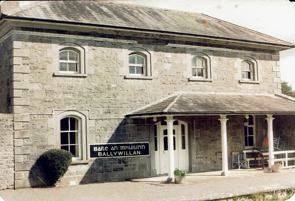
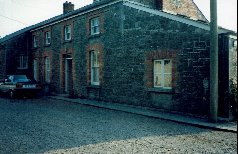
The other point to consider is that there was no longer a need for impressive architecture (to demonstrate the railway was a good investment) once the MGWR completed its trunk routes by the 1860s, the company preferred to sit back and let local companies or the Government take on the risk of building branch lines and secondary routes. Apart from the Great Northern and Western (Athlone-Westport & Ballina) the majority of these companies struggled to raise capital and cover their operating expenses, buildings tended to be plain in nature built from local materials generally coursed random stonework with brick rather than stone quoins and detailing used in earlier construction. Ballywillan Cavan Branch, stone quoins and detailing. Athboy brick quoins and detailing window and door openings, brick chimneys. Its likely that Mount Bellew station buildings would have been close in scale to Athboy, Kingscourt or Killeshandra as they were similar sized towns in the late 1800s, Loughrea and Ballinrobe are considerably larger towns.
-
Not strictly speaking the MGWR engaged firms of Architects and Engineers to design the buildings and structures on its Main Line and Sligo/Cavan Branches, its likely that the railway would have set out its requirements in terms of floor area and office/station accommodation. The same principal would have applied to lines built by worked companies like Loughrea, Ballinrobe and the Western Extensions, the MGWR seems to have developed its own standard designs for (brick) platform shelters and small goods sheds (Attymon) during the late 1890s early 1900s. The MGWR engaged different firms of Architects to design the buildings on the Dublin-Galway (G.W. Hermes) and Mullingar-Sligo-Cavan Lines (George Wilkinson). There was a lot more variation in design between station buildings on the Galway Line and Sligo/Cavan Branches. The Main Line was completed between 1847 & 51 and Sligo/Cavan between 1855 and 62, in the early days the company may have been more open to outside pressure than 10 years later. The Trench family at Garbally Park and Woodlawn House no doubt had an influence on Ballinasloe and Woodlawn Gothic station building and Goods Shed design Wilkinson was also engaged by the Dublin, Wicklow and Western (Harcourt St-Enniscorthy) and Great Southern and Western (Clara-Athlone and Nenagh, there is a stong "family" likeness between Wilkinson's station buildings and goods shed built for all three railway companies, including semi and circular good shed windows. Station buildings and goods sheds at stations like Athboy, Ballinrobe, Loughrea and Kingscourt are likely to have been designed locally as oppose to a detail design prepared by the MGWR.
-
Better still the Irish 3' gauge on 15mm on 45mm gauge track! A lot of Neil Ramsey's signal cabin is pure Lough Swilly I think John Campbell a prolific builder of Irish live steam locos built both a Swilly 4-8-0 and 4-8-4T

.JPG.b3bdcf77c7cf1e6be499cb5677cb2898.JPG)