Mayner
-
Posts
5,086 -
Joined
-
Last visited
-
Days Won
126
Content Type
Profiles
Forums
Events
Gallery
Blogs
Everything posted by Mayner
-
CIE stopped using MK2D stock on the Enterprise after the train was de-railed as a result of an attack on the line near Lisburn in the mid 1970s. There is a photo of the de-railed train in an IRRS Journal from the period, coaches remained coupled and upright, I don't know if the de-railment was as a result of a hi-jacking or a bomb being detonated under the train. Conventional stock was also more operationally convenient for CIE as there seems to be enough Craven, Park Royals and Laminates to strengthen trains to meet seasonal demand while availability of MK2d stock was tight, the 1970s MK2D Enterprise seems to have typically loaded to 5-6 coaches including van. I prefer the original Maroon & Blue scheme since I first saw the train in Connolly station in 70/71 and later used to listen to and watch the evening North bound Enterprise climbing towards Killester from Collins Ave while waiting on the bus home from work for most of 78-79.
-

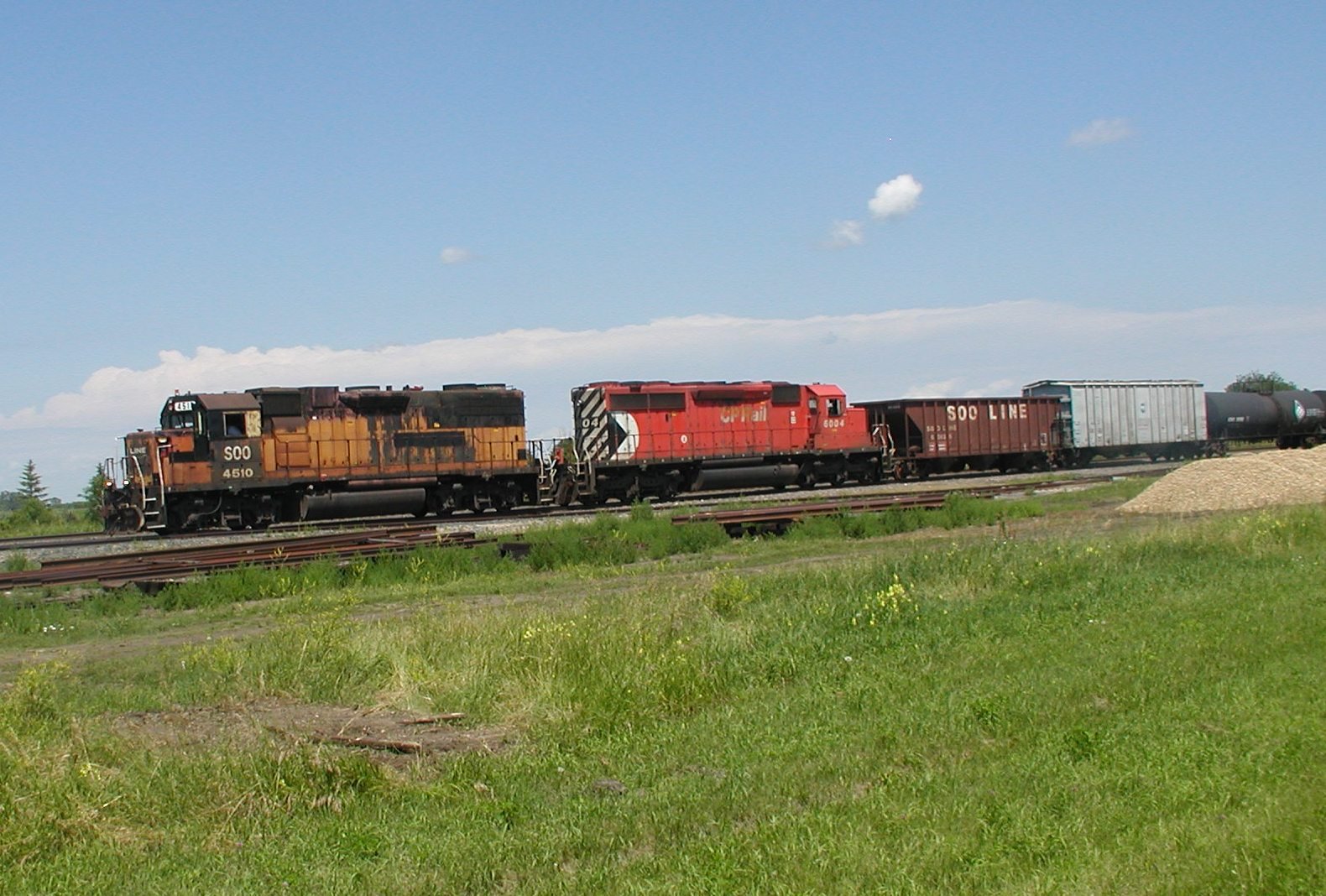
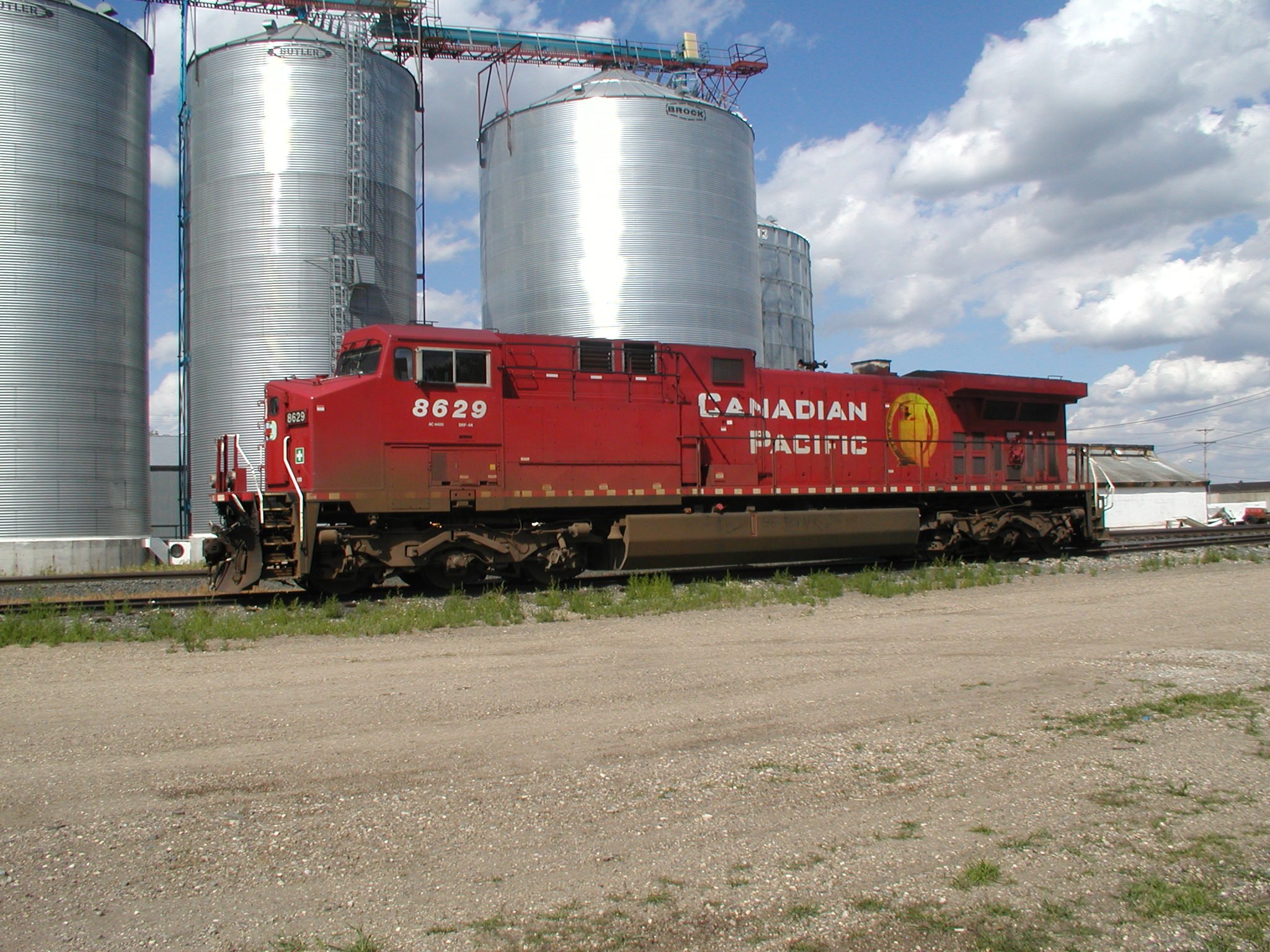
Avonlea Sun Loco service facility. CP Rail
Mayner replied to NIRCLASS80's topic in US / Canadian Railway Modelling
Interesting to see models of SOO ex-Milwaukee Road Bandits I came across an ex Milwaukee "Bandit" GP38-2 but did not realise what it was while visiting relative in North Dakota in 2004. While most of the through trains were hauled by relatively new GE power in the CP Beaver scheme, way freights were worked by locos in CP Pacman & SOO line branding.
-
While Irish Rail were a lot more pro-active than CIE in terms of pursuing both passenger and freight traffic, the rail system became increasingly un-reliable and close to a state of collapse (breakdowns, derailments, extended journey times) as a result of the run down nature of the infrastructure during the 1990s. 1900-1914 is probably the closest to a "Golden Era" in terms of Irish Railways both in terms of sheer variety, standard of service and standard of maintenance of equipment and infrastructure. IE in the 90s and early 2000s is an ideal period for modelling a run down railway with weathered locos and stock and poorly maintained track, signalling and infrastructure The "Big Companies" (GSWR, GNR, BNCR (NCC) and MGWR) were prosperous even by UK standards, all introduced large modern locomotives and bogie stock with dining car service for main line services (all in distinctive liveries) during the early 1900s. IE was still attempting to run main line service on track laid by the GSWR,GNR & Midland 70-90 years later!
-
Arup to undertake all-Ireland rail review
Mayner replied to spudfan's topic in What's happening on the network?
It looks like a logical follow on from the "Irish Strategic Rail Review'' Booz Hamilton 2001 which marked a major change in Irish Government thinking which had previously focused on the losses made by CIE/IE rail services with no long term planning to retain and develop the existing rail network let alone develop new services. The future of rail in Ireland was in doubt during the 1990s with both the IE & NIR systems approaching the point of collapse, there was little Irish Government commitment to maintaining or developing rail services, overdue track renewals and improvements such as the Arrow & revived Enterprise were largely dependent on EU funding. The Irish Government had implemented a policy on no major investment in rail (with the exception of completing the Cork Line CTC and MK3 Intercity Coach projects) under the Building on Reality" programme of the 1980s, this policy was not finally reversed until the Government implemented some of the recommendations of the review which lead to the loosening of the purse strings and a shift to a Commuter and Intercity passenger railway with major investment in new rolling stock, infrastructure renewals which lead to more frequent train services. -
There are/were two Clonmacnoise & West Offaly "trains" coaches. The Blackwater Operation catered mainly for Coach Tours and added a second train (Coach) after several years successful operation. The project and Blackwater Museum was set up on the initiative of redundant BNM staff in the late 80s and seems to have been financially successful. the Tourist Train Operation was shut down after the new Shannon Bridge Power Station came on line and BNM fuel peat rail operations became extremely busy. I visited Blackwater in the early 90s both Tourist and Fuel Peat operations were busy with Milled Peat Trains queuing behind the 'passenger" line of sight operation. Interestingly Blackwater staff were proud of their operation and had visited several of the Welsh Narrow Gauge Lines while planning the West Offaly operation. By contrast I was the only passenger when I visited the Bellacorick railway and staff not exactly enthusiastic. The rolling stock at Bellacorick was more interesting from an enthusiasts perspective, the passenger portion of an ex-West Clare diesel railcar and a unique BNM rebuild of a RH diesel, but less attractive to the casual visitor or Coach Tour participant.
-
Definitely fits in the "Now for Something Completely Different" modelling category. The Lartigue loco looks really well in lined blue.
-
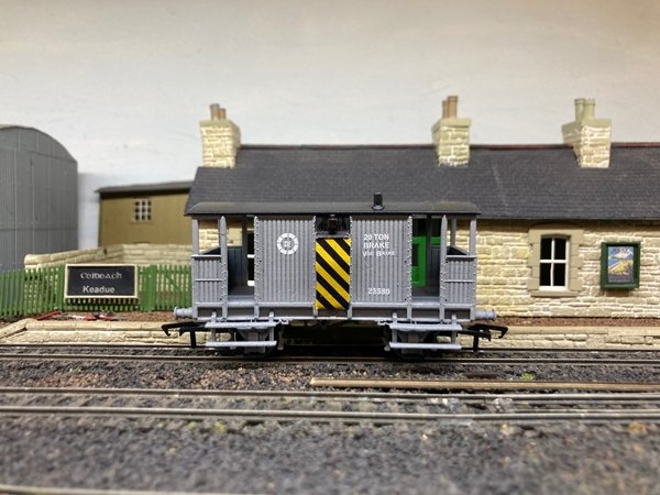
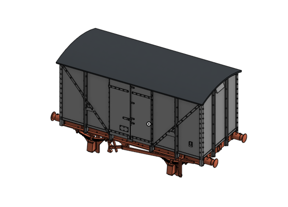
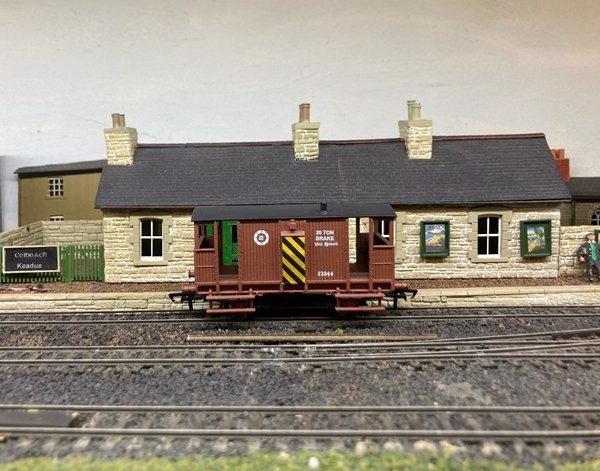
RTR wagons. We completed the decorated sample of 23544 & 23580 20T Brake Vans with post 1963 wheel logo for delivery Sep-Oct 2021. We are using waterslide (Railtec) transfers for these vans rather than pad printing used for our "Flying Snail' vans due to the relatively low numbers involved and challenges in forming the wasp stripes using pad printing. We are currently examining the option of dry print transfers as an alternative to waterslide for the Bulk Grain Wagon and other future models. Future models: Our designer is currently working on the original GSWR/GSR (planked)and early CIE (metal sheeted) versions of the standard covered H wagon. Loco and Coach Kits. The 52 Class Locomotive kits are sold out and have been shipped to customers. The parts are in stock and we expect to ship the Heating and Luggage, Luggage Van and Post Office/Tool Van kits to customers during September and October 2021. While the majority of these kits are pre-sold a number of these kits will be available for sale on the website.https://jmdesignmodelrailways.com/
-
The Nenagh Branch trains appear to have been the main 001 plus Craven passenger working in IE days, 001s were regularly used on Intercity diagrams with MK2D stock (Supertrain) on the Heuston-Waterford (early afternoon Heuston-Waterford and return) Connolly-Rosslare intercity trains and occasional CIE Enterprise working during the late 8os early 1990s. The Limerick-Ballybrophy was sometimes a 001 Class, Single Craven and BR van.
-
The protective guards were fitted to 001 Class locos which received overhauls (which included a repaint) at Inchacore in the early 1990s, CAWS equipment was fitted to all main line locos by 1984 in order to run over the electrified lines in the Dublin area.
-
The 3 car BUT Railcar Set and 4w Hooded Van may be at Macmine Junction. There is a 1962 John Langford photo of a similar(possibly the same set) in the Waterford platform on what appears to be a southbound working with a Green 901 Class car leading, Cream and Blue ex-GNR Brake 3rd and Black and Tan 701 Class car trailing hauling what looks like a Black and Tan 4w PO van. There also appears to be a connecting train in the Waterford Platform in the H C A Beaumount photo Its possible the Railcars are exchanging Mail Traffic with a Wexford-Waterford passenger, during its final years most North Wexford passenger trains appear to have ran with 2 4w Hooded Vans and a single coach. The ex-GNR BK 3nd appears to have been re-built by NIR with new windows with rounded corners and new body paneling. Modern GNR flush sided stock were originally built with windows with square corners similar to the BUT and AEC railcars, this lead to problems with leaks and decayed (wooden) body framing especially on coaches built during WW11 which apparently had hardboard rather than steel body panels.
-
Vat is liable on the total value of a shipment including freight not just the declared value of the goods, international shipping is zero rated for GST so there is no element of double taxation. Hatton's probably claim the excess VAT as an expense when they reimburse a EU customer for vat charged by an Post on a tax paid item. Using a EU Intermediary or customs agent is likely to be prohibitively expensive for low value (<€150) shipments, one of the major international postal/express companies quoted a $40 DDTP processing fee for each package shipped to the EU regardless of value. Interestingly individual packages shipped using a DDTP service are delivered by Courier or Express companies rather than the Postal Service and shipped without a customs declaration or label on the box. We printed labels for test DDTP shipments to customers in the UK using NZ Posts on-line system, interestingly labels were domestic UK using a UK Courier Company rather than an international parcel label with customs declaration. I guess the main lesson is that modelers importing from outside of the EU can expect to pay higher prices for models including customs processing charges or limit their purchases to what's available in Irish model shops.
-
Unfortunately its not simply a matter of non-EU resident companies like Hattons registering for Irish/EU vat, paying the tax and putting a tax paid label on the box, they are also required to either have a physical presence in the EU or use an EU customs agent or intermediary. https://ec.europa.eu/taxation_customs/modernising-vat-cross-border-e-commerce_en JM Design registered for Irish vat & an EORI number in March in order to export tax and duty paid to Ireland and the EU. We currently export to the EU at 0%Vat as we could not guarantee that our customers would not be hit with VAT & admin charges at the point of entry. The Revenue Commissioners were unable to provide guidance on the declaration and clearance process and our preferred shipper is currently unable to offer a delivery duty and tax paid service to the EU despite announcing the service in January 2021. In practice it will probably be cheaper select shipment from the UK by a mail service and pay the vat on arrival than a Courier or Delivery Duty and Tax Paid service. An Post €3.50 service fee is cheap compared to customs clearance charges for individual DDTP packages.
-
The ex-BR "Vans" http://silverfoxmodels.co.uk/ir-ie-generating-steam-van-ex-br-mk1-bsk/ is probably the best option for a van for TL fitted Cravens. The "Dutch Vans" were less common (6) compared to the larger number (22) of ex-BR Vans The Cravens were used almost exclusively on main line Intercity services until some were "cascaded" onto Outer Suburban and Secondary Passenger services following the introduction of the MK3 Stock from 1983 onwards. Typical main line TL sets were usually made up of a "BR Van" "1951-53 Buffer Car and several Craven Coaches, TL fitted Park Royal & Laminate coaches were sometimes used to strengthen main line rakes.
-
Munster Simms appears to have been a fairly large oil distributor during the 1930s with both Belfast and Dublin registered wagon fleets. A number of photos of Irish registered tank wagons in the HMRSI Charles Roberts Collection. https://hmrs.org.uk/photographs/munster-simms-belfast-motor-spirit-14t-tank-no-2-order-942.html. https://hmrs.org.uk/photographs/munster-simms-dublin-14t-tank-wagon-no-4.html.
-
One of the challenges of building an Irish Broad Gauge steam locomotive in OO gauge! On the majority of outside cylinder steam locos the conrods are on the outside of the coupling rods but not on some outside cylinder 4-4-0 classes including the GNR Compounds and Metropolitan 4-4-0T. It basically leaves the builder with the choice of cranking the coupling rods to avoid running problems or fitting the conrods on the outside of the connecting rods and using a longer crank pin bush.
-
Nice to see the subtle weathering of the Tin Van it must be 5-6 years since they left the Carriage Shops in ex-works condition! The open un-cluttered nature of the place with no goods shed or station building reminds me of Fenit which I first visited in the summer of 78 several months after the last train (beet special)departed. Have lots of fun!
-
One of my favourite might have been scenarios was a "joint" MGWR-GNR line from Kells to Cavan via Virginia and possibly onwards to Enniskillen a better routing for Dublin-Cavan & possibly Monaghan passenger services than by Inny Junction. An amalgamation between the Midland and the Great Northern was actually considered in the early 1920s with the LMS taking over the lines north and west of Dublin and the GWR taking over the GSWR, DSER and West Cork.
-
Interesting both MGWR signs, the Inny Junction one is particularly interesting including Clones Junction a destination on the Great Northern. There were no advertised connections between the Midland & GNR at Cavan in the 1897 MGWR WTT, though there are advertised connections are advertised between Navan Junction and Kells but not Oldcastle in the same timetable. The MGWR had running powers over the GNR between Navan & Kells possible reason for the connection. In pre-amalgamation point Cavan was a major interchange point for cattle traffic from the Midlands to Belfast Port with trains working through between the two systems, presumably with loco change at Cavan or possibly Clones?
-
Would you model in 21mm if RTR track and models were readily available?
Mayner replied to BosKonay's topic in Irish Models
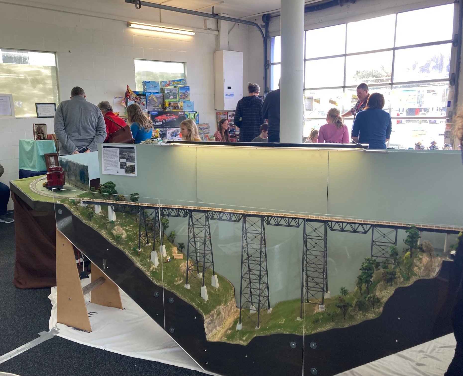
There are simpler & quicker ways to handlay track than using slide on plastic or 3D printed chairs or solder the rails to every sleeper! Main Trunk tall steel viaduct scene with handlaid track on viaduct assembled using "Micro Engineers" parts. S Scale NZR 3'6" gauge track (OO) with copper clad sleeper every 5th sleeper spacing, missing sleepers will be fitted using stripwood sleepers. Some NZR 3'6" gauge layouts use Peco or Atlas for hidden trackage and handlaid track in scenic areas. Viaduct scene took 18 months to construct. Layout was exhibited this weekend at Whitianga Train Show first time I have been to an exhibition in a long time! I am planning to use spiked track for a planned 21mm gauge layout using stripwood sleepers spiked every 5th sleeper with soldered crossing wing rail assemblies.
-
The Australian 3'6" gauge Metrovicks (WAGR X & XA Class) retained their Crossley engines to the end 1988 working narrow gauge Perth Suburban trains until services were electrified, few clouds of dirty smoke unlike the CIE engines.
-
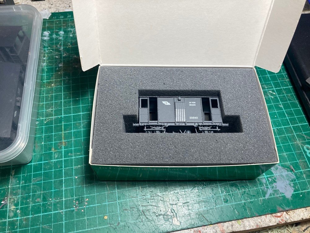
The first production batch of brake vans is substantially smaller than originally planned as a result of issues at the 3D printing stage which did not show up at the prototyping and test print stage. A small batch of 1950s vans is currently with our tampo printers waiting a slot in his production schedule. I am expecting to release the 1960/70s versions of the vans which are currently in the paint shop during September with transfer lettering as it would have been uneconomic to reproduce the ducket warning stripes using tampo printing. Pre-orders provides a reasonably accurate estimate of demand which will allow batch quantities to be increased/decreased as necessary. 23543 was lettered using tampo printing, alternative numbers would require a new printing tool and separate set up prohibitively expensive on small batch quantities. We are planning to finish the Ranks grain wagon with transfer lettering with running numbers (1-8) which may be applied by the customer (running numbers). We are not expecting to release the open wagons until the 1st quarter of 2022 and will certainly consider releasing these and other 'ordinary' goods wagons in fully decorated form with alternate running numbers or unlettered with a sheet of transfer lettering. Our 3D printing bureau is currently completing a number of test prints of the grain wagon to establish a representative sample of prints to identify potential production and quality assurance issues before we produce the production batch, we have also bought a high resolution desktop printer for prototyping and small batch production with a larger production machine expected late 2021 early 2022 which will give us greater control and predictability of our production schedules. I would forget speculating on our wagons we can always produce a batch of a particular wagon with minimal tooling and set up cost if there is evidence of sufficient demand.
-
The models can be ordered/pre-ordered on our on-line shop https://jmdesignmodelrailways.com/. The first batch of Brake Vans in the 1950s grey are now sold out, the second batch (50s Grey)are currently with our tampo printers & we will start accepting orders once they are complete and assembled.
-
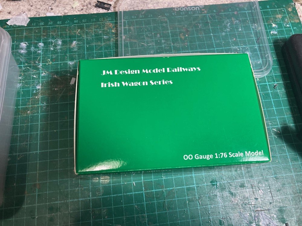
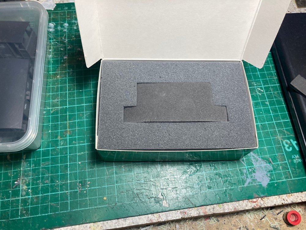
Generally 2-3 weeks at the moment, recently an Airmail package from Markits arrived within 7 days and one from Wizard Models took 4 weeks. Van is packed in a presentation box within a stout cardboard shipping box with foam or bubble wrap packing. Packaging was a challenge as the traditional model railway style box with lid were unavailable and a vacuum formed insert prohibitively expensive, we used a medium density foam rubber to secure and protect the model. so should be ok.
- 58 replies
-
- 13
-

-

-

-
Would you model in 21mm if RTR track and models were readily available?
Mayner replied to BosKonay's topic in Irish Models
One significant point if you intend to 3D print track and point bases Templot uses two different gauges for modelling Irish 5'3" track in 4mm scale. 21mm gauge for P4 standards and 20.2mm if you use EMF or OO gauge standards, Martyn Wynne did much the same to achieve improved running with rtr OO rtr rolling stock reducing the gauge from 16.5mm to 16.2mm or EM-2. I struggled with Templot for a small EM gauge layout and have gone back to blown up EM gauge paper templates for 21mm gauge track. 3D printed point-bases are likely to be challenging particularly if there is no provision for adjustment in the location of crossing vee and switch assemblies. Personally I have hand laid pointwork in 1:1, 1:24 and 1:76 scales using timber, copper clad and ABS sleepers, using fangbolts, spikes, and individual chairs and soldered assembly and did not find it particularly difficult or time consuming, the main difference was that I needed a lot more people and machinery in 1:1. Chaired assembly either slide on or individually placed is a lot more time consuming and technically challenging than spiked or soldered assembly. -
Complete with what looks like a solid rake of "Silver Princes" stainless steel coaches As they say paper never refuses ink or electrons to get excited!