murrayec
-
Posts
2,726 -
Joined
-
Last visited
-
Days Won
70
Content Type
Profiles
Forums
Events
Gallery
Blogs
Store
Community Map
Everything posted by murrayec
-
By the photos it would seem to be missing parts- valve gear and cylinder parts! also other kits from this seller are also missing parts... Eoin
-

Bing Live Steam Loco Gauge O - Repair & Restoration
murrayec replied to murrayec's topic in ECM Model Trains
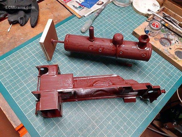
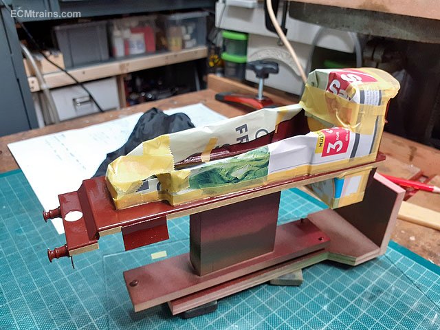
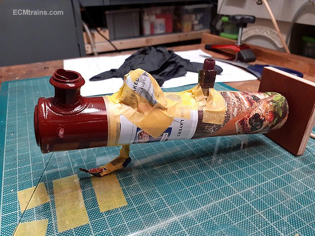
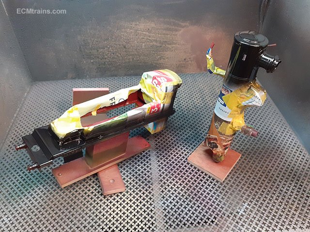
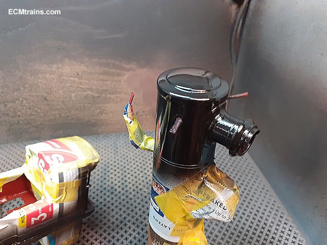
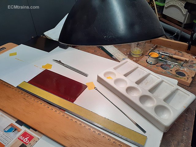
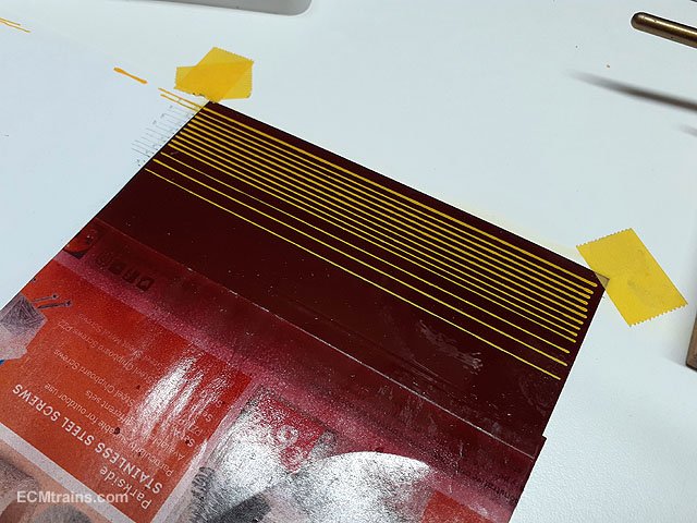
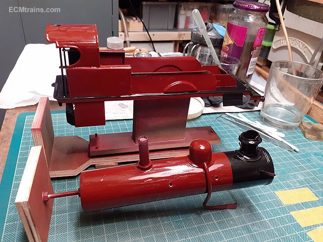
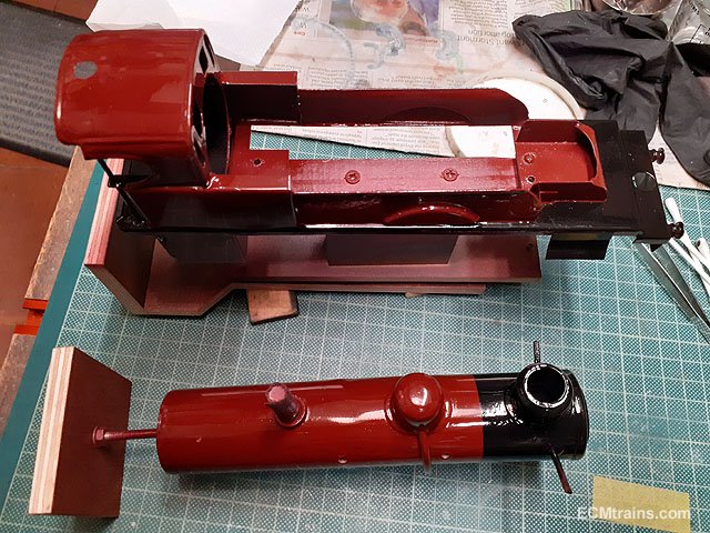
The first coats of brown did not go on to well, the paint just refused to flatten out when drying! so gave it a good week to dry and then out with the wet n dry and rubbed it down all over. The next few coats went on beautifully- flattened out n all shiny. Next was the masking up for the black paint on the running boards, cab floor, and the smokebox on the boiler. Black on. I got a good wet coat on after spraying a light tacky coat and leaving it for 45mins before applying the wet coat. And unmasked. I set up a decal sheet for doing the boiler bands and some of the lining, I sprayed a base coat of the brown colour onto Testors transparent decal sheet but the paint did not take to it very well, finger prints and greasy areas caused the paint to run away! When that coat dried I washed it down with white spirit and sprayed it again, I ended up with a very poor surface for running a bow pen on which is what I'm going to use to do the lining. I decided that this was going to be a practice sheet and would order new and better paper, so in the mean time I had a go... I strapped the decal sheet to a bit of white board, using a T-Square and a heavy ruler with masking tape stuck to the underside so the ruler stood off the sheet. I did a few yellow test lines using a guide sheet there on the left with the line positions marked out in pencil, as suspected there was to much undulation in the base paint the lines came out different thickness over the length. Not happy with this so will wait for the new paper. I did the black paint between a few of the top yellow lines for the boiler bands but it was disastrous and not going to show you! Chassis and wheel painting is complete and the chassis is now back together. So nearly there...... Eoin
- 24 replies
-
- 6
-

-
- bing live steam
- bing gauge o
- (and 1 more)
-
Hi JB Some have used RAL 7015 which is a pretty close match, Eoin
-
I use all kinds of insulation for baseboards, see at this link;- Eoin
-
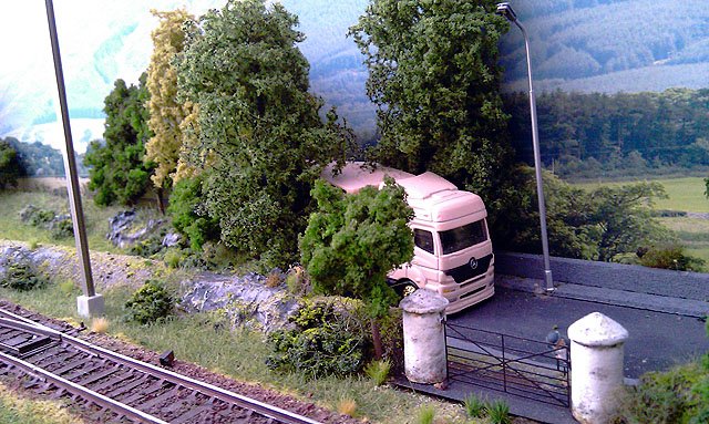
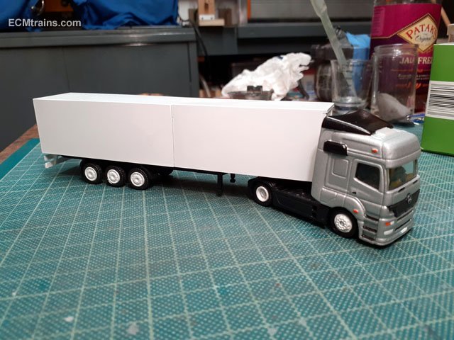
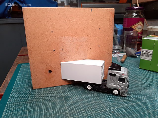
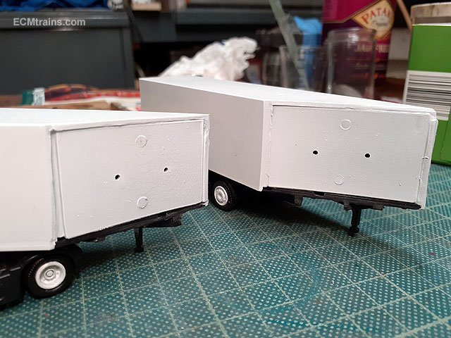
That back-scene pink truck got a make over in the paint shop;- A bit of silver black on the truck, gloss white on the trailer, and gloss white on the 'Gold' wheels. This is the set-up for that view of the truck coming out of the trees, the trailer is cut at the appropriate angle and dept, and the trees mask off the view to the missing end. After cutting the trailer styrene ends were installed with 3mm dia magnets to stick the end back on if one decides to locate the truck n trailer elsewhere on the layout. Eoin
-
until
-
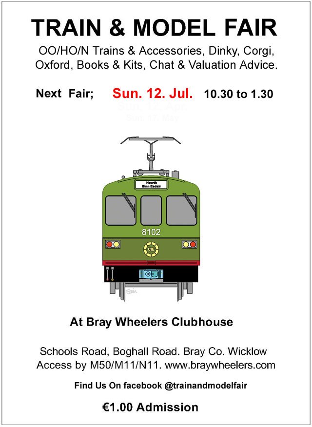
The Train & Model Fair is back in business, here is the date for July;-
-
I live on a country lane which sees a fair share of horses, more than occasionally they leave deposits on the road outside my place! Luckily there is a lady that does roses up the lane, so I give her a call and she's down in an instant cloves, willies n bucket..... Eoin
-
Scrawker Mod;- 3mm mdf handle epoxied to both sides of the blade- doesn't hurt the fingers any-more. Eoin
-
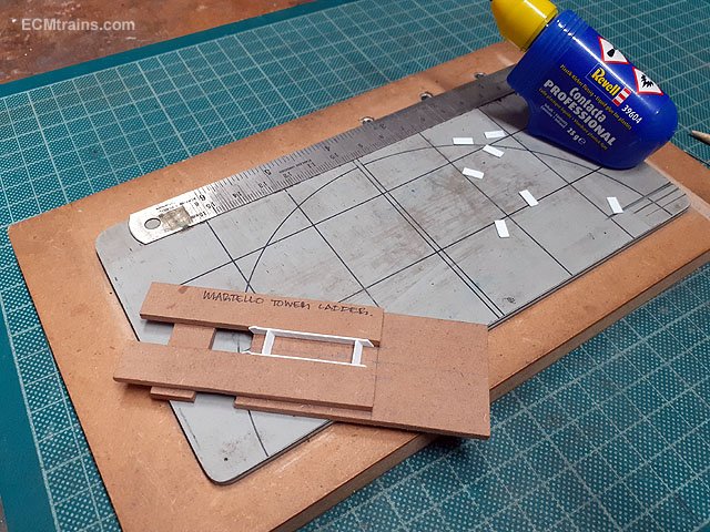
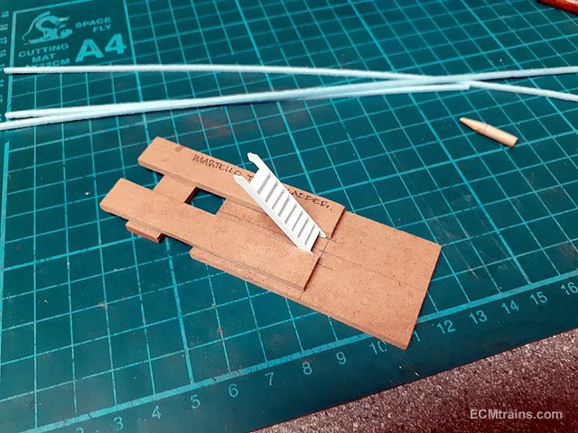
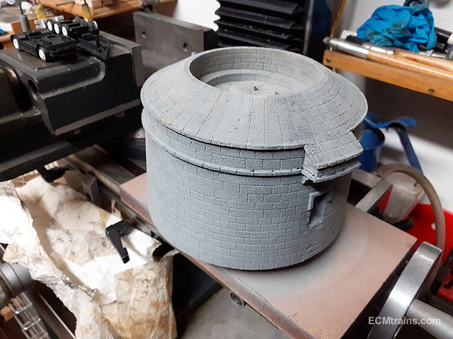
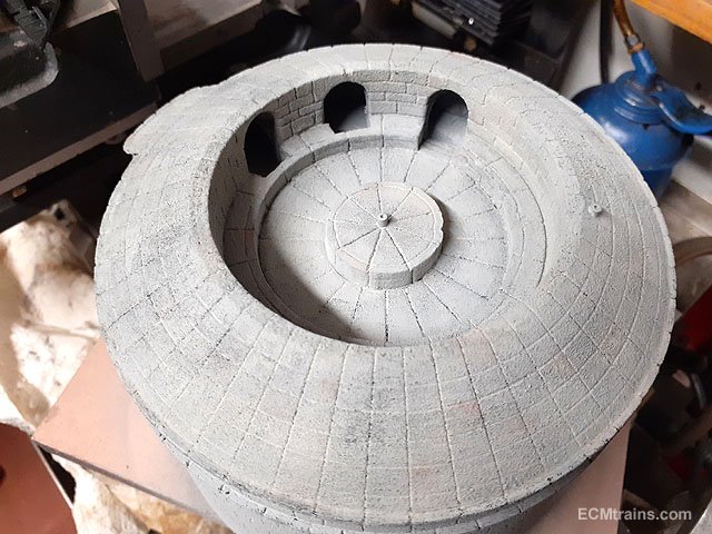
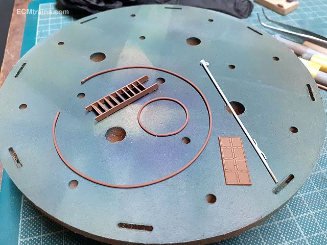
Making the steps/ladder for the Martello Tower is a bit fiddly so I made a mdf jig to hold the styrene side strings in place while gluing the threads in. Done. Starting to paint the tower. After a number of coats of Humbrol 1 I washed it down with a dilute black wash and now hopefully the next step is a light translucent coat of very light grey to finish off?? Racers, steps, door and flagpole all painted and awaiting instillation. I gave up on the flat styrene racers featured above, with the stone scoring I decided to use .8mm piano wire for the racers which will be glued in after the stonework is painted. I also made up a flag pole from .8mm brass rod with a hoop and cleat from .4mm brass soldered on, the pole cap is a bit of styrene tube glued on. Eoin
-
@Noel I would recommend using epoxy glue for resin mouldings, the main structure done complete with epoxy, one could use Rocket 5-10 (it's stronger but does bloom if one uses to much) to assemble small parts and then apply epoxy to reinforce. Cyano does not suffer shock well and bits are liable to spring off.... The insides of these wagons would not have been painted so if thinking of painting a wood colour would be the one...... The doors were right down to the floor and the ramp closed up against them which locked them shut..... Eoin
-
Bing Live Steam Loco Gauge O - Repair & Restoration
murrayec replied to murrayec's topic in ECM Model Trains
@Midland Man yes pretty sad- I heard that the chap who built it- his family from the UK came visiting and asked could they call to the house to view the layout as it was their father's pride & joy, they were very disappointed when they saw the track in it's over-grown state. I will be building a 3.5" straight track in my garden to run the Northumbrian loco when complete, I may invite the now owners of the track to come and view it running and that may light a spark!! Eoin- 24 replies
-
- 4
-
-
- bing live steam
- bing gauge o
- (and 1 more)
-
@airfixfan you may have this already- Ernie Shepard's book 'Bulleid And The Turf Burner And Other Experiments With Irish Steam Traction' by KRB Publishing ISBN 0954203585. Eoin
-
@popeye here is a link to SSM's OO kit built sporting the 800 green;- Also a link to Ian Rathbone's recent paint job on a SSM GSR 800 OO kit of which I enquired with him the colour mix he used;- https://www.rmweb.co.uk/community/index.php?/topic/152458-gsr-800-class/&do=findComment&comment=3942064 Eoin
-
Looking great David. Your point about the thinness of the smokebox;- I notice the front sand boxes in the prototype photo are higher off the splasher and butt up under the side curve of the smokebox, where the model has much lower boxes exposing more of the smokebox vertical side, making it look thinner! One could add an extension to raise the sand boxes and fill in the gap? When the front angle piece under the smokebox door that covers the front of the saddle goes in- this will beef things up a bit? Eoin
-
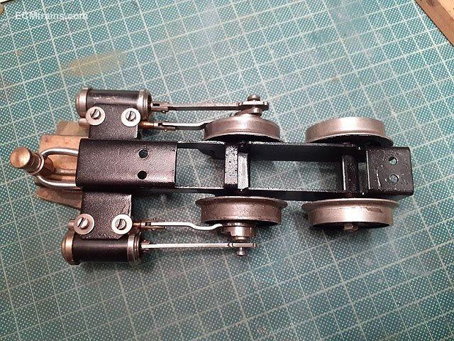
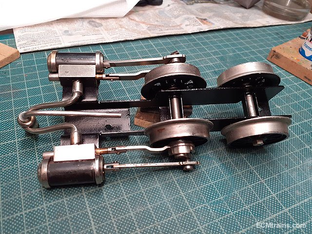
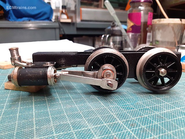
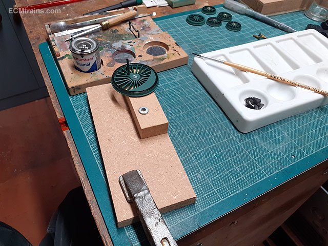
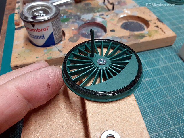
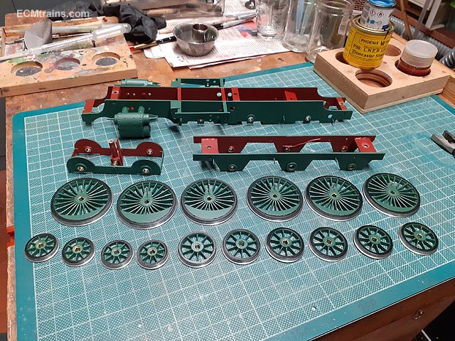
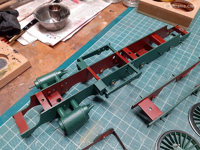
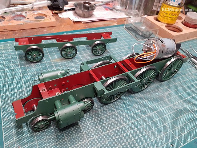
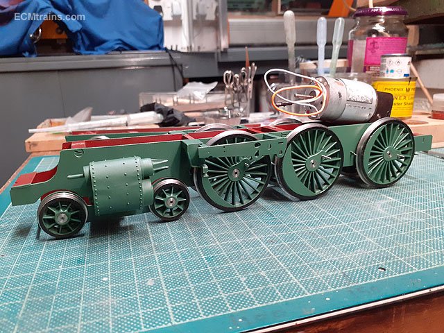
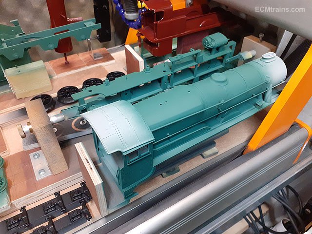
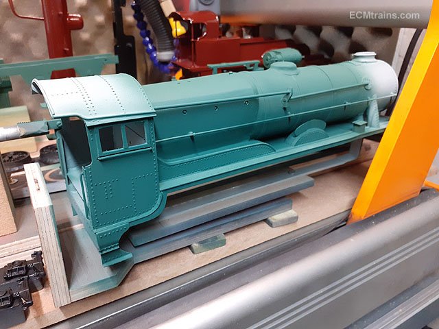
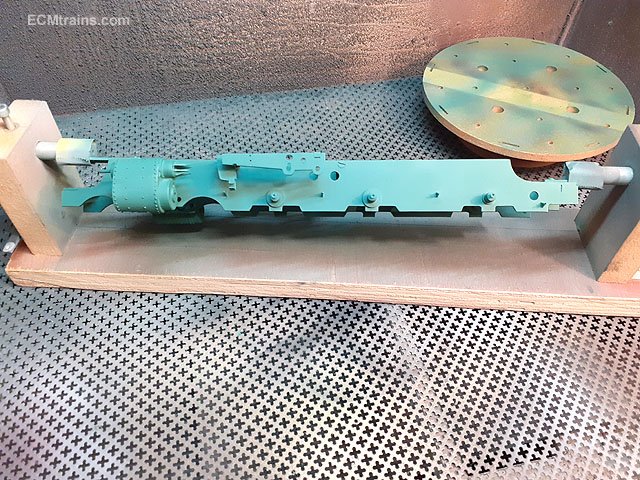
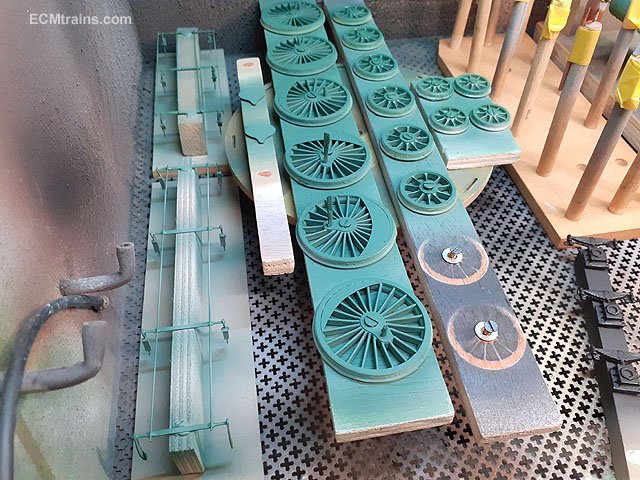
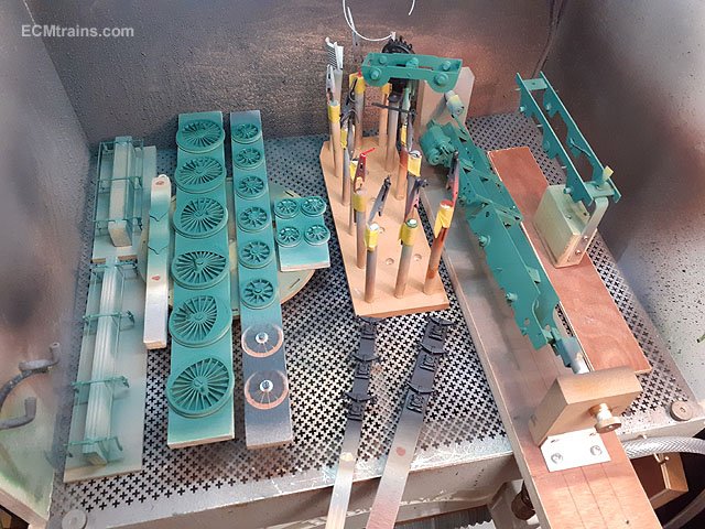
While waiting for that green bodywork to go off I got back to finishing the wheels and chassis. I made up a little jig for painting the wheel tyres satin black, two bits of mdf with M3 threaded inserts to bolt the wheels down loosely on a raised surface. Then rotated by finger while paint brush is applied from the other side. Chassis and wheels are now complete and given 2 coats of Alclad Klear Kote Semi-Matte. The insides of chassis frames were hand painted with red oxide. Chassis up and rolling, a bit premature put the best place to store the wheels and chassis to stop them getting scuffed sitting around! The GSR 800 green was never my favourite livery but it's now growing on me. Eoin
-
My mates Pat & Steve have launched a new youtube channel which will be featuring some of The Fountainhead's not previously released experimental recordings from the early 80's ;- Eoin
-
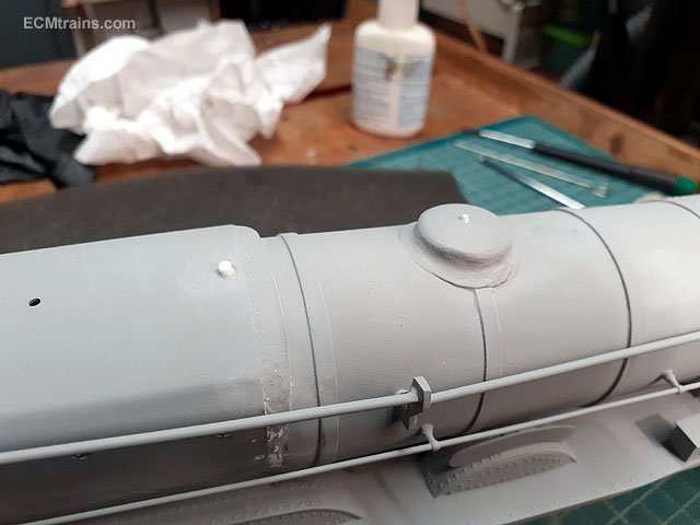
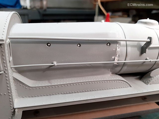
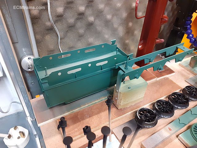
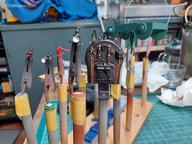
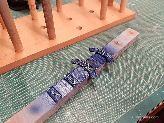
Loco and tender bodies caught up paint-wise with the chassis parts today, after I added a few details to the loco- firebox top detail, steam dome detail and firebox washout bolts, all done with styrene and stuck on with Deluxe glue n glaze which I find the best glue to stick to paint Then touch up undercoat and two coats of GSR 800 green. Detail parts getting their final paint touch-ups, two small gauges will be turned from brass bar to mount on top of the backhead. And first coat of blue on the name and number plates. The name plates are going to be a bit fiddly as they are aluminium and will have to be highlight painted to give a brass look, whereas the number plates are brass and will be rubbed down on emery paper. I should have cut out new nameplates in brass!..... Next step is the black paint to the loco and tender bodies. Eoin
-
In my discussions with chaps that worked on the Castle Layout they sadly reported that 'dubious transactions' abounded in the later days of the layout's life........ Eoin
-
Launch should be on the go in about an hour;- Eoin
-
Airbrushing - paint cup size
murrayec replied to NIR 450 ‘Castle’ Class's question in Questions & Answers
Yes, the compressor with a tank will come up to pressure in a minute or so, if no tank when switched on your ready to go. Adjust the output air to the airbrush down to around 2-3 psi or as required for type of airbrush and paint mix- you need to be activating the trigger on the airbrush when doing this as you will see mainly on a tank-less compressor there is a drop on the indicator so you set the pressure activating the airbrush. Mix your paint to the consistency of milk in a separate container and then decant to the airbrush cup, some paints are already mixed by the manufacture ready to go. Use kitchen towel to clean things but as it gets old and raggedy it starts to shed and those little bits will block the airbrush- change the towel frequently during a paint session. Play with the brush before yo go spraying a model, use sheets of paper to spray on and play with settings and paint mix. Clean the brush regular during use and when finished a session clean it out thoroughly with whatever thinners your using to paint with. Cellulose thinners is a good cleaner if stubborn paint will not move but do not leave rubber O rings or fibre washers in it for to long. Always clean the brush after use and refer to the instructions for details on taking it apart. ....and one on here might tell you to clean it with a sonic cleaner!! Do not do this if you value your airbrush- the needles on these can be forged parts which sonic cleaning will destroy, and anything screwed together can be rattled free and cause damage.... Regardless of type of paint do ware a mask (rated for gas) eye protection, and work in a well ventilated area. Eoin -
Hi JB These guys do foam sheet for packing;- https://www.efoam.ie/foamsheets.php Eoin
-
I'm getting a 'de je vous' feeling looking at those photos! Lovely stuff Eoin
-
The first bits of colour going onto Maedb, this is the first coat of GSR 800 green, it looks a little dark as this is the first coat over the grey primer- chassis, wheels, break gear, and satin black going onto the detail bits. Loco & tender body filling is now complete and are a coat of undercoat behind...... Eoin