murrayec
-
Posts
2,727 -
Joined
-
Last visited
-
Days Won
70
Content Type
Profiles
Forums
Events
Gallery
Blogs
Store
Community Map
Everything posted by murrayec
-
https://www.google.com/search?q=old+irish+phone+box&client=firefox-b-d&sxsrf=ACYBGNQFpWAHswsU6kKUdzpRGDgbHFo32A:1572732743564&tbm=isch&source=iu&ictx=1&fir=OhuA1BrEu4IaiM%3A%2Cvl67x6fI0vBxoM%2C_&vet=1&usg=AI4_-kT3EJwXiQ9UO2BA1_C8QNzRCMPNig&sa=X&ved=2ahUKEwisz4aExszlAhWDr3EKHf9FBWwQ9QEwAHoECAcQHA#imgrc=OhuA1BrEu4IaiM:
-
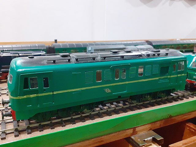
A bit of cream n green and it will be grand! Eoin
-
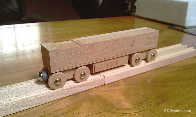
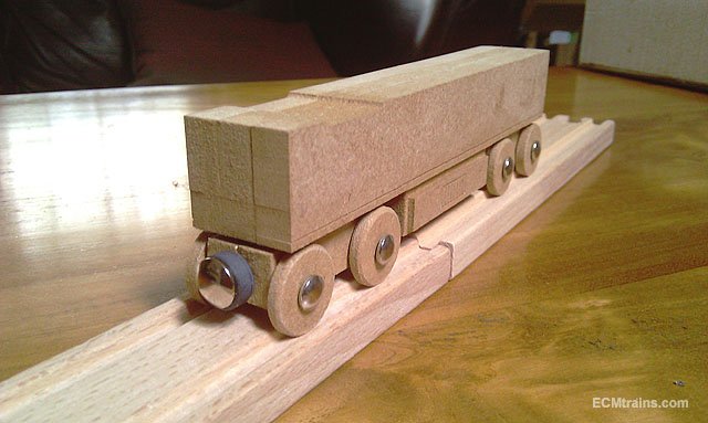
Hi Guys Yes Broithe is correct time is a major problem, but more of a concern is my DARTs are a fine detailed model and would not be suitable for child play and are expensive! On the other hand- I am developing a timber toy DART, one that runs on a timber track available in toy shops and Lidl (which is in their stores now), this DART would be more suitable for child play, but the problem again is time. This is where I am at, rolling chassis and currently working out the body curves and pantograph;- Eoin

- 2 replies
-
- 10
-

-
until
-
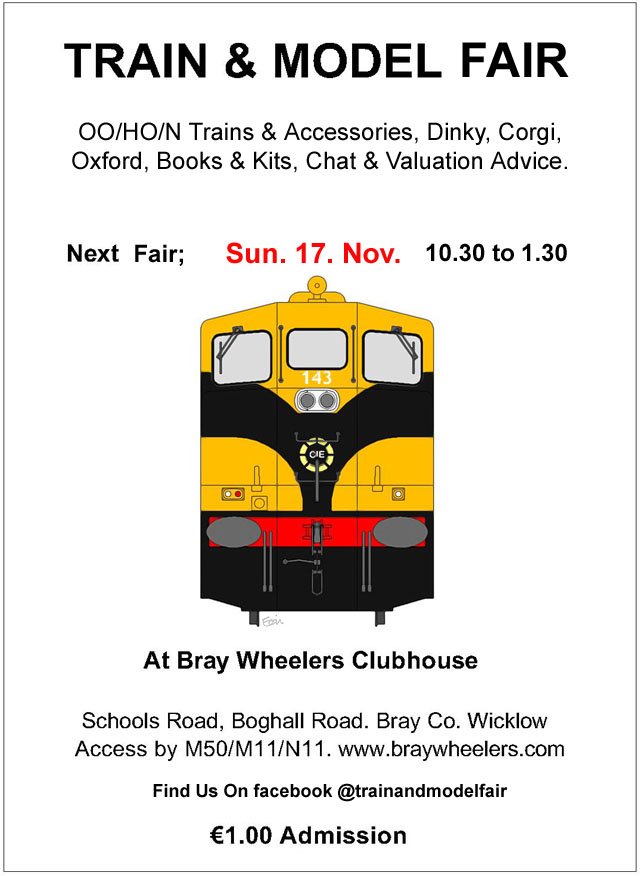
The date for the next Fair;-
-
@Broithe Now that's a big circuit breaker! Eoin
-
I made an aluminium side casing for a BSA motorbike restoration a long time ago, we made it from Coke & 7up cans cast into a home made oil sand mould in a metal bucket, using a styrene-foam master which burned out as the metal was poured in, it worked but boy did we need a lot of cans! the casing has lasted for a long time.... Eoin
-
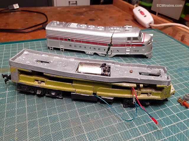
Here is something we generally only see on those old Hornby clockwork loco wheels 'Zink Pest' This is the first time I've seen it on a more modern die cast model, a Bachmann Hong Kong made American thingy.... The chassis expanded to the point that the plastic body had no choice but to split and give more room for the expanding chassis. https://en.wikipedia.org/wiki/Zinc_pest Eoin
-
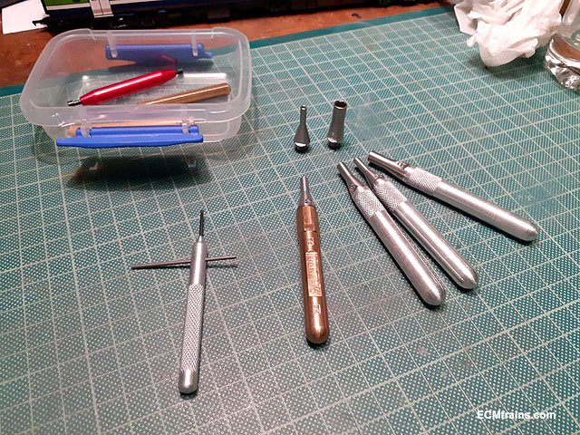
and more tools;- Roxey Mouldings do a nice set of nut spinners 16BA to 8BA with a nicely machined brass handle, I made the other aluminium handles. The heads do need to be screwed on tightly or use thread lock as when unscrewing a nut or bolt the head has a tendency to unscrew itself! nail varnish would work also- I see David doesn't like pink so how about blue with metal flake! The Expo Tools spinners are a pain- the socket is to deep and those little 16 & 14 BA nuts get lost in there- do get the Expo BA spanners though. The tool to the left is an allen key for Slater wheels, a tuned up stick of aluminium with a cut off key forced in the end and Loctited, with the cross bar one can get the right torque and the screw taper locks- the problem with the 'L' allen is it twists n bends and most people give in before the taper locks! Eoin
-
Hi Guys Use a broach to widen out a hole, if one is careful and work it from both sides the hole will stay on centre, a reamer is for setting a specific size hole and is designed to cut a very small amount of metal after one has drilled a hole very close to the required size- if you force a reamer it will break or damage one cutting edge which will give an incorrect size when used later! Eoin
-
Excellent Ken Sure their would have been sparks flying around that anyway! Eoin
-

South Dublin Model Railway Exhibition 2019 list of exhibitors
murrayec replied to DartStation's topic in What's On?
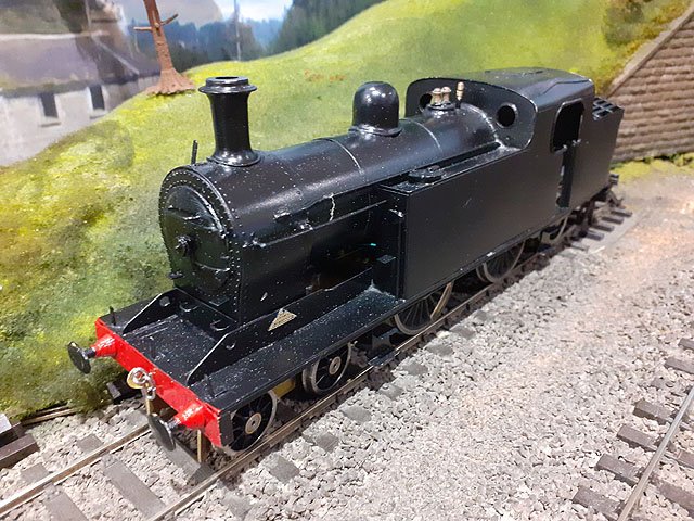
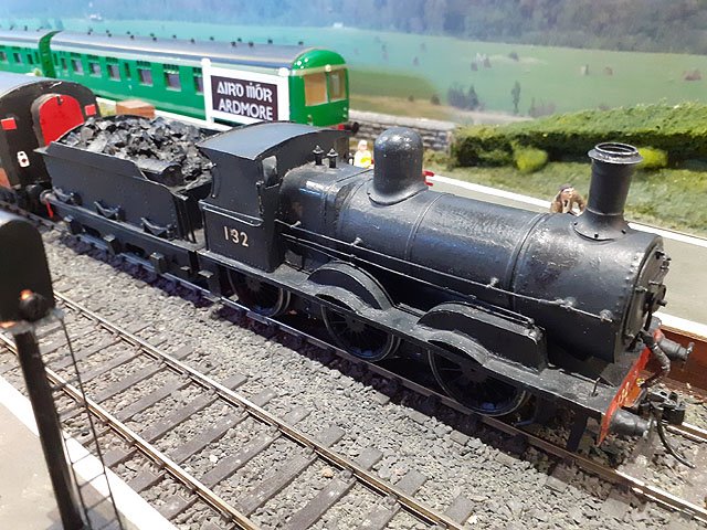
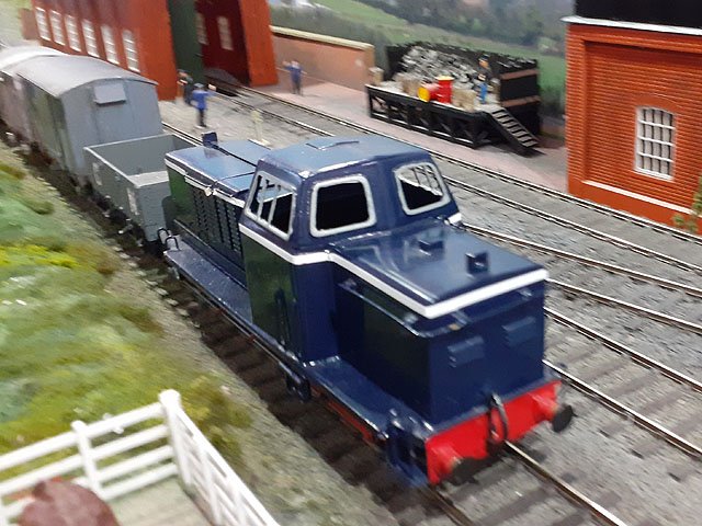
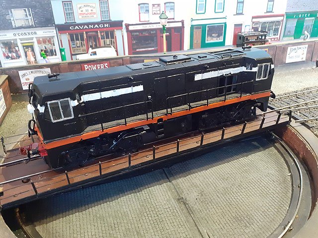
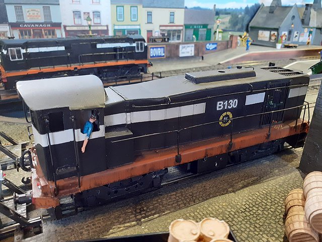
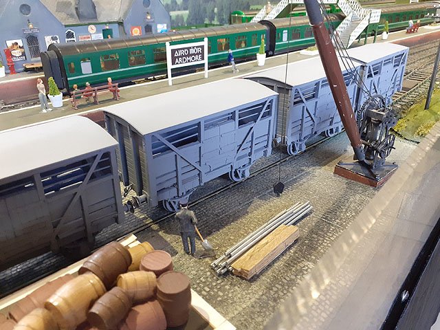
Well that was a very enjoyable 3 day show, I have to say a big thanks to all the chaps that made it possible with their hard work and organisation- well done. And thanks to all who came over to the DARTs and said hello, brilliant to meet and chat with everyone. Every day on the way to food and stuff I passed Ardmore, by the MRSI chaps, I'd snap a look and then run off! Today I got to spend some time there chatting with Brendan, George & Harry and took a few photos of their amazing creations;- Lovely stuff... Also well done to all the layout exhibitors who made the show and the traders who brought goodies to buy- I have a few cattle wagons to build and books to read. Cant wait for the next one Eoin
-
@Broithe can we make suggestions?...... Choose your date by their track laying skills, choose your date for their ability to render and install a realistic back-scene, or their calm control of the knobs in a rear shunting situation!..... What do you think, what do you think? can I have a job|? Eoin
-
I have one of the 'coupling couples' for the back seat of a DART! though the mecha is large and have not worked out how to get it in yet. Eoin
-
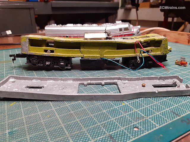
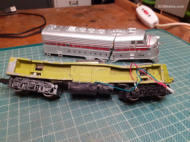
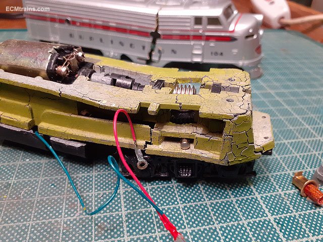
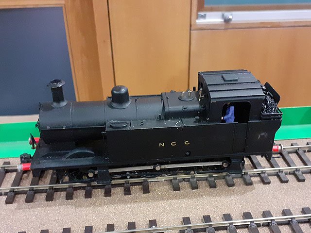
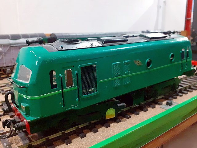
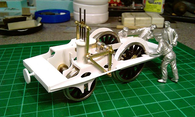
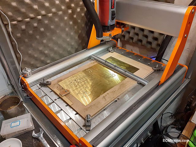
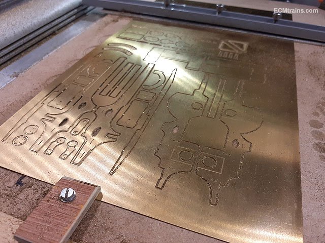
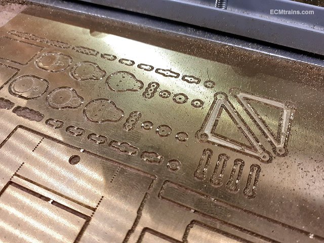
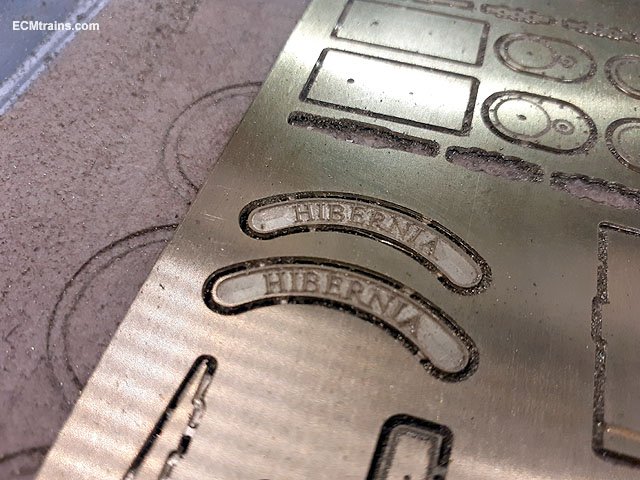
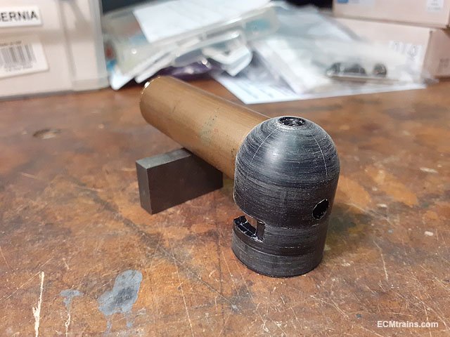
I have been hacking away on the Hibernia Loco build which featured way back in my 'murrayec projects' in the Workbench area, I have decided to carry on showing the build here. If you want some background info on the project here is a link;- So after building the test plastic-card chassis I made a few adjustments to the drawings and then sat on the project due to the workload back then. A couple of months ago I started back at it and set up drawings to mill the parts from .5mm & .25mm brass sheet to build a brass test chassis and other components which will be needed to test fit out and to use to make moulds for white metal castings. I have also set-up a brass tube boiler and machined up a firebox former from 30mm dia nylon bar, again when the fitting is done on the firebox the former will be used for moulding the final unit. The boiler will be worked out when the motor and gearbox are installed. That's the fire hole in the back, the lower section is the ash-pan and the side cut will hopefully allow the chassis by! Last week the milling started on the chassis parts, cylinder base & heads, valve gear, bellcranks, and the nameplates in the .5mm brass;- This chassis has inside and outside frames, with the slot & tab frame stretcher construction I reckon .5mm will be plenty strong? Bellcranks are half depth milled to give the cast iron look, and in the footplate stretcher one can see the .5mm dia chain drilled holes to be opened up into slots for construction- the chassis frame tabs will stick up through these. Again half milled nameplates- can't wait to see these painted and the brass text all shined up. Next will be .25mm brass splashers, footplates, smokebox, smokebox doors, and more chassis fittings......... Eoin
-
Hi There will be an overhead Gauge O track! in the new museum with 4 'non-Fry-made' trains running, but unfortunately not including the 121 loco. Eoin
-
Hi All KMCE's 'Wicklow South' will be paying a visit to the Fair this Sunday, a great opportunity to see the amazing diorama, locos and rolling stock- not to be missed..... Eoin
-
lighting for hornby 0-6-0 08 diesel shunter
murrayec replied to controller's question in Questions & Answers
Hi controller That chip only has 2 switch-able functions! the green wire & the purple. F2 not staying on sounds like your controller is set for momentary switch like a toot on your horn! need to refer to the manual to switch that off, or remap what you want to switch to F3. If those red lights are directional loco rear? they should be switched by the directional wires- directional light wires are white for front & yellow for rear. One has to wire up so that the white & red lights alternate depending on direction. Then you have 2 function switches to play with- use one of these for cab light, and for maximum coolness wire up the cabs for the two functions and then only the front cab light can be switched- in each direction. Eoin oops! an 08 only has one cab- even better a free function switch!! -
Hi Leslie I'm down for 4 but I'll take a Five Pack..... Eoin
-
Hi All, Just a reminder of the Train & Model Fair is on this coming Sunday. Eoin
-
David As PP says above 'Brilliant to see Fintonagh in motion', the locos in motion, the depth of the buildings and back scene are just stunning. Eoin
-
Excellent Ken, that looks great I cant help noticing the perspective of the photo under the bridge- do you use Photoshop, if so do you know the 'distort' transformation with the four handles at each corner- tug on those and you can change the perspective to be more in line with the laid track and platform. Pulling the top left corner would be a start, would be a trial n error exercise but I reckon it is worth doing! Eoin
-
Hi Guys Evergreen do 2.5mm (the largest) Quarter Round ref; 250, which would be ideal for the corners of the tank, if one was to stick a horizontal styrene strip to the inside top edge of the sides one would not notice the internal square sides of the Quarter Round. Eoin
-
Re; Water Tank Structure. On reflection! no discerning Railway Man would spend his good money on my first submission so this morning I revised my guess to a more economical solution, this is the kind of way plastic tanks are built today and am sure it came from the past;- Curved corners to the outer sheets would add significant structural capabilities and could lead to even more cost savings for the Railway Man- like the photos of the green tank above! Eoin
-
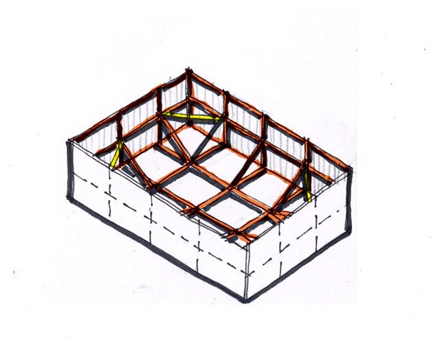
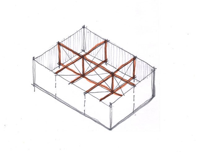
Tony 1 sqm of water weighs 1 tone approx, which puts some pressure on the sides especially at the top, so I reckon it might have bracing on the inside- angle iron verticals and horizontals with angle iron diagonals in this kind of fashion at a guess;- Note the diagonals go from inside bottom to outside top! Eoin