murrayec
-
Posts
2,747 -
Joined
-
Last visited
-
Days Won
70
Content Type
Profiles
Forums
Events
Gallery
Blogs
Community Map
Everything posted by murrayec
-
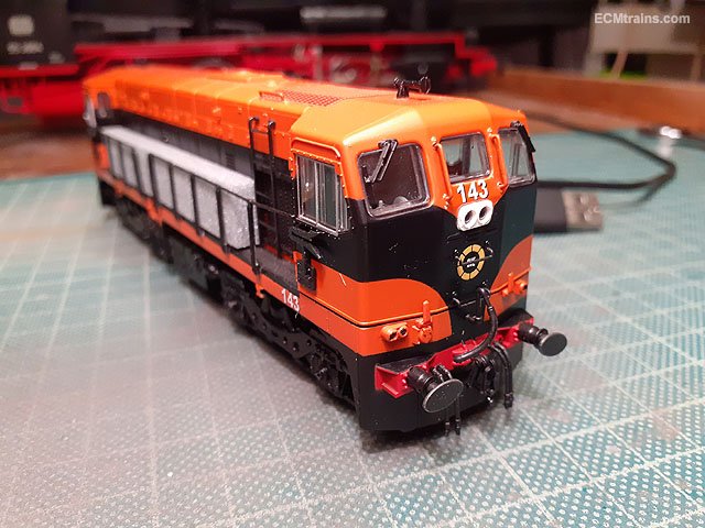
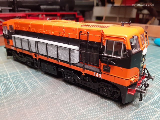
Hi jhb As NIRCLASS80 says above use a stick, or preferably a bud and add a small bit of T-Cut to soften the numbers, it leaves the paint nicely polished for applying the new numbers. Des in Studio Scale Models can supply decals for this, I'd recommend replacing all the numbers just to keep the font the same- nothing worse than having the new '5' not match the existing font! Here's one that I did earlier! converted to 143 to pull the 'Transition DART' with des's decals;- Eoin

-
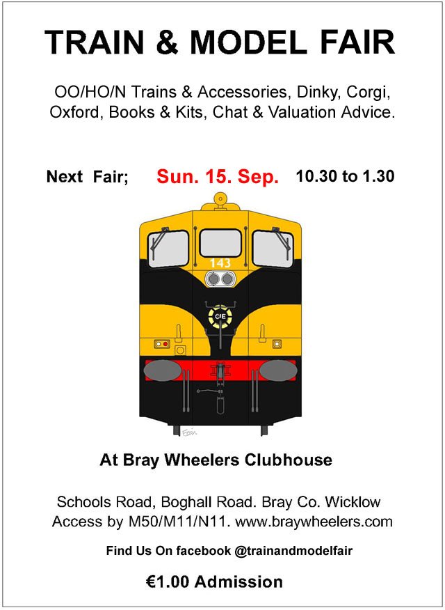
oops! reminder is a bit late but...... Don't forget the Fair is on tomorrow!
-
Hi Colin R Drawings for no. 10 are featured in 'The County Donegal Railway Companion' by Roger Crombleholme, ISBN 1-85780-205-5, including some detailed photos. Also the 7mm Narrow Gauge Association's drawing book no. 6 has drawings for no. 10, ISBN 0 9513300 0 4. Unfortunately nothing on no. 9 Eoin
-
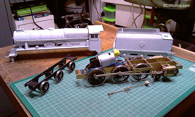
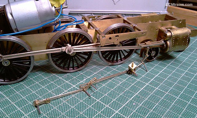
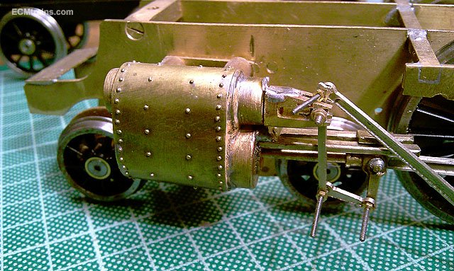
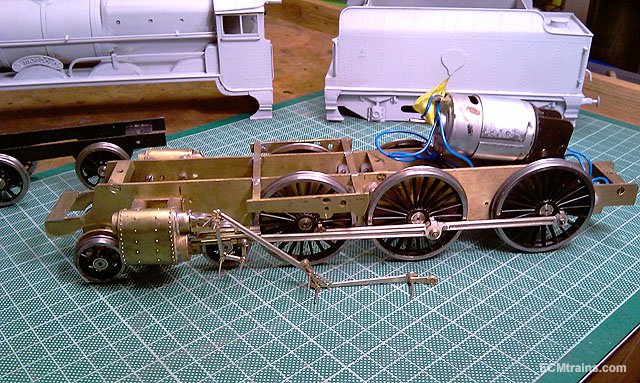
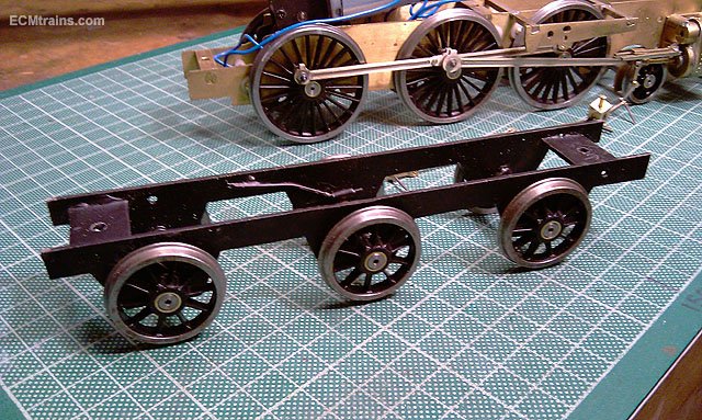
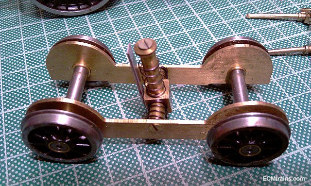
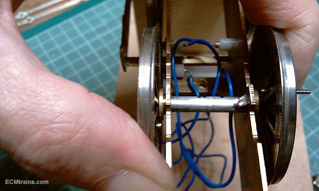
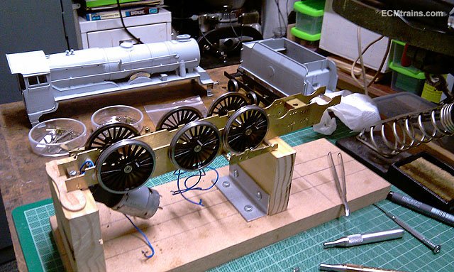
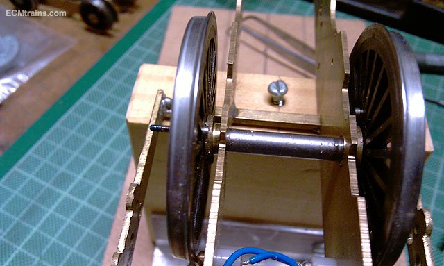
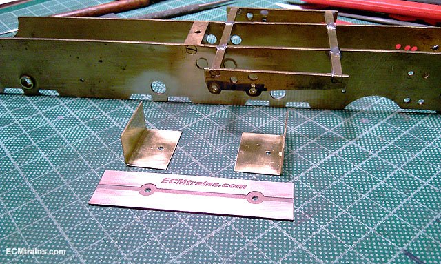
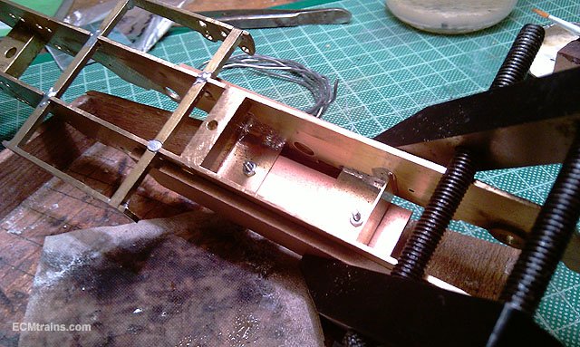
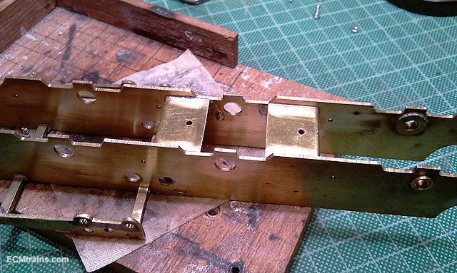
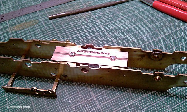
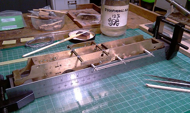
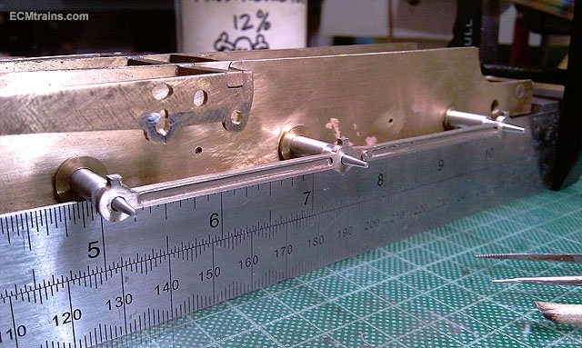
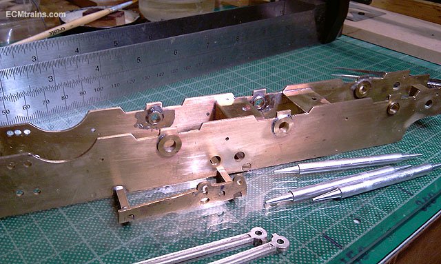
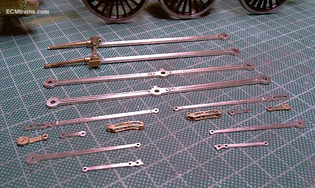
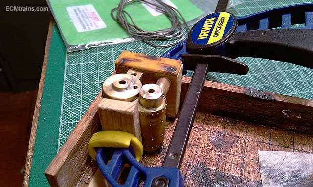
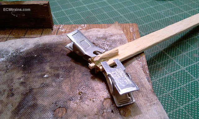
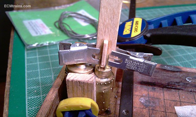
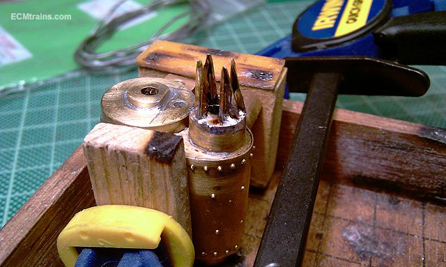
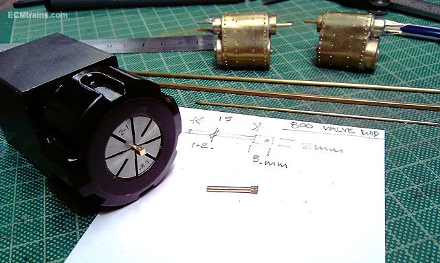
Another Class 800, this time it's 'Meadb' is in the workshop for completion- valve gear, break gear, wheel weights, some cab detail, painting & lining. As it came;- So I set about stripping down the chassis and came across a number of issues;- only two of the axle bearings were soldered into the chassis, the others had been super-glued in but all have come free to rotate with the axles- see photo of bogie above, their all loose to. The plunger type electrical pick-up system was very poor, some of the plungers were frozen in their housings and did not make contact all of the time. The chassis required a few more frame spacers- it was a bit bendy! So with a plan of action the frame spacers were made up from .5mm brass sheet in the 'L' shape for stiffness, a pcb copper clad pick-up board was cnc'd out- as I'm going with wiper pick-ups off this board- no stinking plungers! Holes drilled, M2 nuts soldered to the new spacers and the plate fixed with M2 bolts- this holds the frame spacers in when soldering them in the chassis. Spacers in, time to solder the axle bearings in. The coupling rods were cleaned up, to be used with the axle jigs to centre the bearings when soldering them in. I do this on a glass sheet with two rulers on edge to support the chassis by the axle jigs. Done. The cylinders were cleaned up after removing the old crosshead guide bars, the valve front end was drilled to take the valve rod housing that sticks out the front- done with 1mm dia brass wire locctite'd in. The valve back-end guides were cnc'd from .5mm brass sheet and folded up for soldering on. I came up with a lolly pop stick trick to hold these parts in position for soldering- a cross shape with a spigot that seats into the valve end and the parts clipped on? Worked a treat! The remainder of the valve gear was cleaned up and I noticed we're missing some parts- the Valve Rods and the Anchor Links! The link will be cnc cut from NS sheet with other parts later, but the valve rod requires a bit of machining- 2mm square bar was rounded up on the lathe with a file leaving a 3mm long square at the end, then cross drilled for a rivet, then .5mm slotted to create a clevis, after a bit of filing. I made these a bit fat as the holes in the valve housing are large. Wheels have been cleaned up and the wheel weights in .5mm brass being epoxied on. Eoin
-
The tender weighs a tonne also, I suppose making up for such a small loco so that it can pull something- my Gauge O Hibernia model is about the same size physical and it was a little loco. Yes the splashes would be a problem but I'd be more worried of being knocked back by those driver levers- they would swing back and forward alternatively which were used by the driver to adjust the valve timing. Eoin
-
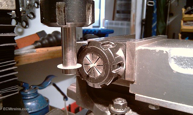
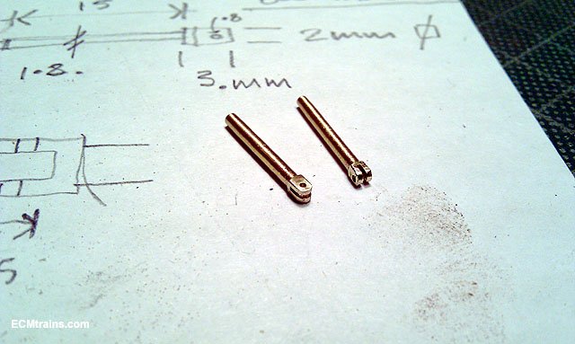
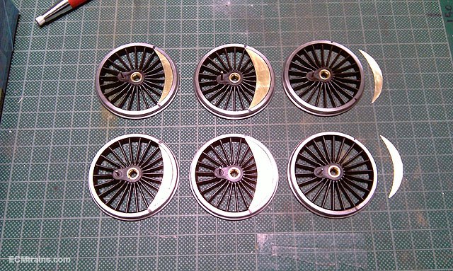
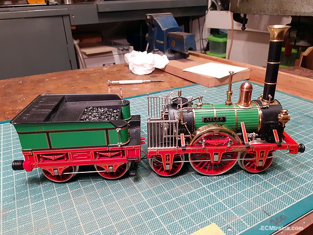
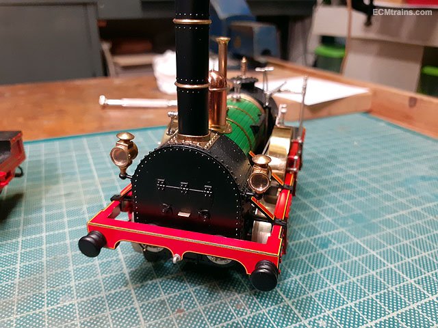
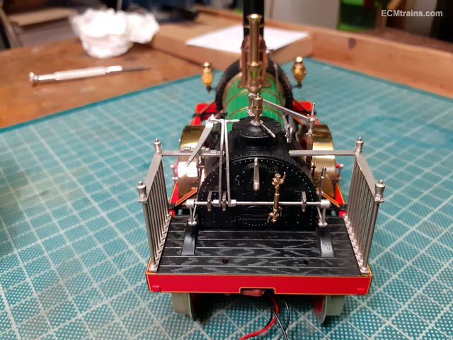
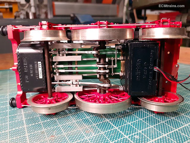
Here are a few photos of a Gauge 1 Adler loco in the workshop for some minor repairs, it's my next favourite loco after the Hibernia, and maybe a few others from the Dublin & Kingstown Railway era! It's a lovely model by Marklin and has some beautiful detailing- and working valve gear. Eoin.
- 9 replies
-
- 7
-

-

-
- adler
- adler marklin
- (and 1 more)
-
A tiller can sometimes be refereed to as 'The Wheel' so I think it could also be an 0-1-0! Eoin
-
Good man George My fave is the one over the stone bridge Great to see Eoin
-
Hi PP Here is one on CIE buses;- http://stenlake.co.uk/book_publishing/?page_id=131&ref=1060§ion=RdTransport I also saw a book by the same publisher with CIE trucks and vans but cannot locate it on their website, Des McGlynn had a copy of it at the Stillorgan Toy Fair..... Eoin
-
Looking great Ken
-
until
-
The September date for the Train & Model Fair;-
-
Don't forget the Train & Toy Fair is on this coming Sunday.
-
PP At the last Train & Model Fair one of the chaps said it 'was like luggage'.... Eoin
-
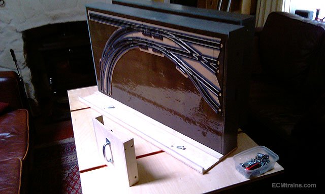
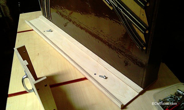
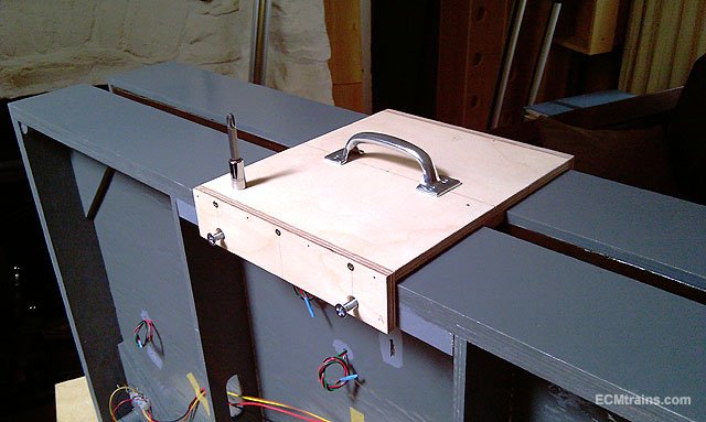
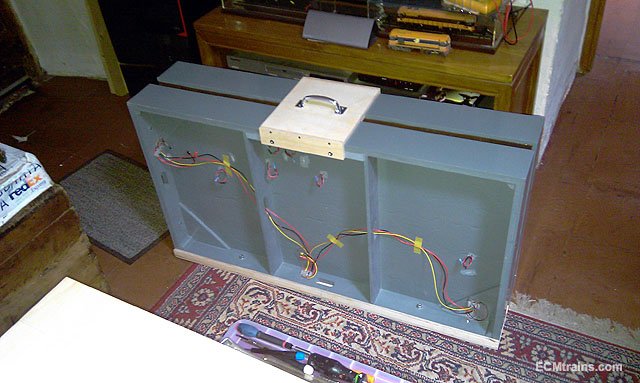
The baseboards transit system, here are a few photos of what I have settled on for the moment- 2 no. base trays and 2 no. lifting handle plates;- 9mm birch ply base tray to take two of the baseboards, with M8 T-Nuts set in at the centres of the baseboard dowel system- so that two boards bolt to this tray through the dowel holes. The base tray and lifting handle plate have a 9x20mm ply spacing strip down the middle and 9x20mm edge strips (9x40mm on the handle plate) to hold the boards snug n tight when all is bolted up. With the second board bolted onto the base tray the lifting handle plate is installed and secured in place with M6 counter sunk screws into threaded inserts in the baseboard frame. Two of the boards ready to go....... Eoin
-
@patrick Try Des in Studio Scale Models, I think I have seen him issue them in the past! Eoin
-
Sorry Leslie It's one of your SL&NCR's, I was able to squeeze in some top-hat wheel bearings also. I'll take 4 kits Eoin
-
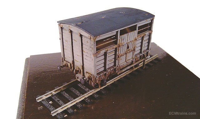
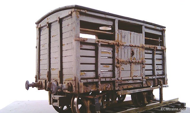
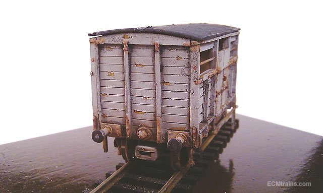
Hi Leslie I'll be picking up a few at Blackrock also, I've been working out some weathering details in anticipation- here are a few shots of the cattle wagon left in a siding gone to hell! Just about finished except for a straw bedding flowing out the sides mixed in with a bit of dodo!! Eoin
- 114 replies
-
- 11
-
-
-
JasonB I would love to have a space like that, dying to see how you fill it up....... Great work on gutters and flashings- you have added years to its life. Eoin
-
Hi gph2000 As far as I know Silver Fox gives you all the parts for the model body and chassis, but Worsley gives you the body and chassis etches and no castings- not that it needs much castings to complete it, i'd go for the brass kit, but it is a more complex build needing a few self made parts and more figuring out.... that's the fun bit! Eoin
-
Don't run it any-more until you have a good look inside! at a guess I'd say one of the gears is stripped and that's what's what making the grinding noise- most likely the worm gear in one of the bogies is riding over the wheel gear under and is stripping it's teeth?? Eoin
-
Hi @David Holman I got it on the Scale Model Shop website;- https://www.scalemodelshop.co.uk/?s=nutter But looks like it's out of stock at the moment! Have a look at their other tools though- very handy stuff on here.... Eoin Hi @Mike 84C That's the problem with rivets- drives one to drink Eoin
-
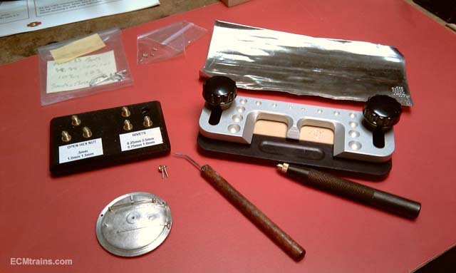
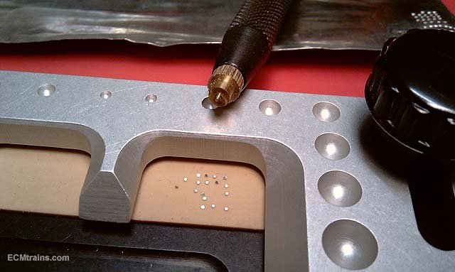
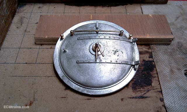
Nuts & rivets can also be done with the 'Nutter' a very handy tool for pressing out nuts & rivets in lead sheet for sticking on to your model;- and the above rivets added to door straps The tool comes with tools of your scale choice and different scale tools are supplied separately. Eoin Eoin
-
PP You could use Postpal if he refuses to send to you- with the American address Postpal you have to register for 'home delivery' which costs a bit more but one does get the parts! Eoin
-
PP Here is a very helpful web site for the lathe with many links to articles on mods and parts- it may help;- http://www.cartertools.com/ Eoin