KMCE
-
Posts
540 -
Joined
-
Last visited
-
Days Won
29
Content Type
Profiles
Forums
Events
Gallery
Blogs
Store
Community Map
Everything posted by KMCE
-
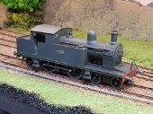
423 Practical Completion. Many thanks for the comments guys - they are much appreciated. Finally reached the end of the construction phase on 423 - it has taken just over 2 months from cutting of frames to this point. Latest work included fitting of springs for front axle, draw hook and vacuum hoses. Box section and PB wire were added to simulate sand pipes. Pick ups and wiring for motor are complete and after much fettling we have pick up from all axles. Wheels quartered and coupling rods fitted followed by a test run to fine tune the quartering. Finally we have motion!! Off to the paint shop now........ 20181229_182156.mp4

-
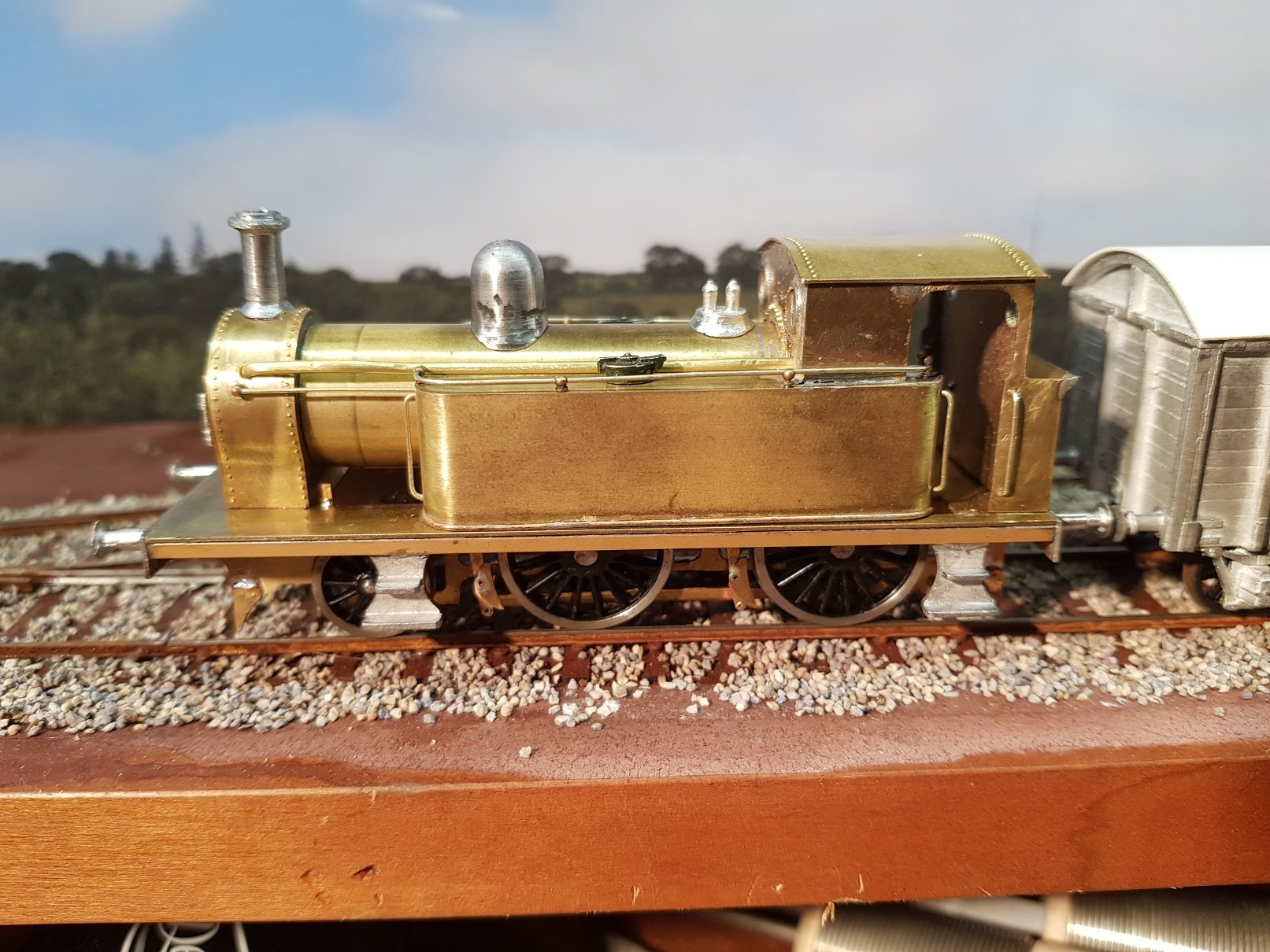
Got back to doing some work on 423. New roof created which fits better than the last one. Quite a lot of detailing done which takes a considerable amount of time but does start to finish off the loco. 423 with an SSM convertible wagon for company! Handrails and knobs were from another partial kit bought some time ago on e-bay, as were the tank fillers, steps, dome and chimney. Handrails knobs on the sides of the tanks are not fixed yet which allows the handrail to be removed if needed for painting and finishing. Chimney was shortened, re-joined and turned on the minidrill to smooth. Safety valves, smokebox door and buffers were supplied by @Mayner, of these parts. Slight incident when heating the handrail on the smokebox door - bit too much heat causing a small hole. I can fill this later when painting rather than trying to do something with it now. Working on the chassis in parallel so pick-ups on drivers only at present; pick-ups needed on leading wheels. Motor in and wiring almost complete. Guard irons fitted front and rear. Coupling rods to be fitted once chassis is motorised - I find it easier to work without having to repeatedly disconnect them for access. Still a lot more to do but it's starting to come together rather nicely. Cheers Ken
-
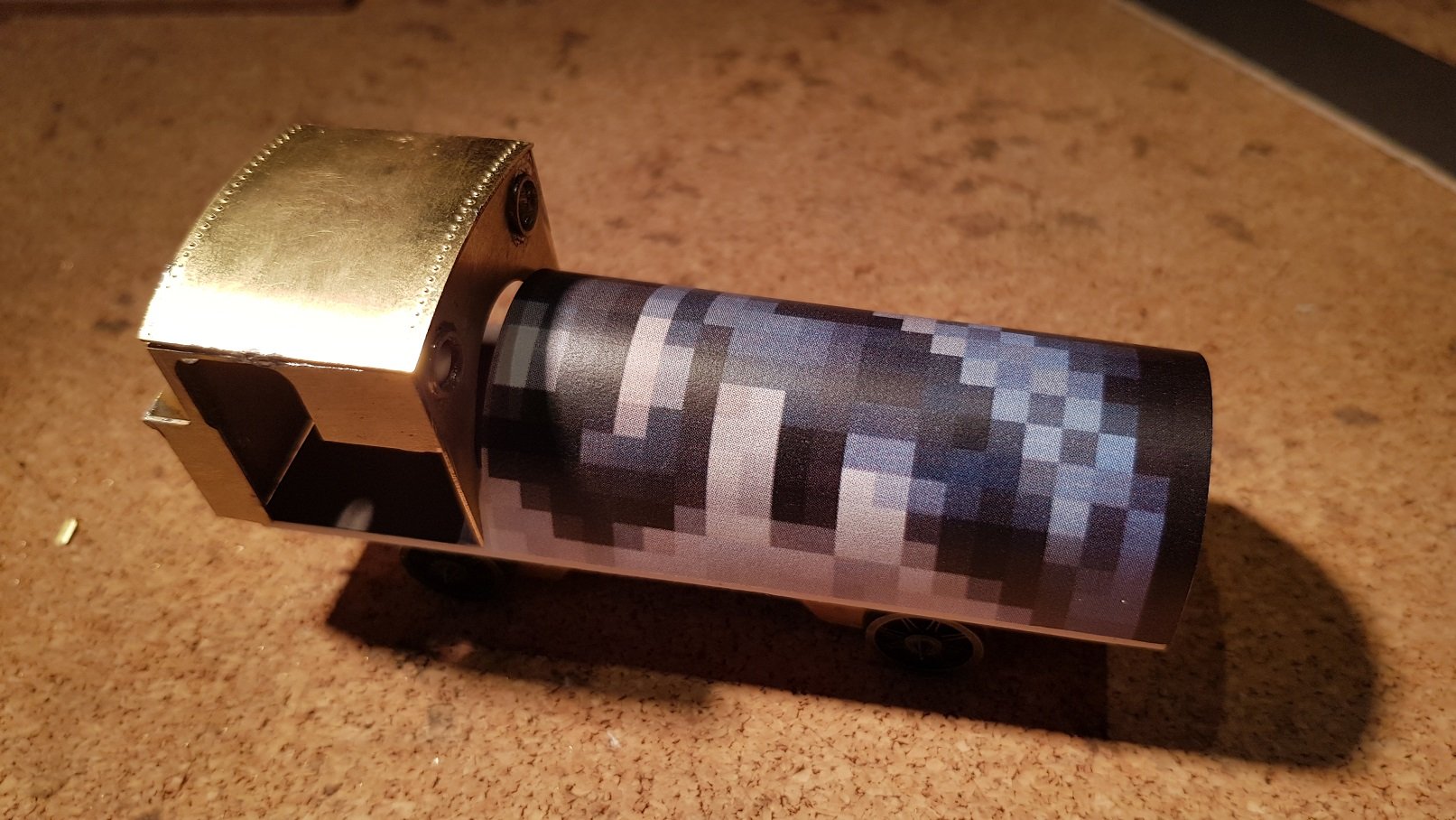
I had a go at this using Shapeways for the Class 495 and as JM noted above, the finish is quite lined as the plastic is laid down in layers. Pre painting stage: Up close these lines are quite visible, however with a coat of primer and at normal viewing distance, they are not overly obvious. Finish is not bad, with cost of €58 for the printing and delivery. Quite an amount of sanding / finishing would be needed to get to a polished finish, however the more detail added, the more difficult it will be to smooth the surface! For the moment, I think I'll stick to brass until printer quality improves. Ken
-
Excellent........Christmas Present arrived early. Looking forward to putting these together!! Many thanks John. Ken
-
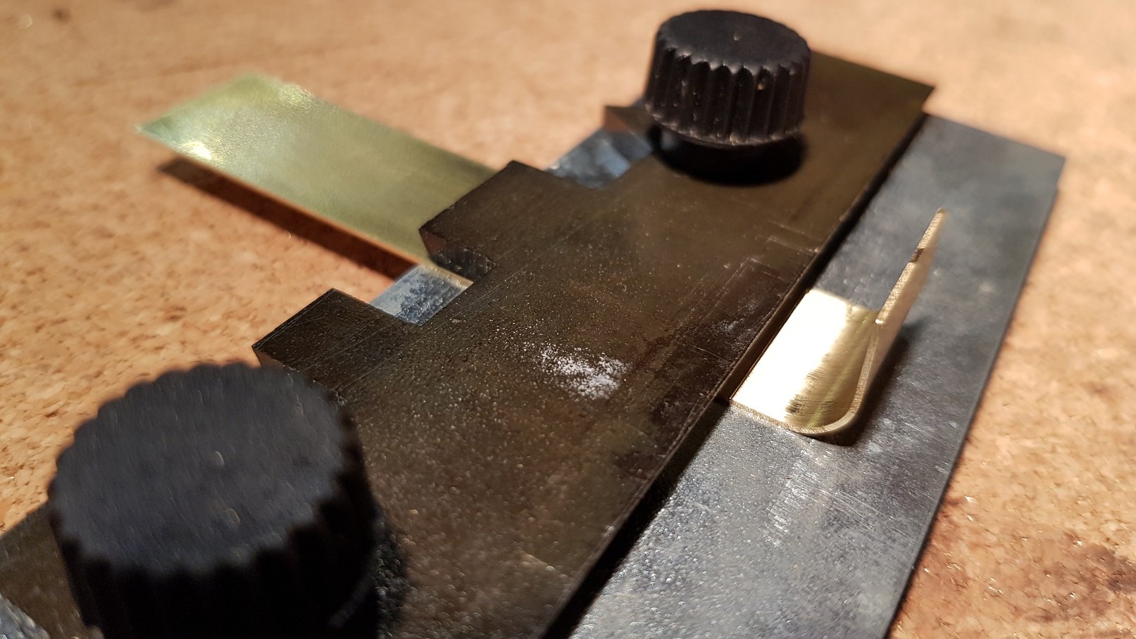
Hello Snapper, As noted by Eoin above, it is a hold & fold tool with the top inverted to act as a backstop to hold a round bar to allow bending. The version I have is the RP Toolz Etch Bending Tool "Hold n Fold" - 18cm long. Cost me £33.50 via e-bay but it is an excellent tool and much needed when working in brass. Hope that helps, Ken
-
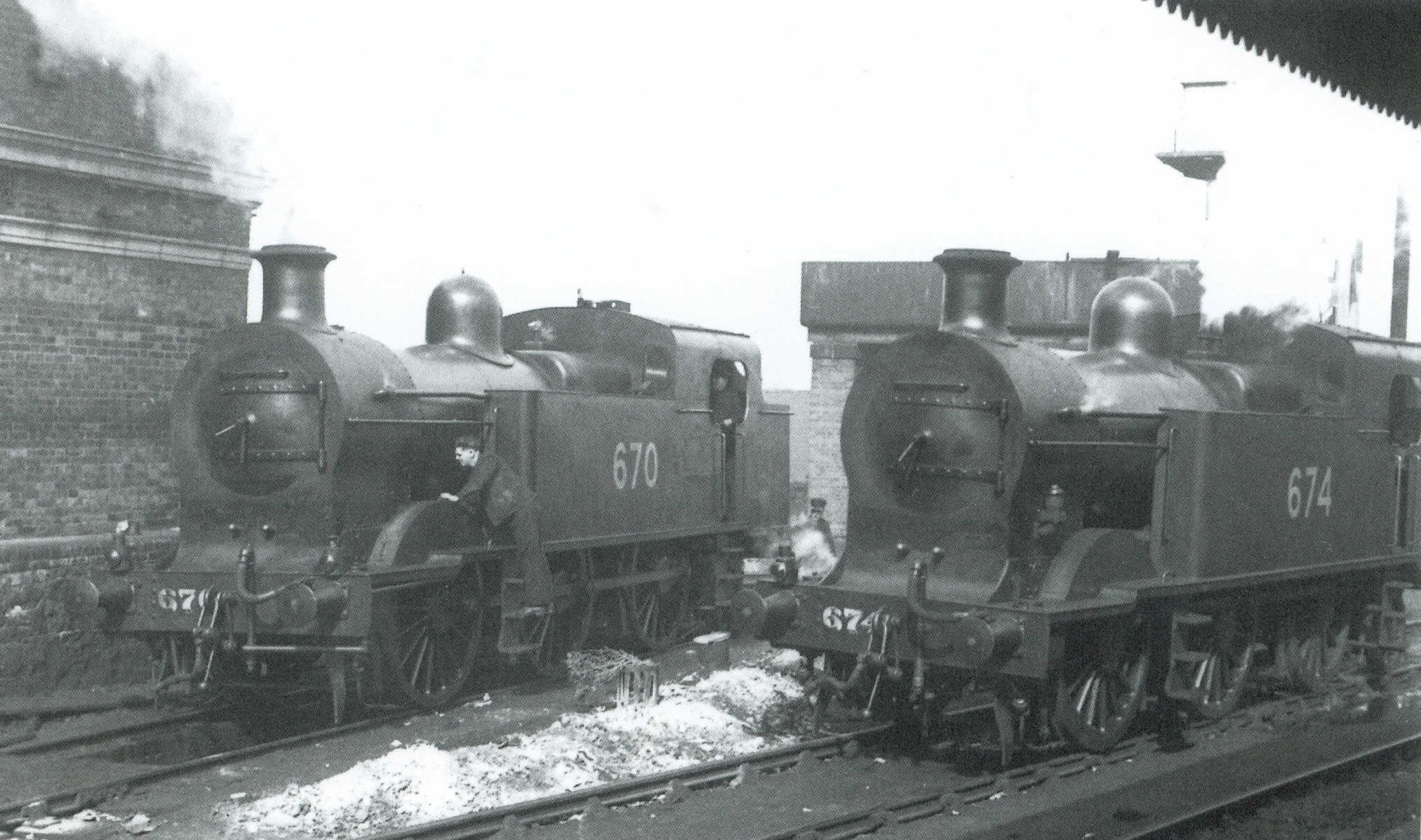
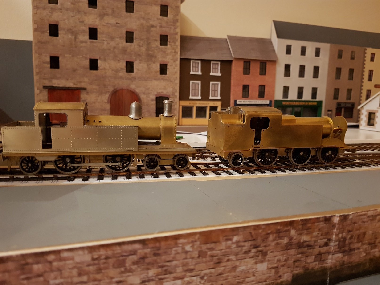
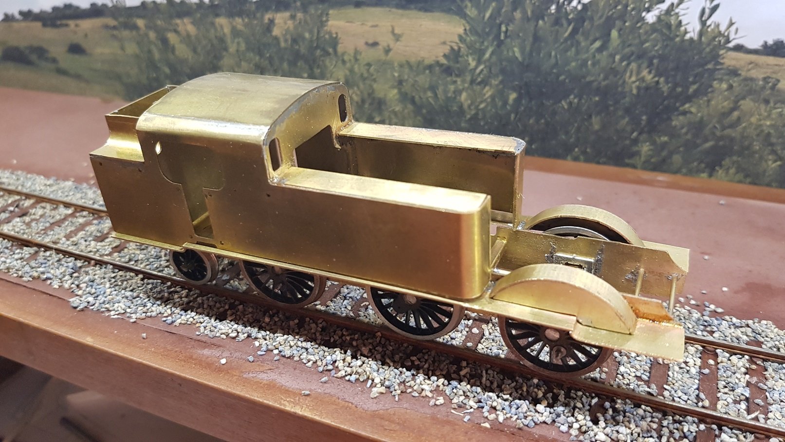
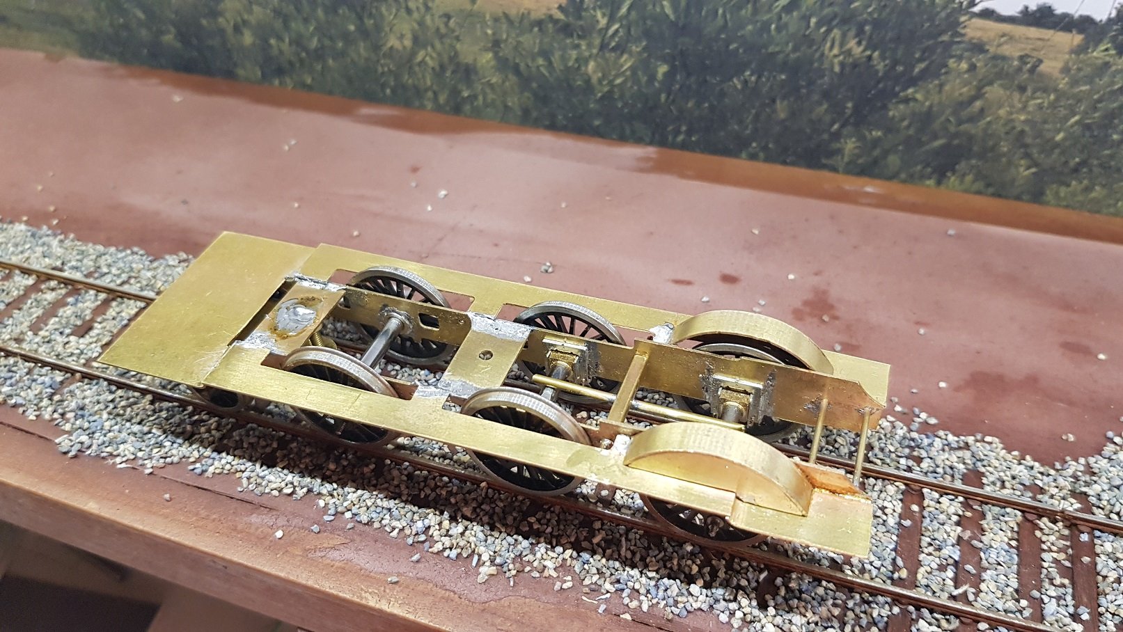
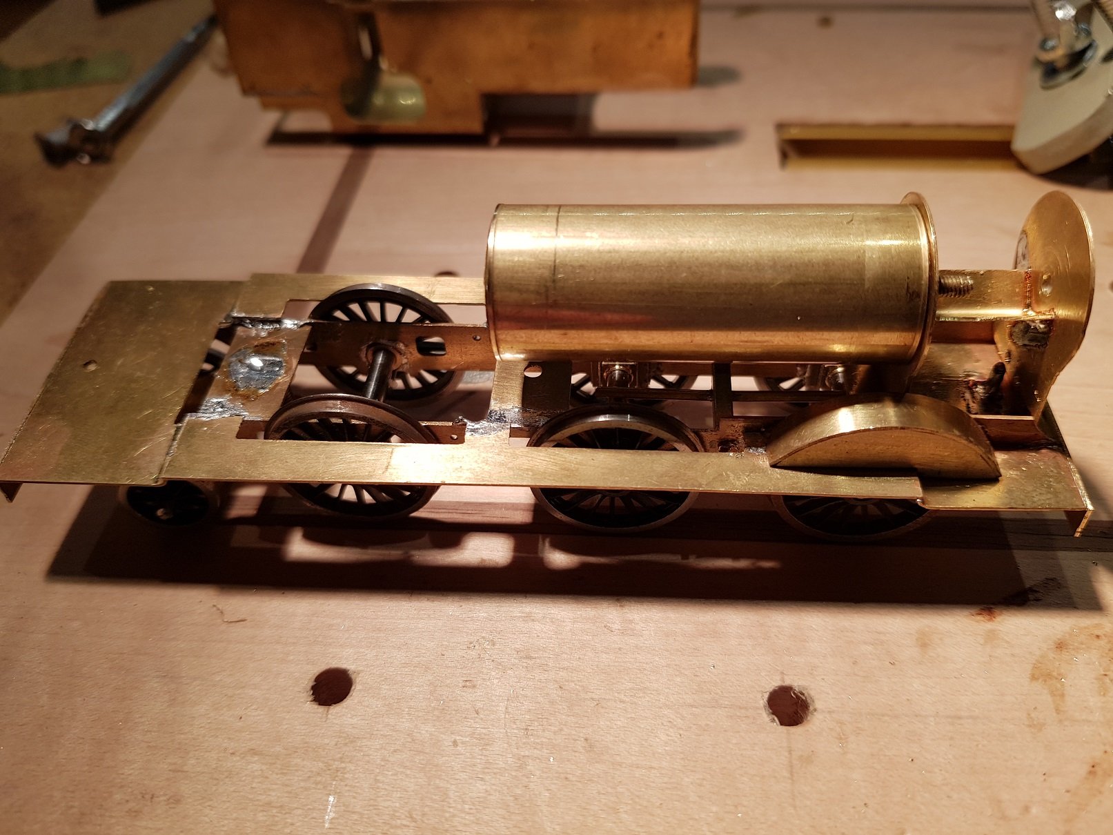
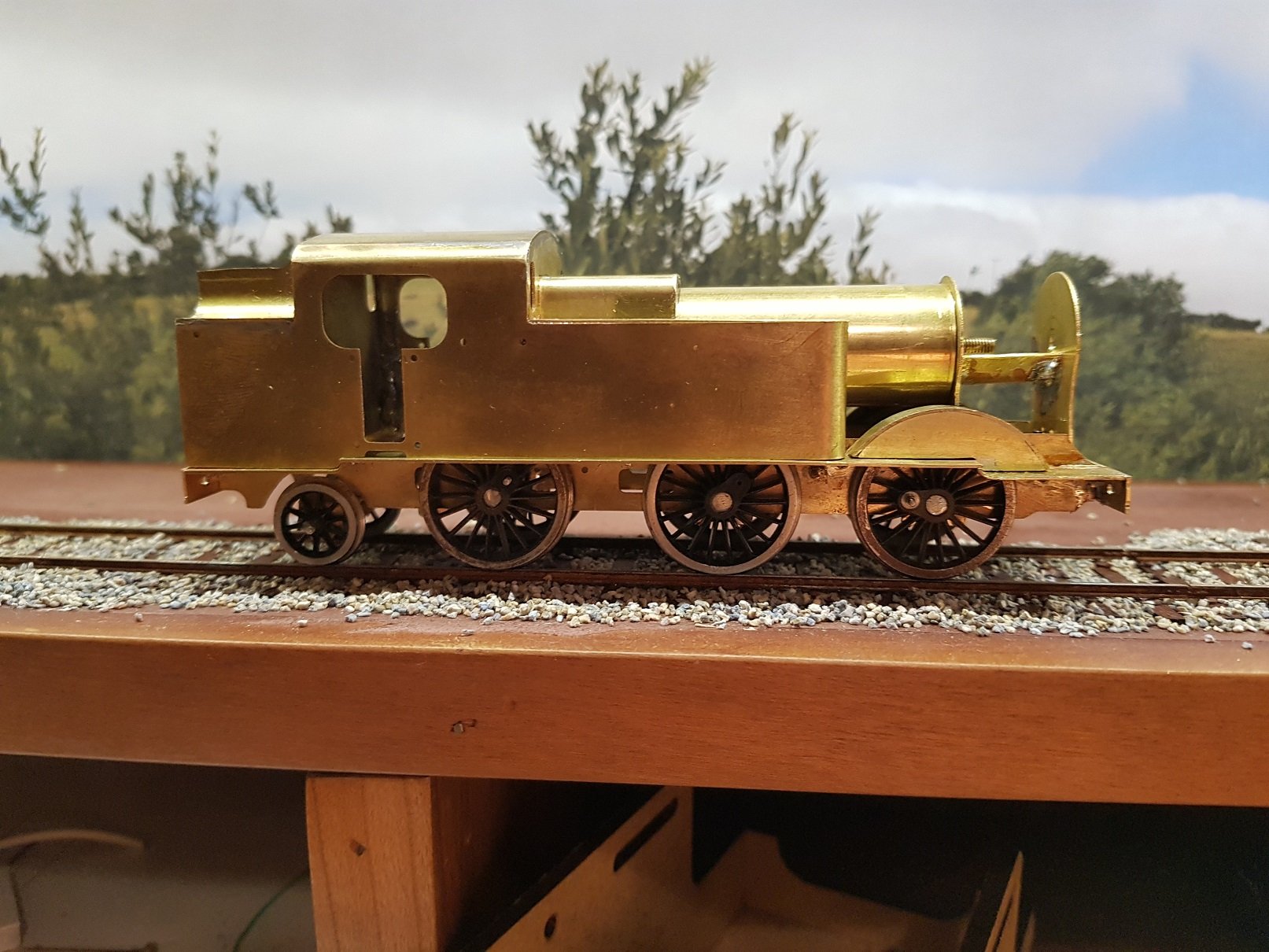
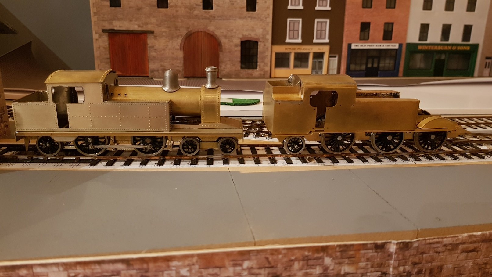
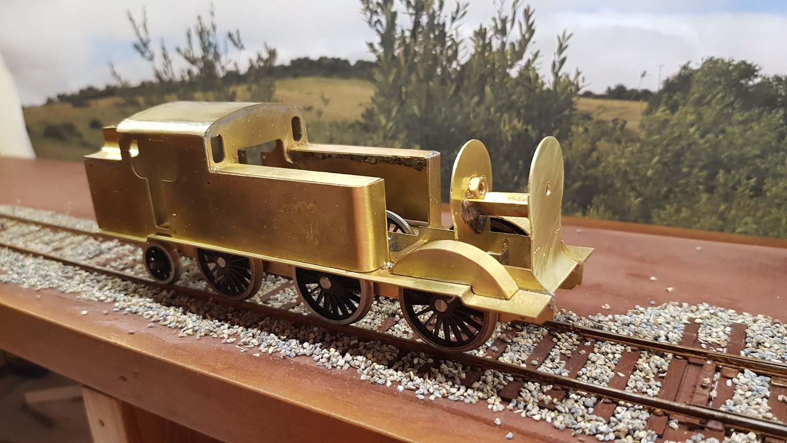
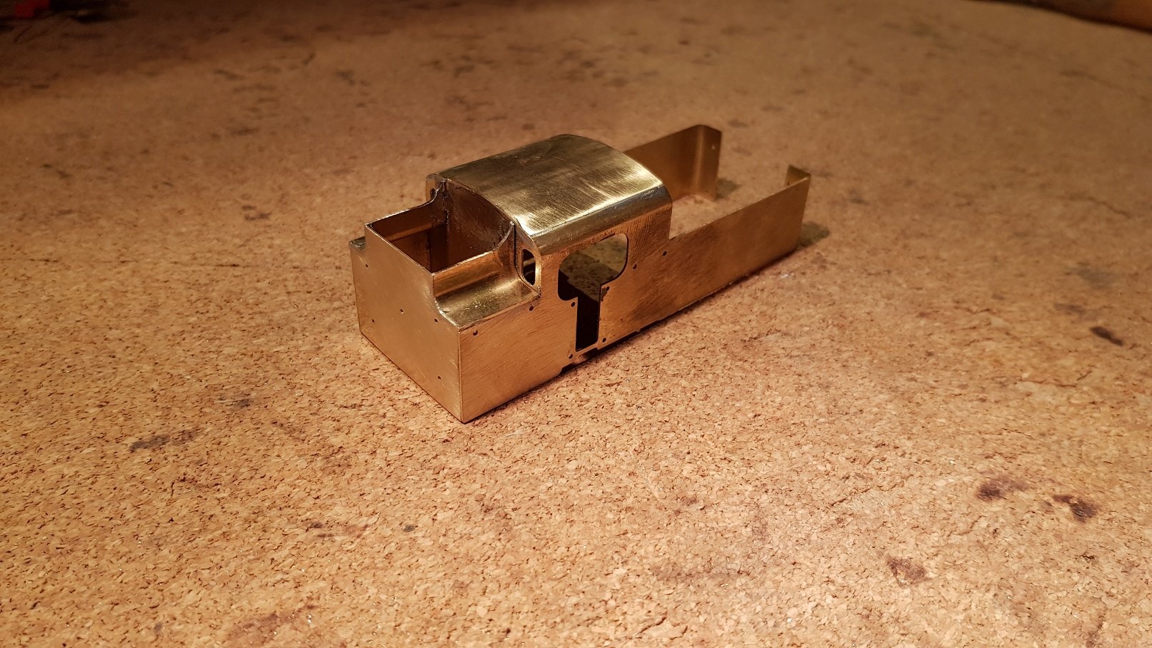
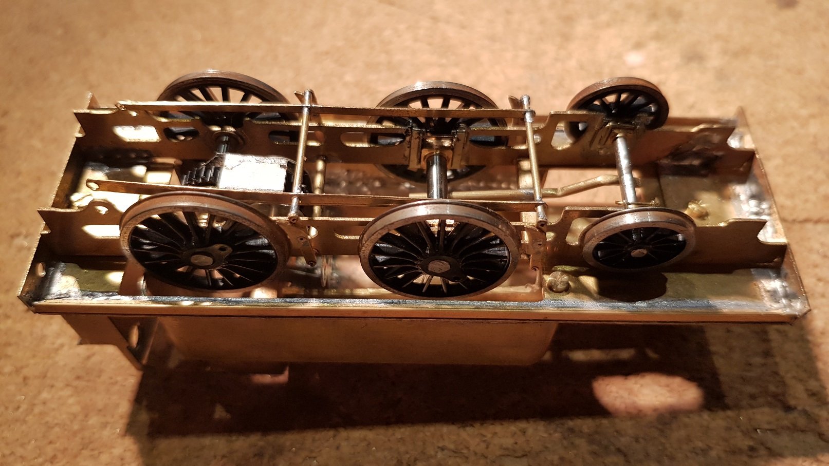
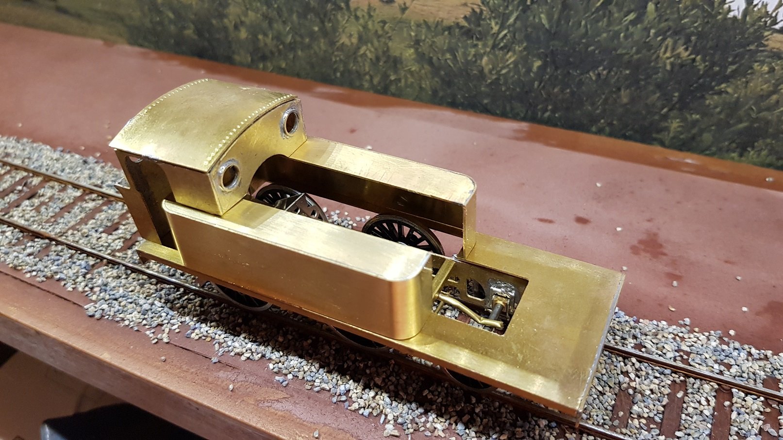
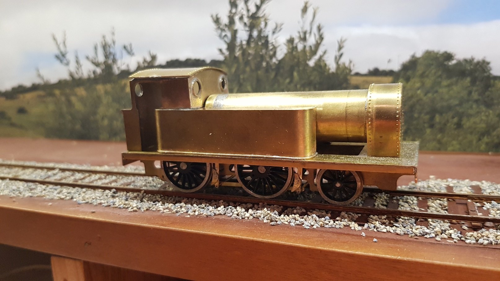
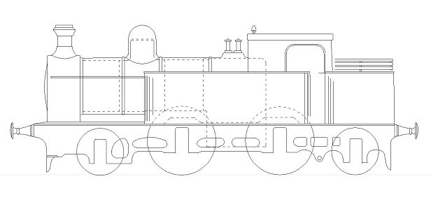
Latest Loco alluded to above, is the GSR 670 Class 0-6-2T These locomotives 670 - 674 were built by the GSR for the ex DSER line to handle commuter traffic between Greystones and Dublin. From all accounts they were complex machines with inclined valves and limited access for maintenance and repairs. Photo courtesy of the "Good Book" (Clements & Mc Mahon) Constructed in 1933 with Z-type boilers and mainly of welded construction resulting in smoother lines. Drawing was developed again from sketches generously provided by IIRS and developed into a cut drawing for the CNC Mill. Parts cut out and construction commenced on the cab area first as this is of great interest due to all the curves. The split level footplate led to a different approach - rather than a single footplate with a hole cut out, profiled tabs were cut which were then fixed to the frames. This allowed both the split levels, but also to retain the distinctive high frames at the smokebox area. Compensated chassis again with fixed rear axle for motor and gearbox, with middle and front axles in high level hornblocks. Compensated beam between font and middle axle. Trailing bogey is carried in a pony truck cut on the mill and bent into shape. Chassis and footplate constructed to get to here: Add the body shown before and we get: What is nice about these locos is the smoke box; large with a curved front plate dropping down between the high frames. Smoke box formers were created, curved, drilled and fixed. Boiler barrel is 18mm pipe with a captive bolt to thread into the smoke box. This brings us to here: Belpaire section of the boiler was formed and soldered to the cab - still need to fix boiler barrel to belpaire section, however that may be a simple tapered slip connection which will facilitate dismantling for painting and maintenance. Put it all together & we get: What is interesting is the relative size of locomotives. Not having actual prototypes available to compare we are left with comparing statistic in books, however, you can read as many books as you like, but when you see locos on the track you start to get an idea. What is noticeable is how big the 670 locos really were - they really fill out all available space on the footplate. Compare 670 class vs the 458 class: More as time permits! Ken
-
Eoin, PM sent re drawings. Ken
-
Eoin, This is looking good - coupling rods look excellent. I'm currently working on one of these in 4mm & have drawings, so could have helped with the research!! Difficult loco to build due to the different levels in footplate, wrap over cab roof, curve in the smokebox front, and very interesting bunker area. Quite a challenge and a very enjoyable build. Some small problems with drawings which need some amendment to fix some issues. The position of the front curve in the footplate is in the wrong position on the drawing which has impacted on the front splashers, pushing them too far forward - should be relative easy enough fix though. What is nice to learn is the relative size of locos. Read as many books as you like, but when you see locos on the track you get the true scale. What is noticeable is how big the 670 locos really were - they really fill out all available space on the footplate. Probably a bit late to offer assistance, however if there is any more info I can provide, please do get in touch. Ken
-
David, I have the Poppy;s loco box for 4mm which is excellent for construction of chassis - it does give plenty of space around the frames for soldering. My understanding of the pin with the coupling rods is that it's a simple rivet - you have to take care not to peen to tightly? For the 0-6-2T I'm working on a the moment, I ended up using a track rivet as the rivet to hold the coupling rods together which worked rather well. NIce looking chassis BTW! Ken
-
George Dent's books are excellent. I bought both volumes on weathering which are superb and provide an in depth look at various weathering methods which I am looking forward to trying. Ken
-
Welcome to the world of brass, where all things are possible!!!!
-
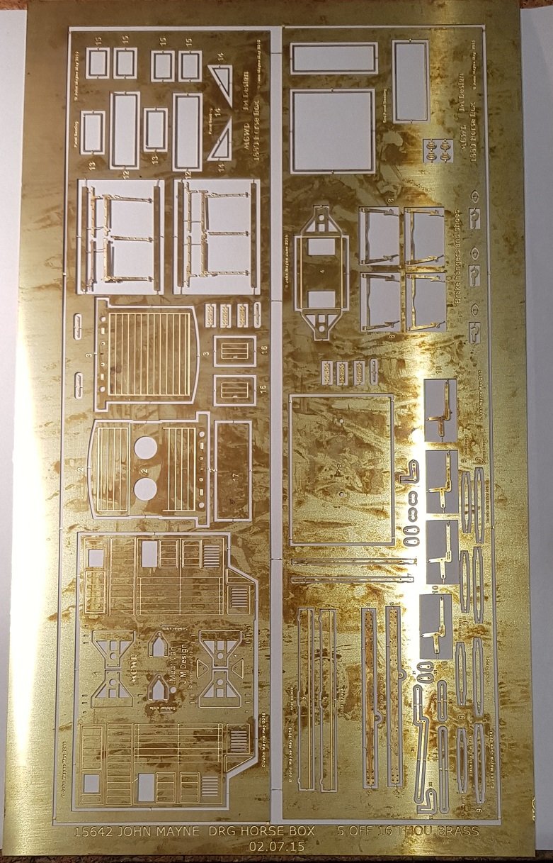
Excellent. They should help finish off some locomotives. I would be interested in taking a horse box and meat van from you if I can. Do you want to send over an invoice for Paypal & I'll organise payment. Ken
-
John, These are fantastic with incredible detail - well done. I gotta get me some of these!! Two quick questions: Are these available immediately (ie to put in with some castings????) Are they suitable for 21mm Ken
-
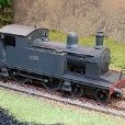
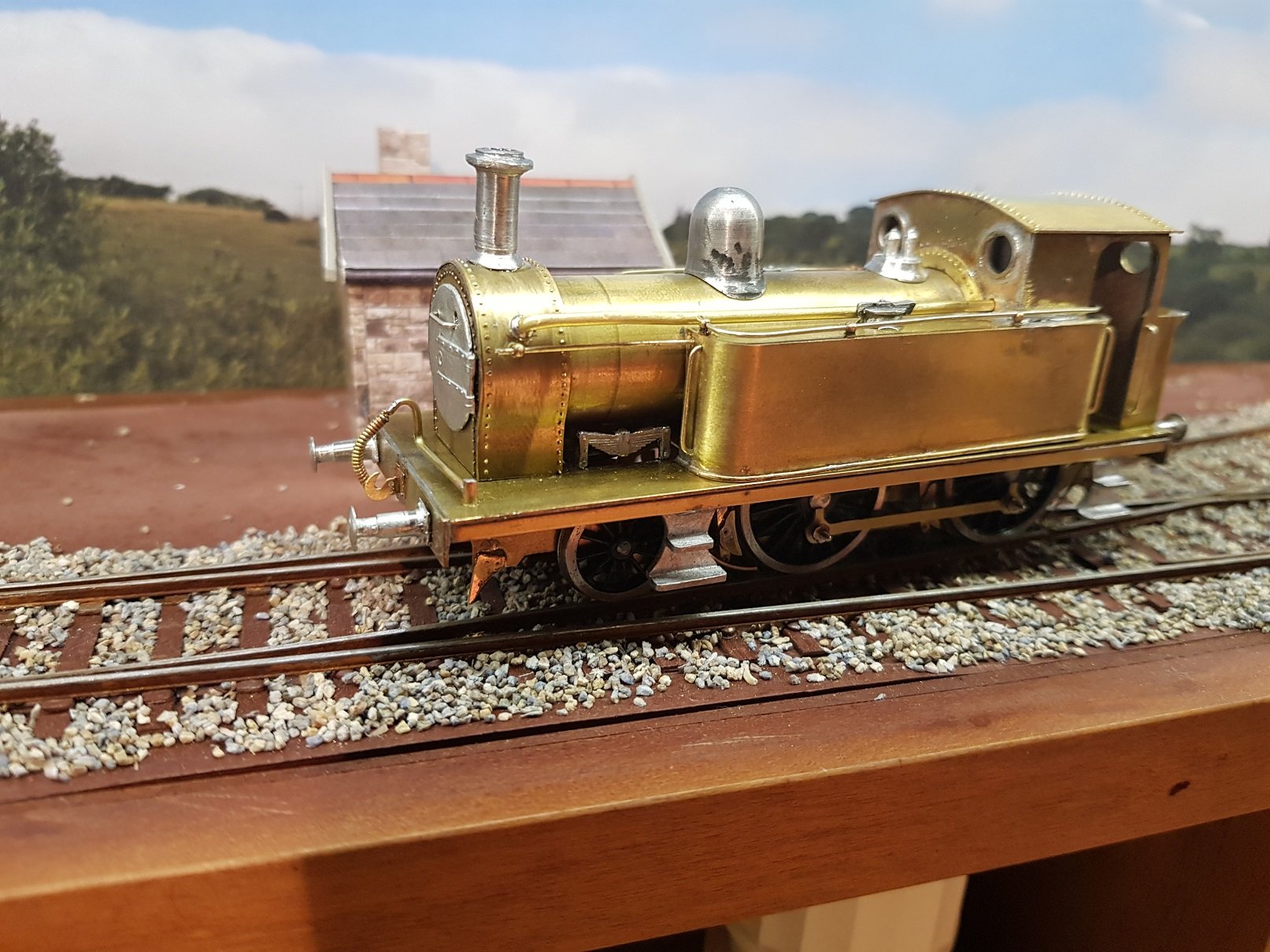
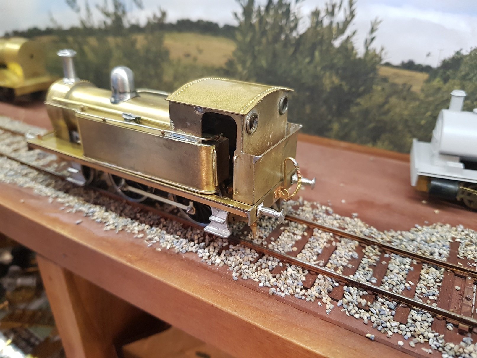
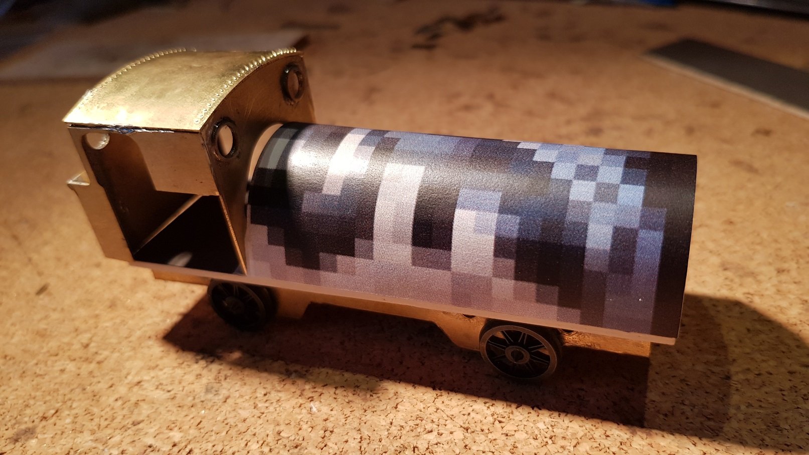
A little teaser for the next loco on the bench. 0-6-2T DSER loco with distinctive rear tanks and bunker. More soon....
-
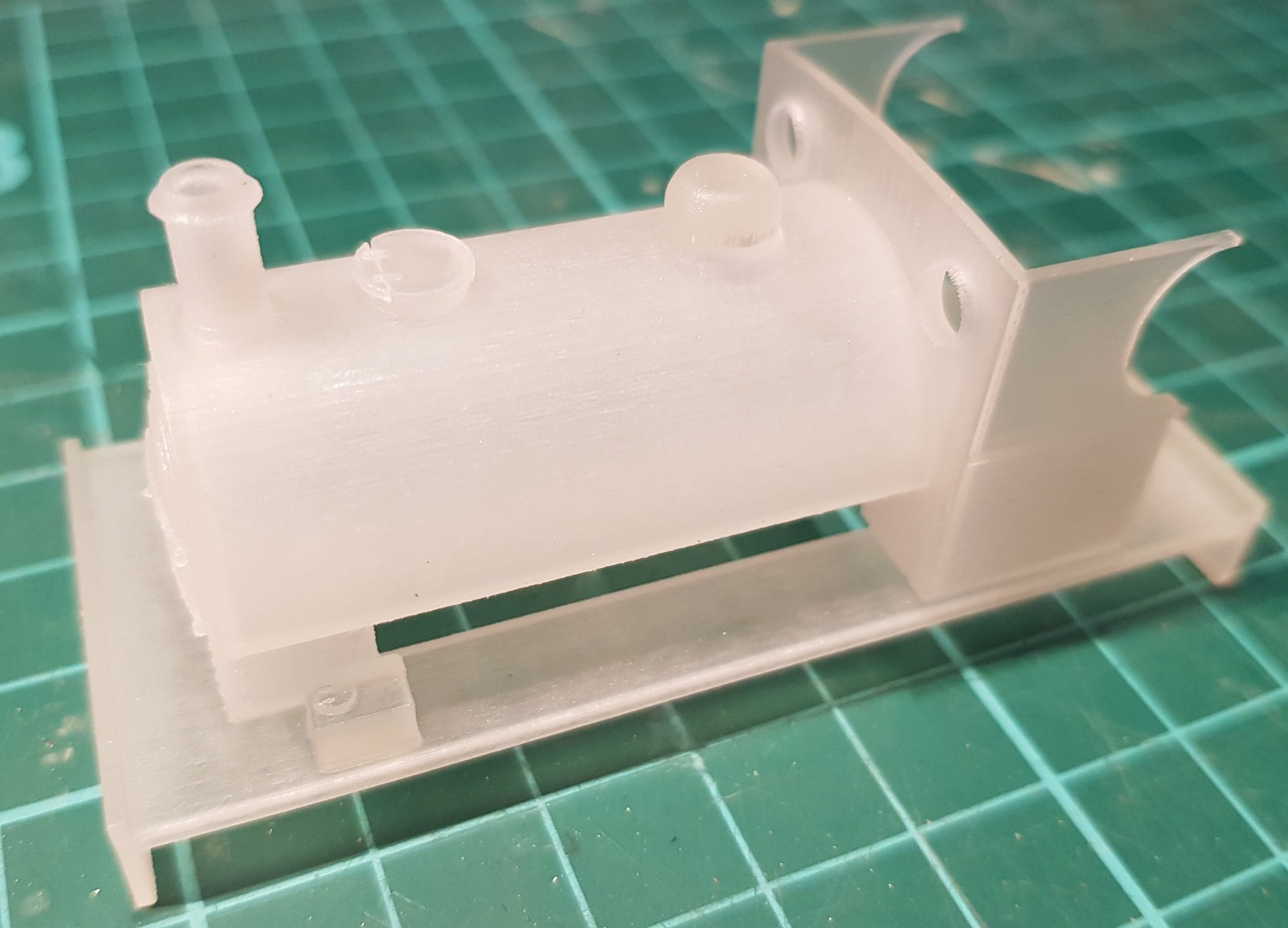
OK - so progress. Quite a bit since i updated this page. Tanks were formed with the curves front and rear. Tops added and excess trimmed off. Given the size of the tanks the cab front was trimmed to meet the top of the tanks rather than cutting into the tanks. Tanks are rather large on this locomotive and fill out fully to the sides of the footplate. A trim detail at the bottom of the tank finishes them nicely to the footplate. The difference in cab width and the tanks is quite pronounced. The boiler and smokebox were then formed and mated up to the body. Some fettling needed to get the tanks and boiler to co-ordinate together. A trim plate over the boiler at the cab front is needed to close the joint - it is quite distinctive. Roof will be need to re-done as it's a fraction too small. Fixing points are located at rear holding the bunker and cab, front holding down the smoke box, and front sides of the tanks. Generally holds things in place and allows access for maintenance.
-
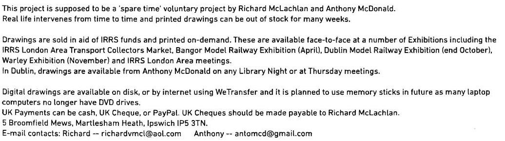
Hello Colin, My contact is Anthony Mc Donald - both his details and Richards are as per the attached image. I elected for the digital download which, for me are a bit more flexible - you can zoom in and out rather than using a magnifier! Hope that helps. Ken
-
I bought the "MGWR Compendium of NPCS & Goods Vehicle Drawings" at the Raheny show. Very nice images and good information. Some of the originals were very faded so some dimensions can be difficult to read but these are the exception rather than the rule. One of the images is of a Passenger, Luggage and Brake Van - Branch line, which I'm drafting up at the moment. It is 30' six wheeler with raised central brake compartment. Hopefully the drawing will provide enough information to build a model. What is coming out rather nicely is the brake detail: These compilations are really nice and detail is good; I can recommend.
-
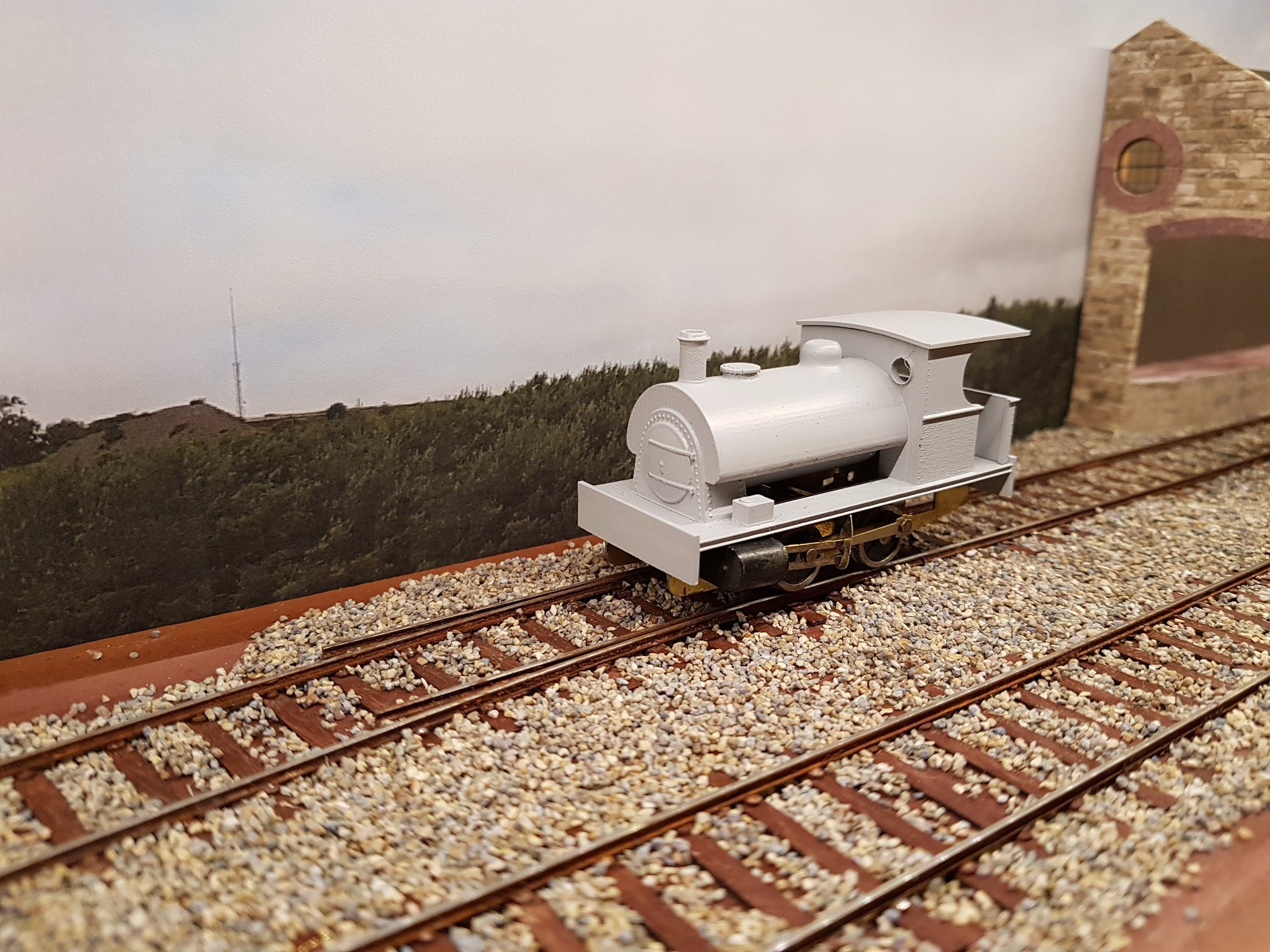
Alas, the RTR version was not to be, however I can fully understand the reluctance to work on a model of this complexity. So it looks like I will have to scratch build one myself after all! I've made a start, but I think there will be considerable time required to complete this model to the highest standards. The finish is a bit stark, however I'm hoping with suitable weathering it will blend down to a more pleasing finish. More as time permits!!
-
Thanks for the comments guys; they are much appreciated. Just to reply to some of the comments raised: This is very evident from the drawings and photos of the locos. From the photos, it looks that the way the rear tanks were constructed the footplate would be quite cramped, so I can have some sympathy for the crew in operating on the stop / start schedule on commuter line. My plan was to complete the 423, learn from the experience, tweak the drawings slightly and build 428 (433 is a member of this class) which seemed like a logical next step and I am quite fond of the 2-4-2T class. I have been using 2D CAD for a number of years for the "real" job so creating plans for cutting was quite straight forward. I do not underestimate the learning curve here as I had to do it at one point also. What I can recommend is a night course in one of the local technical colleges which will get you to a relatively competent level within a short time - this is how I learned as I needed for work. To help practice, it should be possible to get an older copy of AutoCAD lite for small money. I am trying to get a copy of 3D AutoCAD (one of the older versions with disks and licence) so I can continue with the 3D learning I did with the 495 project. What I have found is that the CAM and CNC software is quite complex and while I have got a basic knowledge to allow me to cut basic parts, I would like to fully exploit the benefits of the CNC mill, including some 3D parts. I have no experience in etching, so cannot comment. Milling can take quite an amount of time - a single pass on the cut out above took about 50 mins, and due to settings I needed to re-set the height of the cutter to ensure I cut through the sheet, and run a second pass. So all tolled, it was the better part of 2 hours cutting - I don't know how long etching takes, but I'm quite happy as it is faster and more accurate than cutting by hand. For me, it means I can sit down at the bench and assemble the parts knowing they fit, or should do if I drew it correctly. It also means, I can make repeat models knowing they will be of the same standard. However, there are lots more locos in the GSR fleet which could be built instead of repeats!?! More shortly Ken
-
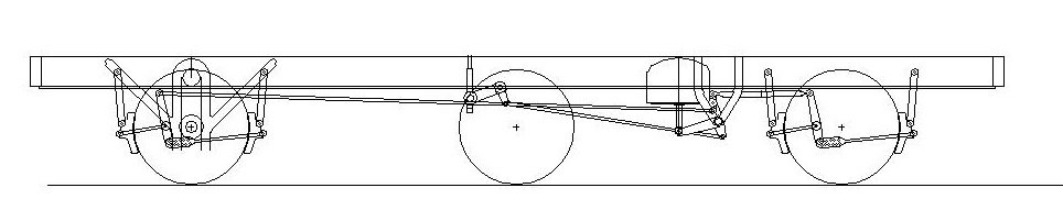
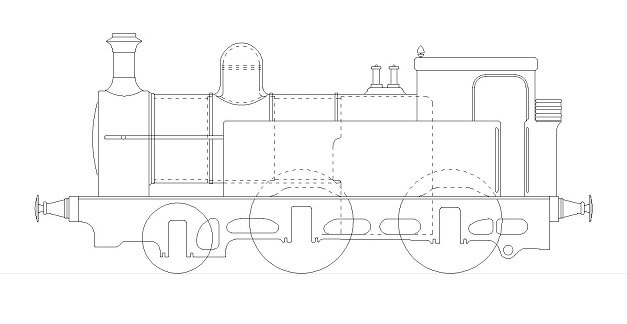
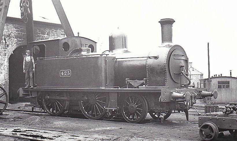
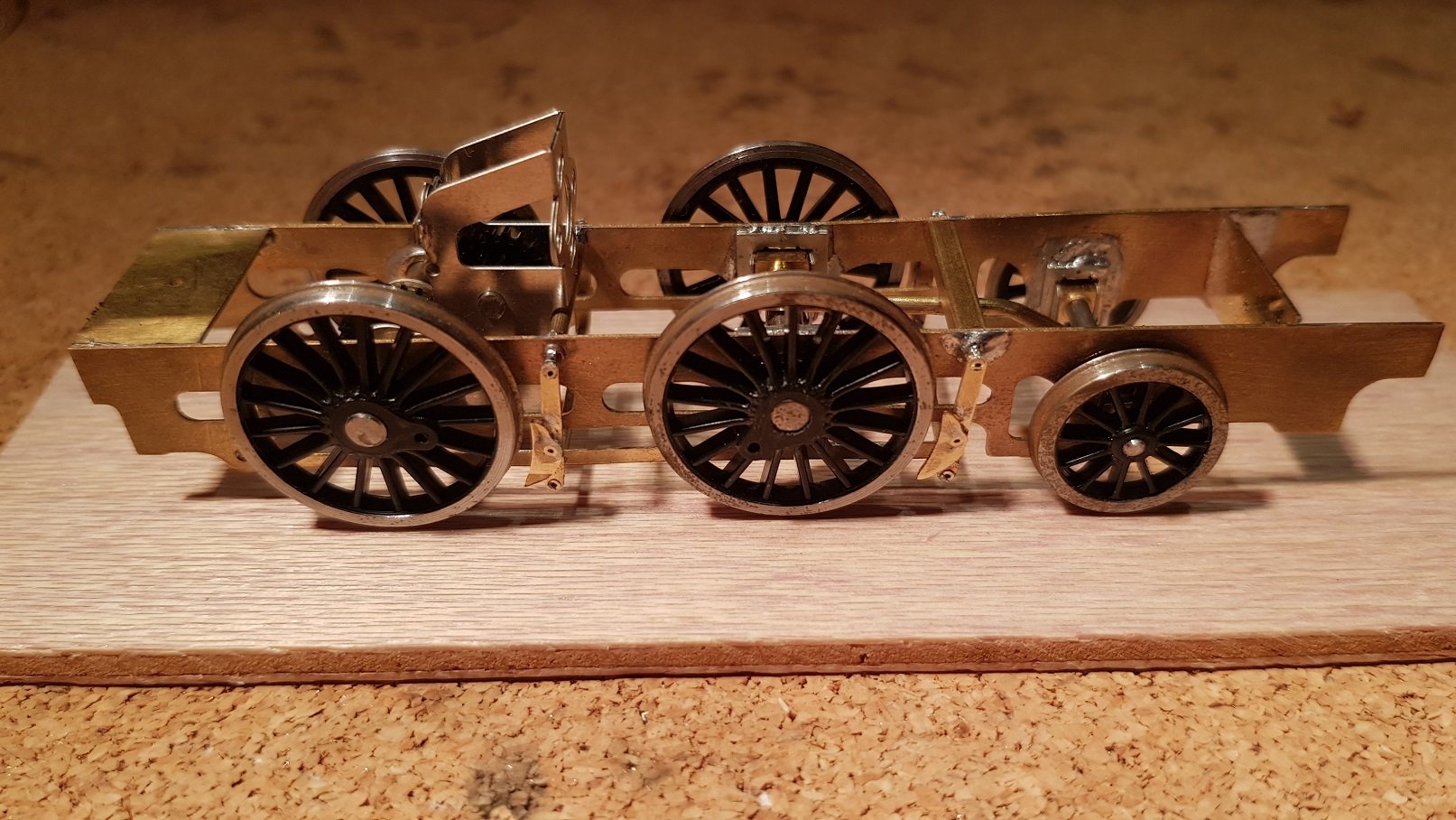
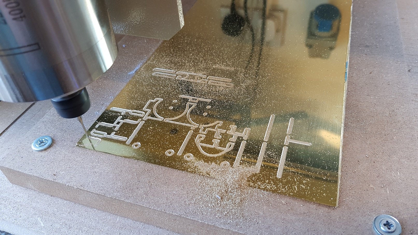
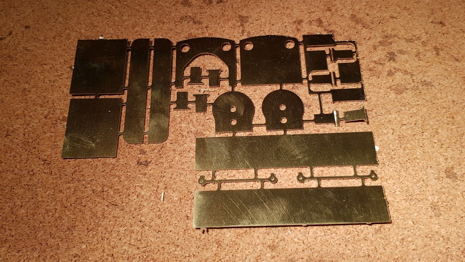
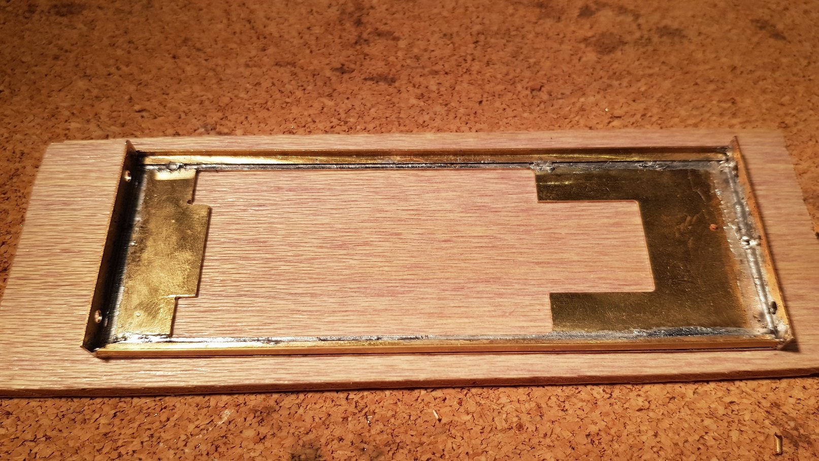
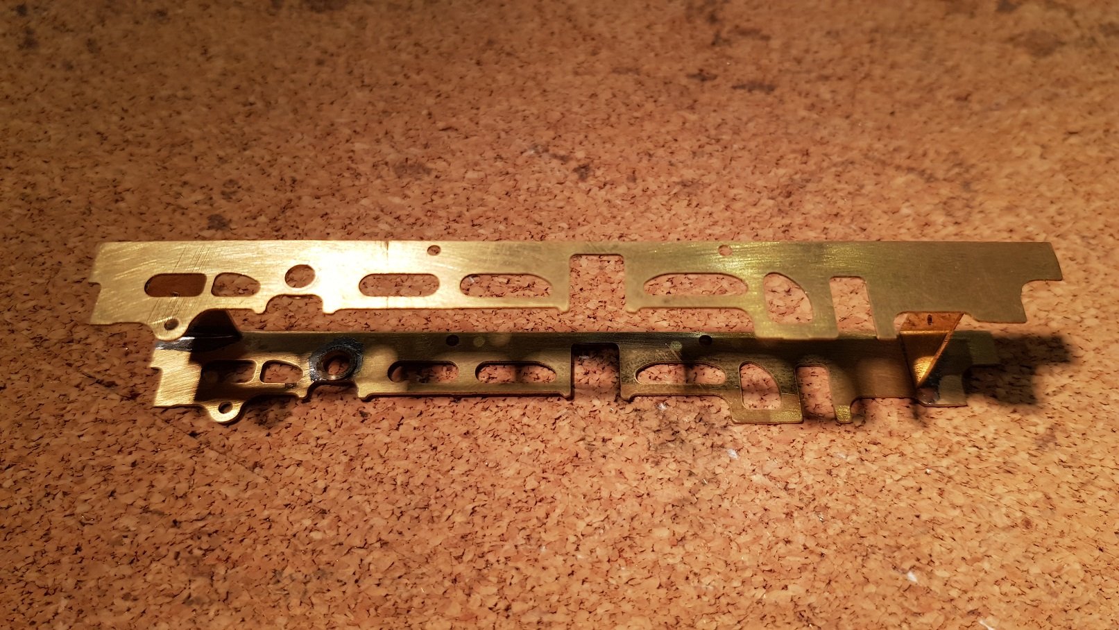
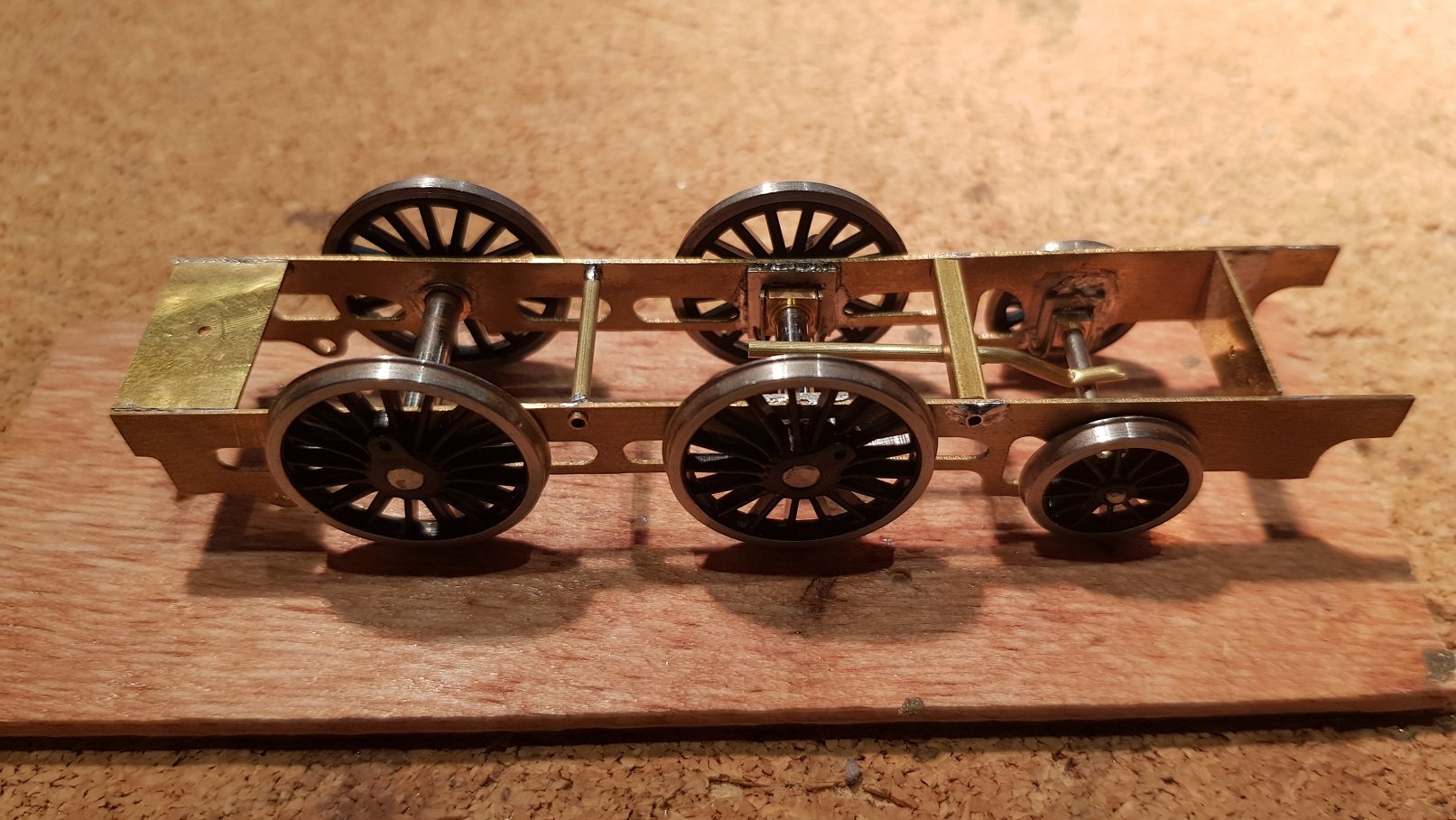
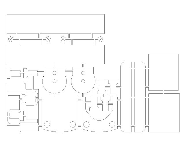
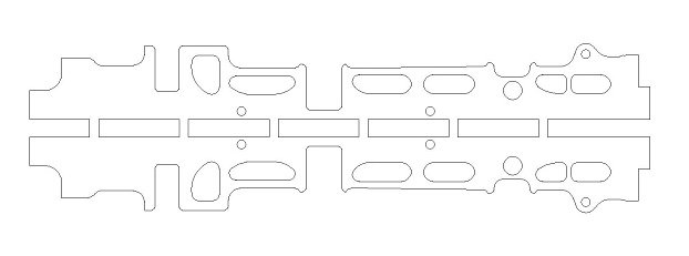
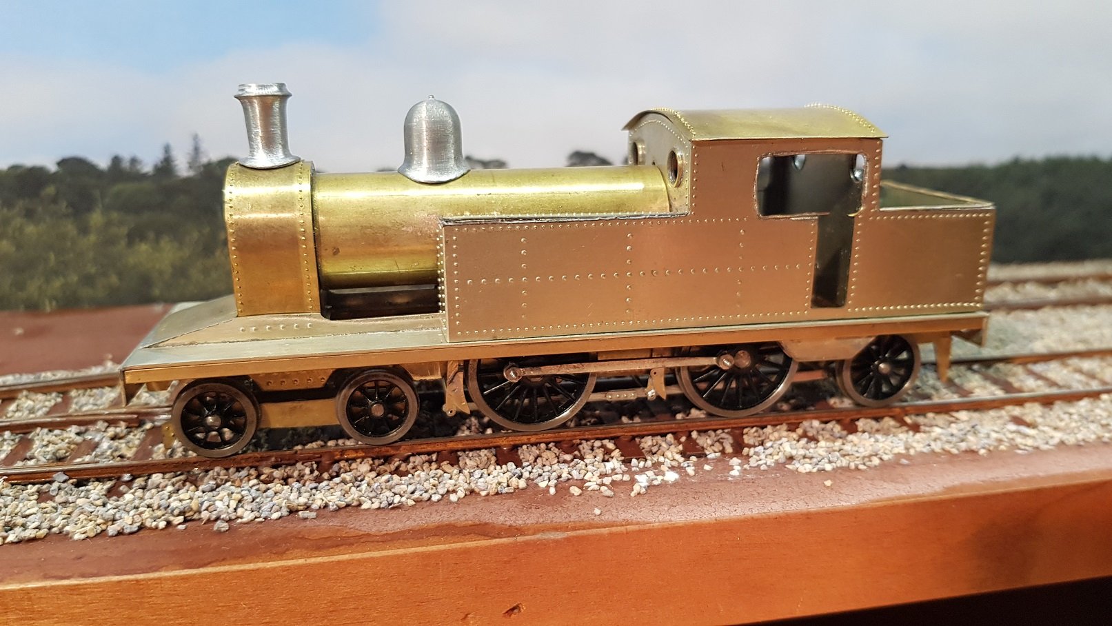
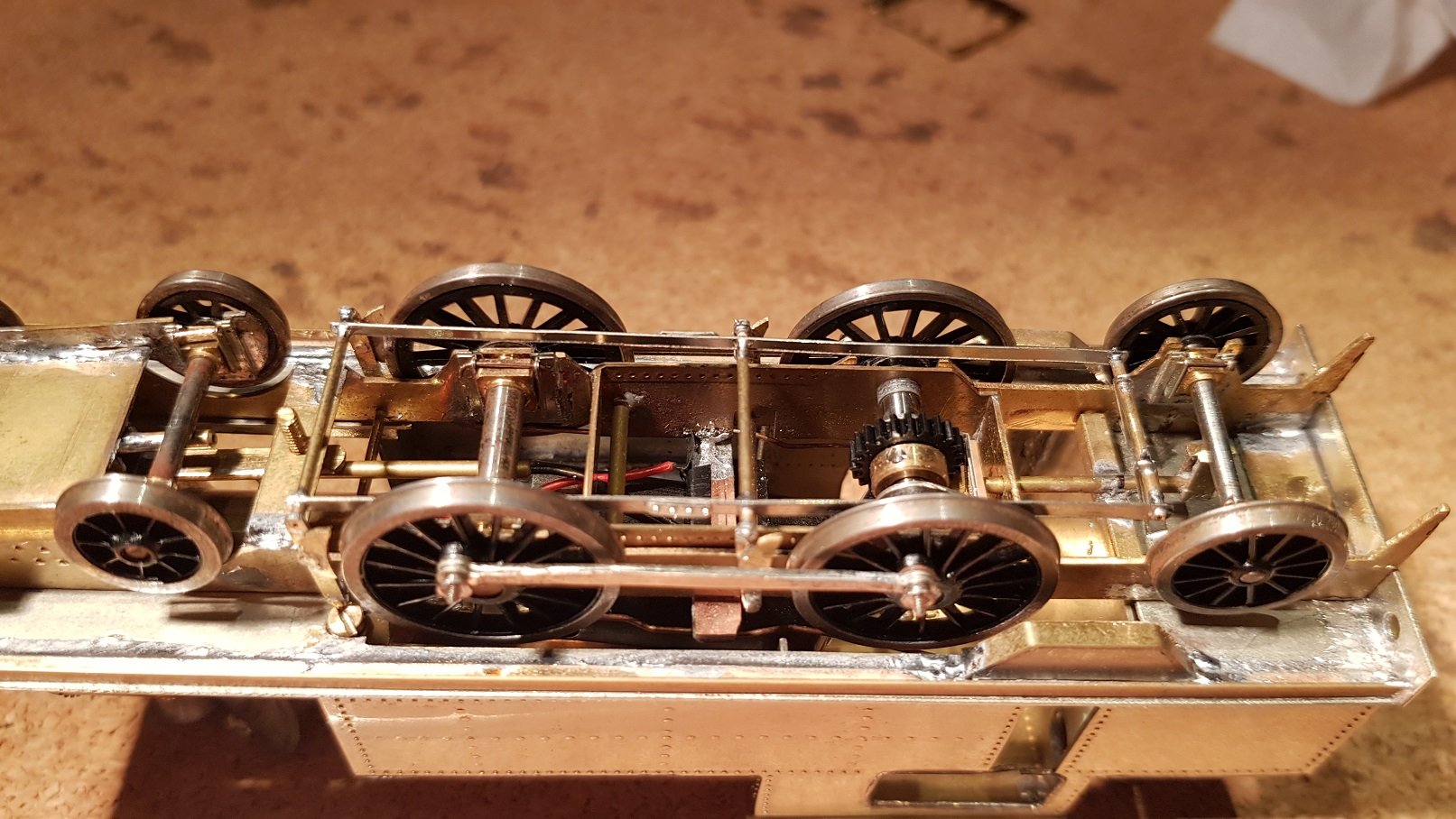
Class 423 Build: Another project on the workbench at the moment. I know the 458 is nearing completion, and the 495 is sitting there awaiting some attention, but a new toy has prompted me to try out a new loco. This time, another DSER tank in GSR guise. Class 423 a 2-4-0T used on the commuter line however they were not highly regarded by the GSR, their comment being "these engines being obsolete in every way. They are slow and high in coal consumption". Not withstanding these comments they ran from 1891 to 1955, so they can't have been all that bad. They also saw service on the Cork - Bandon line, so conceivably could be seen on any Irish layout. Photo credit to Mike_Morant Collection Nice tank engine with good proportions and large driving wheels for their size and proposed use on the commuter network. The difference with this loco is that it has been designed for cutting on the CNC Mill. I mentioned toy above, but this cannot really be considered a toy - the learning curve is quite steep and the software requirements are considerable. 2/3D design Package (AutoCad or similar), Conversion software to generate G-Code (MeshCAM in this instance) and something to drive the servos on the mill (Mach 3 for this mill). Each element has a hefty learning curve, and I have only scratched the surface! Anyway, where we have got to is a drawing kindly supplied by the good people at the IRRS (and they are genuinely a very help group of people), was developed as a CAD drawing. From this drawing parts were extracted into a cutting plan - sample below of the frames. So from CAD drawing to G-Code and through the mill using 0.5mm Brass Sheet we get this. I'm really impressed at how good the CNC cuts and how precise the detail is. Frame spaces were also cut out using the mill which helps to ensure accurate spacing. If you looked at my Class 458 build I go through the installation of hornblocks and setting the axle spacing, so rather than repeating that here I will jump to the rolling chassis point. On this model as a simple three axle loco, the rear axle is fixed for the motor and the two front axles are compensated. Rather than building the complex bar and spacer arrangement as per the 458, I decided to simply bend some 1.5mm tube to the relevant shape to set the level of the chassis while allowing both axles to flex. Much easier to tweak the frame levels this way. Next up, brakes and gearbox. Again brake blocks and hangars were cut using the CNC. I need to tidy up the brake rods at the rear and tie them into a faux crank assembly. Next up, footplate. This was constructed in the same way as the 458. All of this brings us to a rather nice rolling chassis. Gearbox is a High Level Roadrunner +. Levels will need to be set for the motor once I get a boiler in place. Next up was the body, so back to the drawing to create a cut sheet for the CNC. Once again translated to G-Code and we start milling. The brass sheet is stuck down to the MDF with spray adhesive. The tabs between pieces are needed to keep everything in place while cutting. An earlier attempt resulted in smaller bits flying around the workshop - not so good, and impossible to find. Once we are finished the cut parts are separated from the MDF to arrive at this: This leaves the parts in a fret arrangement similar to etches, however the tabs are full thickness so they need to be cut out and filed back to sharpen the edges. That's all for now. Off to the Raheny show tomorrow!
-
Well done. It's a super layout and the detail is sublime. I find it difficult enough to keep locos moving on my small layout at home, so trying to get them to perform in front of the public really adds pressure. Perhaps one day, I may venture out with a layout; most likely to embarrass myself!! Best of luck with the future outings. Ken
-
I was considering a scratchbuild of that loco, but if you guys are proposing a RTR version, i shall direct my efforts elsewhere and wait for your creation with anticipation.
-
My preference is for the Acrylics also, specifically Vallejo Model Air Humbrol 27 - Vallejo Model Air 71.047 Grey Revell 78 - Vallejo Model Air 71.048 Engine Grey I am proposing to use Vallejo Model Air 71.110 Dark Grey as a base with drops of white mixed in for highlights for my locos. Hope that helps Ken
-
If you ever needed a good photographic example of a heavily weathered loco, this has got to be it! That image just oozes character and a hard life......
-
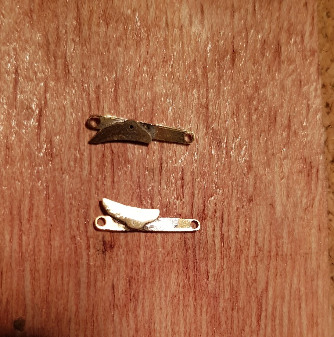
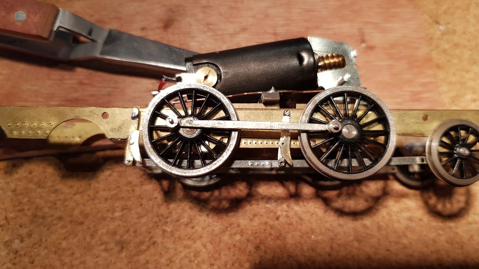
Brake time! Well after the break, there was some work done. I had drilled the chassis to take brake hangers and blocks but needed rods underneath. Brake hangars & blocks were machined out of 0.5mm brass- I'm moving into the CNC realm at the moment, so this was good test. Parts machined well and cut out of tabs to ensure they did not go flying on the CNC (earlier attempt did not go so well!) Parts needed tabs trimmed off and filed back to complete; hence shoes are not identical. Shoes were then soldered to the hangars before fitting to the loco. Brake rods were cut from some 0.3mm Nickel Silver and holes drilled accordingly. Spacing is not 100% as the rear brake blocks are too far from the wheel for my liking, so that will need a tweak to get it more realistic. Front and rear brakes were attached using 1mm tube through the pre prepared holes. The bottom holes also picked up some 1mm tube to connect through the rods. The ends of the rods at the cab end needed to be fixed and were fitted with some faux actuating levers which were angled and fixed back to the frames. This secures the rods at three point and holds everything quite rigid given the sizes of the pieces. Rather fiddly to execute, but came together nicely. I added in a faux joint using some of the rod strip with some rivets on it for detail, which turned out surprisingly well. Once the chassis was back together, we get this: Those rear brakes are just a little too far forward. I have two options - fix it, or leave it, as the front steps obscure the view of the front hangars and block, so perhaps it will not be as noticible. Probably better to fix it and it will be right going forward. The 1.5mm tubes which hold the compensation bars (see above) were trimmed back to the chassis and soldered into place which really tidies up the look of the chassis and stops things from falling apart. A view of the completed work from below look like this: Edging closer to completion