Mayner
-
Posts
5,131 -
Joined
-
Last visited
-
Days Won
128
Content Type
Profiles
Forums
Events
Gallery
Blogs
Everything posted by Mayner
-
http://www.britishpathe.com/video/railway-modernisation 1:39 Still in use in the 1960s the granddaddy of tracklaying machines "The Morris Tracklayer" was invented by the MGWR civil engineer in the 1920s and a relaying train built. The design was licensed to Morris Cranes in the UK and a relaying train built for the LNER. After the Amalgamation the MGWR train was used mainly for track lifting on the Midland rather than relaying for the singling of the Main line during and lifting the Western Branches. The machine was basically built to quickly catch up on the arrears of track maintenance after WW1 & the troubles rather than a cost saving exercise
-
Freightliner traffic to Ireland was originally shipped through Holyhead to Dublin and Belfast ports. The Dublin Freightliner terminal never had a rail connection despite being at the end of the Alexandra Road Tramway and talk about a connection. IE operated two return Freightiner trains on the Belfast-Dublin line for a short time in the early 1990s when Freightliner closed Holyhead & cancelled the Dublin sailings and concentrated Irish traffic on the Liverpool-Belfast sailings. The Belfast-Dublin Freightliner traffic was lost to rail when Freightliner traffic returned to Dublin Port. Some photos of typical Freightliner formations on the North Wales Coast Line in the 80s http://www.penmorfa.com/Archive/nine.htm
-
 The UK rail privatisation was more tied up with neo-Liberal theory that idea that the private sector would make a better job than public sector at anything from sweeping the streets to running hospitals and prisons. Much the same thing happened in Australasia and South America with state owned railways either privatised completely or loss making passenger services opened up to competitive tender. Personally I don't have an issue with the Department of Transport opening up passenger rail services up to competitive tender, in a similar manner to the LUAS and intercity and regional rail services in many countries. http://www.transdevna.com/Rail.aspx Commuter, regional and Intercity rail services are likely to require some form of subsidy regardless of Irelands population density or size of regional centres. Comparing Irish services levels with parts of the UK and Europe with similar population density would assist in establishing a benchmark. Rail services in parts of Scotland, Wales and East Anglia come to mind. L
 -
The Irish Government cannot have it both ways in accepting over £500m in EU Structural Funding to upgrade the railways as part of the deal for signing the Maastricht Treaty in 1992 and then looking for a get out clause on implementing an EU Directive that potentially may open IE up to competition. I suppose IE could do a DB and bid to operate rail services in other EU countries.
-
CIE management in the late 49s seem to have been heavily influenced by American practice with a powerful twin engine Sulzer design for the Cork line and a single cab Bo Bo design for freight. The selection of a Sulzer engine and Metropolitan Vickers electrical equipment was a wise choice at the expense of a high axle load. With the right choice of bogie these locos could have been a real success. It looks like the Sulzer Twins were intended to replace steam on the Cork line which would have been a propaganda coup for both CIE and the Government in challenging Ireland image as a backward place, after all this was the era of the big infrastructure schemes that eventually transformed the Republic from an agricultural to a manufacturing and service economy. Going back to the multi engine Gen-Set idea for the 201s the biggest challenge and cost is likely to be the need for a complete frame up re-design of the electrics and control system. The Gen Set idea is similar to the production Detics, where a complete power unit and generator is maintained by the manufacturer or their service agent rather than the railway. Its hard to see the idea flying with the entire class of 201s, it might be a viable options for locos allocated to specific duties such as IWT, Coillte or Tara. A multi engine loco could be shut down to one engine for shunting or running an empty freight, though an electronic traction and engine management system with the present engine would probably achieve the same result.
-
The thirsty two stroke EMD power units may be on the way out, Electromotive lost market share to GE & other builders in recent years. Perhaps Caterpillar have developed re-powering kits for EMD locos since taking over Electromotive.
-
The Oriental version of "luck-penny" the Chinese manufacturers tend to quietly sorts out the problem at their own expense without admitting liability and throws in a substantial discount off the next order for luck.
-
Most likely 3-4 weeks before shipping, once I have signed off on the BSSGV roof and revised the BSO duckets.
-
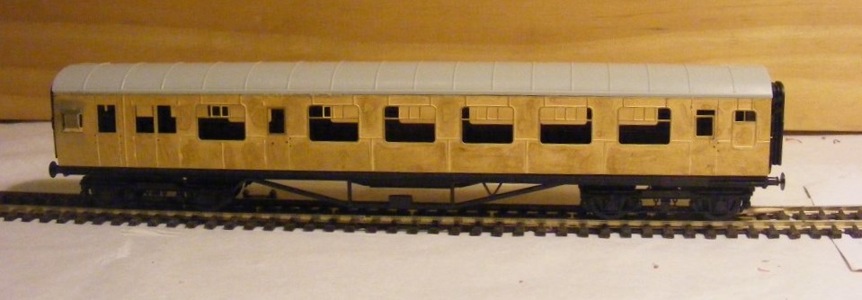
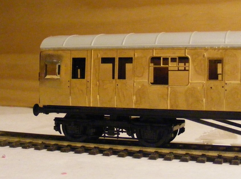
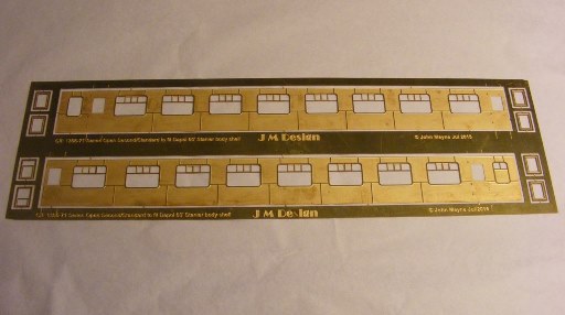
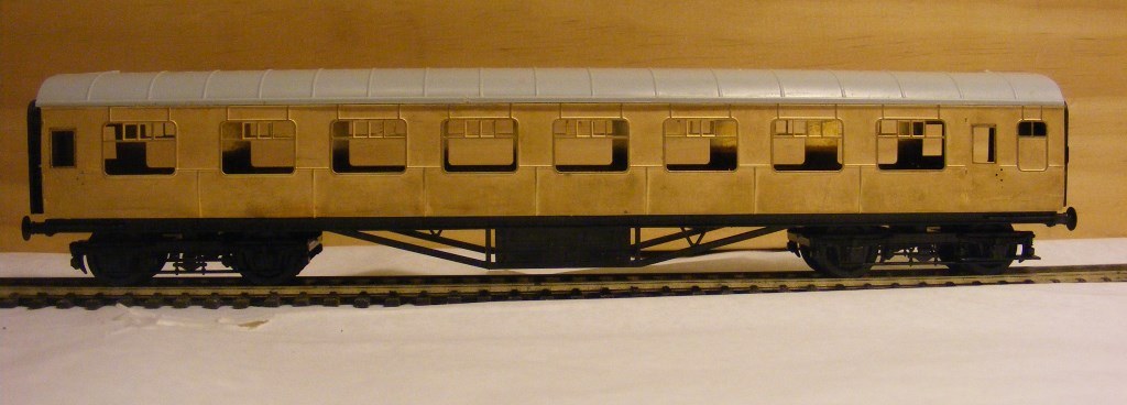
The etches for the SO & BSO sides and production order of MGWR Meat Van & Horse Box arrived last week, the sides and roof hatches for the BSSGV is expected during the next two weeks. The kits and sides should be ready for shipping during the next two weeks. I am looking at options to simplify the assembly of duckets or lookouts in the BSO as they are a tad fiddly. 1356-71Open Standard 1904-08 Brake Standard Open [ATTACH=CONFIG]19591[/ATTACH] I followed Comet Kits instructions for fitting brass sides to RTR coaches this tie and fixed the roof to the bodyshell with polystyrene cement before cutting out for the windows and the interior. [ATTACH=CONFIG]19595[/ATTACH]

-
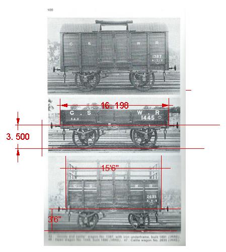
Hi Alan It looks like its a good example of believing half of what you see and very little of what you read. I have a collection of GNR & MGWR wagon diagrams but no GSWR heaven forbid. I imported the photos into CAD set the dimension between rail and buffer centre as 3'6" and let the CAD programme calculate the length over headstocks with interesting results. [ATTACH=CONFIG]19563[/ATTACH] Its likely that wagon design varied a lot between the companies until common standards for wagon types and running gear was developed by the Irish Railway Clearing House in the early 1900s Later GSWR cattle vans were 14' long and became the standard GSR cattle wagon up to the introduction of the longer KN which had vacuum brakes and run at up to 60mph.
-
That Laminate really looks striking. An untarnished A Class and a solid rake of Laminates would have looked clean streamlined and modern compared to the existing stock. CIEs brave but unsuccessful attempt at a 1950s streamliner http://streamlinermemories.info/?p=946. Just might have worked had access to 2 pack paint technology.
-
Its possible that CIE may have been trying to copy the look of an American streamliner and break away from the traditional railway greens and lakes with the 'silver" finish. Its likely the locos and coaches were finished with a clear laquer or varnish to seal the surface and provide some damage/scratch resistance, but was totally unsuitable for the harsh railway environment, both unpainted aluminium and stainless steel will eventually turn black given the right conditions I use Tayima AS 12 Bare-metal Silver aerosol for the vans with a clear sealer, with suitable red decals by SSM. I have tried various aluminium and silver finishes and found the AS 12 most suitable with good scratch resistance before sealing. The Laminates & 4w vans seem to be the only coaches introduced in unpainted aluminium, the Park Royals seem to have been introduced in green with silver bogies.
-
The drop down doors on open wagons are designed so that they are clear of the railhead/inside the loading gauge to avoid a West Ealing style situation http://www.railwaysarchive.co.uk/eventsummary.php?eventID=135. The beet opens were unloaded in the beet factory's by high pressure water jet, possibly moved with the doors down wonder if there is any archive of the unloading on youtube
-
A traffic in raw milk from some of the producing counties to the processing plants might develop if some of the larger dairy companies like Kerry, Glanbia or Dairygold were to amalgamate and centralise processing at a small number of plants. All that's need is a siding at a collecting point, a siding at the processing plant, some flat wagons and suitable ISO containers http://www.teara.govt.nz/en/photograph/21401/milk-trains. Butter, cheese and meat were important traffics for the railways the old companies had special ventilated wagons for butter and meat traffic, reefers and insulated containers were used when the remaining traffic was containerised in the 70s. Up to the 1960s cattle traffic was pretty much from the breeding counties in the West as stores to be fattened in the East or on the hoof to the UK. Meat processing took off in the 50s with rail served (almost) plants such as Grand Canal Street, Roscrea and Leixlip ( Leixlip & Hazlehatch as railheads). Roscrea had a cattle bank with a race leading directly into the meat plant and gantries for loading containers. Rathkeale and Dromad had gantries for loading containers from the local meat works.
-
Dave. Great to see that the model of Carlow Signal Box still survives. Built about 35 years ago for the first MRSI O gauge layout, there was also a model of Enniscorthy and Cahir station buildings
-
Its possible that some wagons had wooden and others steel floors. The wagons dumped at Liffey Junction in the early 80s all seem to have had wooden floors, in somewhat poor condition after being used as spoil wagons for the DART. There was a piece in Irish Railfans News of the floors of wagons in fertiliser traffic being painted in epoxy paint to resist corrosion, which would make sense with a steel floor. In the early 60s there were rail linked fertiliser plants in Dublin (Gouldings), but also plants in Foynes and in Wicklow. NET seems to have supplied raw fertiliser in bulk to Gouldings and the Wicklow plant when the Shelton Ammonia plant first came on line. Wagons in fertiliser traffic would have run sheeted as you did not want to risk a train load of ammonium nitrate getting wet.
-
It looks like Merrion Street may soon be faced with similar decisions about the future of Iarnrod Eireann " In view of the capital funding and operational subvention necessary to maintain and operate our rail network, together with the levels of revenue generated from the network, the current situation with regard to rail is not financially sustainable. The need to ensure value for money must be central to future rail policy. Department of Transport, Tourism and Sport paper "Investing in our transport future A strategic framework for investment in land transport" Interesting the paper indicates that the road user is a nice source of revenue for the Exchequer. Which collects over €4.8 billion a year in tax and excise duty from the road user and spends around €1.32 billion a year (capital & current) on road and rail transport and infrastructure.
-
Not just Ireland and the UK Governments seem to be taking a very hard look at the future of the railways. NZ Treasury urges Government to consider closing down most of rail network http://www.stuff.co.nz/business/70115591/treasury-urged-government-to-consider-closing-most-of-kiwirail The railway carries around 17 million tonnes annually about over a 4000Km system at roughly 3 times the freight traffic density of CIE in the 60s & 70s. Low prices and poor demand for commodities like coal, logs and dairy products is adversely effecting railway profitability and Treasury loses patience and pulls the plug. The whole business feels like deja vu, massive Government investment in rail like the British Rail Modernisation Plan, CIE in the 50s and AMTRAK in the 1990s result in failure and retrenchment.
-
De-regulating road haulage in the early 1990s probably had a greater influence on the run down of IEs freight division than the new roads. Up to the 1990s competition with CIE for freight traffic was restricted under regulations intended to protect the GSR, basically customers had the choice of using CIE, a handful of Licensed Carriers or having to buy their own Fleet of trucks. IE more or less gave up on Sundries traffic as Irish and Multinational logistics companies entered the market, container and bulk traffic held up but costs increased and the railway continued to loose market share and become less relevant as the economy expanded during the Celtic Tiger Years. Judging by experience in other countries any revival in railfreight is more likely to be driven and financed by large customers like port, logistic and mining companies than the Government subsidising IE to run specific services. The biggest obstacles to railfreight in Ireland seems to be that its probably quicker, cheaper and easier to send high value freight from Ireland to destinations in the UK & the European Mainland by road than rail and difficulty in finding a customer that can regularly load a 100TEU train. The Metroport services are bit like Waterford or Belfast building inland ports in Clondalkin. Kiwirail is contracted to run 4 -105 TEU (35 wagon) trains between the port of Tauranga & Southdown Auckland daily. http://www.port-tauranga.co.nz/images.php?oid=3009 Auckland Port recently built its own internal port in South Auckland with a shuttle rail service to reduce congestion in the port and act as a buffer to allow ships to be loaded and unloaded quickly. http://www.poal.co.nz/facilities_services/facilities/rail_exchange.htm
-
One of the underling problem is the loss of experienced railway staff and managers since privatisation. Many of the more experienced engineers mangers have either retired or ended up working overseas. Re-locating the Network Rail head office to Milton Keynes did not help staff retention either.
-
A week chasing trains during the school holidays.
Mayner replied to Mayner's topic in Photos & Videos of the Prototype
No such luck the closest I got to a railway line in the 60s & 70s was sneaking away to take a photo of 5C in Ennis while my parents were shopping in Ennis while on holidays in West Clare in 73 Film was rationed for family photos strictly no trains. The father was a fisherman and eventually got to understand about 15 years later that we had a lot in common after a fruitless search for the Ammonia and Fertiliser trains on the South Eastern, though we did manage to bag the afternoon down passenger in Rathdrum -
The West Clare does not seem to have been completely put off by the 0-6-0Ts and went back to Bagnall in 1907-8 for No11 Kilkee a 4-6-0T. After a series of 0-6-2T & 2-6-2T locos the West Clare settled on the 4-6-0T arrangement in the early 1900s. Although built by Hunslet No 1 Kilrush was supposed to be very close to No 11 including the unusual Bagnall-Price valve gear http://transportsofdelight.smugmug.com/RAILWAYS/IRISH-RAILWAYS/NARROW-GAUGE-LOCOMOTIVES/17846666_q858X4#!i=1512097327&k=kDQf3RZ&lb=1&s=A.
-
A week chasing trains during the school holidays.
Mayner replied to Mayner's topic in Photos & Videos of the Prototype
Coaking coal not in great demand at the moment with China cutting back on steel production. -
The only locos specifically built for an Irish railway company that I can think of were the four 0-6-0Ts supplied to the West Clare in the 1880, which were too light & underpowered for the line. Much later one of the LMS Jinties 7456 supplied to the NCC was a Bagnall
-
Came across this a week filming trains last year during the winter school holidays. Mostly filmed day and night on the outskirts of Christchurch Days and on the Midland coal line classic GM & GE power