David Holman
-
Posts
4,359 -
Joined
-
Last visited
-
Days Won
117
Content Type
Profiles
Forums
Events
Gallery
Blogs
Everything posted by David Holman
-
3D printed baseboards a new one on me. Given the size of the project, would have thought that a 6mm ply or MDF top, with softwood framing would be fine. If you mean laser cut baseboards, these are rather splendid, but very expensive compared to making your own.
-
Thank you kind sir!
-
Thank you both! Seven feet seems to be a standard height for post war vans both sides of the water. The width of the doors would be helpful, as everything else can be worked out from that, so yes please.
-
Lots of pictures, but can't seem to find any dimensions for the classic H. Have the Alphagraphix Bulleid underframe, so know length and width, while presume height of body was seven feet? Anyone got a basic drawing, please?
-
Really interesting and certainly reflects what I have seen of 3D printed models. Indeed, the only smooth finish I've witnessed have been those done by Mark Clark. He advertises in Narrow Lines (7mm NG Society Magazine) and as a Chatham Club member has given several demonstrations to us. Mark has experimented widely with different 3D printers as they have come on to the market. However - and this remains the big caveat with 3D - even a small item can take half an hour to print and this grows exponentially with size, while the start up cost for something like a loco body is around the thousand pounds mark from a commercial point of view. Am sure there are others out there doing just as well too. For me, batch building in plasticard, or resin casting from my own masters are still preferable. Indeed, done carefully, the finish I've got from resin is excellent, you just have to make sure the air bubbles come to the surface and are pricked out with a fine reamer. Resin picks up the finest surface details, including putting in wood grain with a glass fibre brush. It is cheap too. £40 worth of resin makes a lot of wagon sides and ends. Check my CVR brake vans on Fintonagh. Note, this is not a sales plug, I only make stuff for myself, I mention it merely to suggest there are homespun alternatives worth looking into. At the end of the day, we choose what we want to do and all power to the 3D and CAD modellers, who are opening up new avenues to explore. Likewise laser cutters and the like. Etched and laser cut kits are light years ahead of hand drawn stuff of the last century and I for one am very grateful. Enjoy what you do, including solving problems along the way - the latter is a given in our hobby methinks!
-
Know a professional modeller who gets good results with rattle can primers sold in Poundland stores. Erratic supplies apparantly, but worth seeking out.
-
Some fabulous stuff on show here!
-
The Bishops Castle Railway always has me salivating, not least because it was SO decrepit, while the track plan at Lydham Heath is another favourite and superbly done by Barry Norman in S, of course. As for the beautiful Carlisle, was there a prettier 0-6-0? Shannon comes close for me, but then I'm somewhat biased. Meanwhile, those MGW vans were quite something. Shame there are not many photos of them.
-
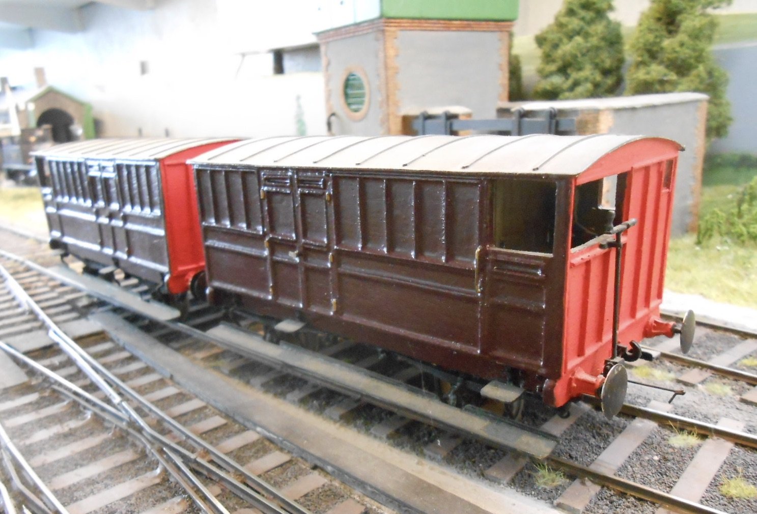
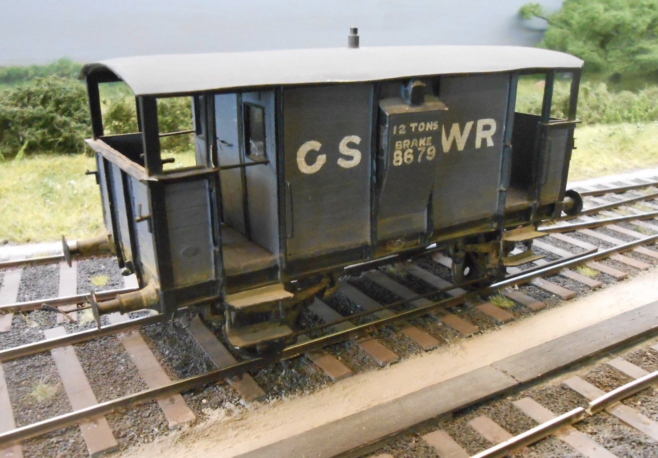
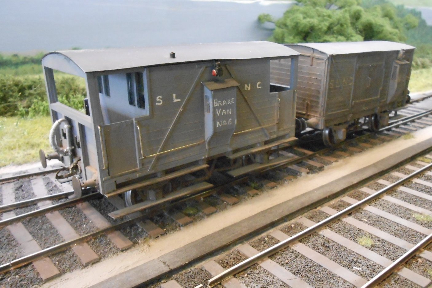
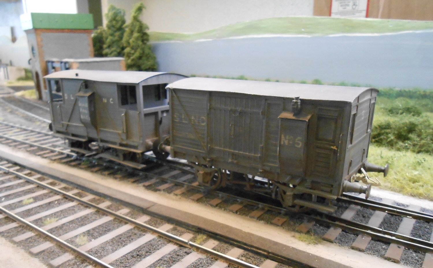
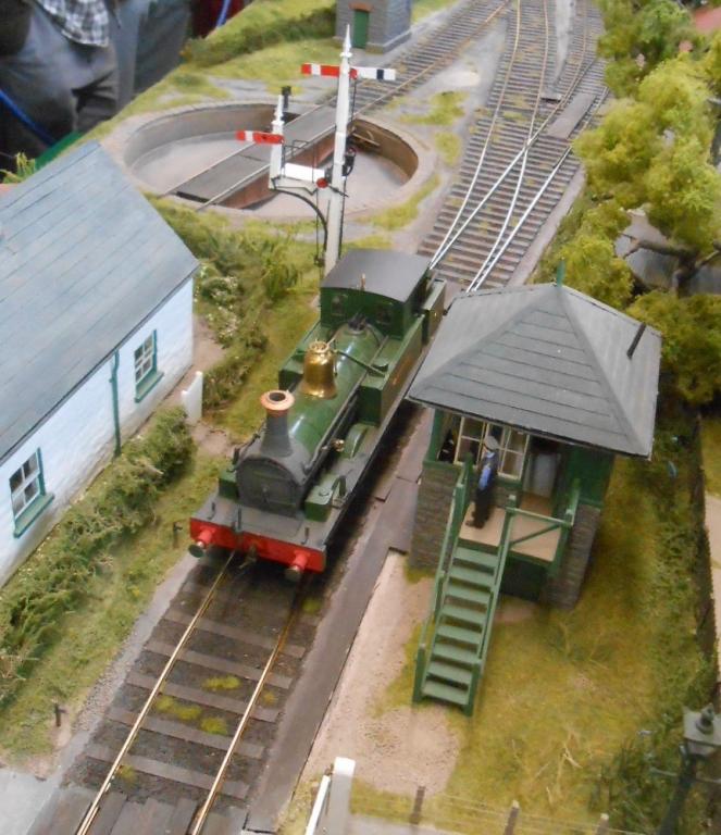
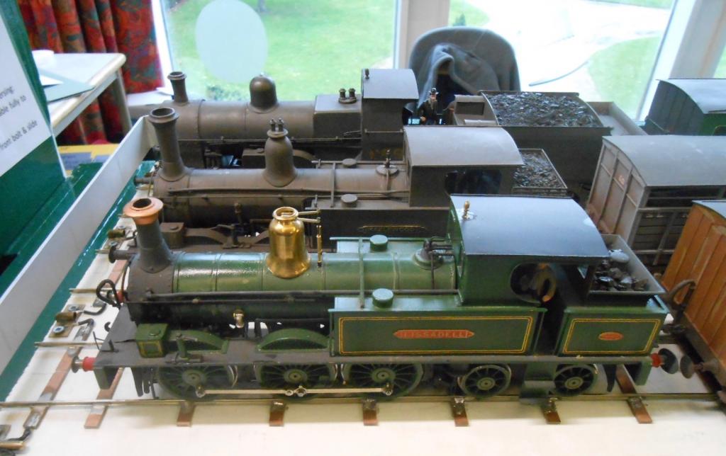
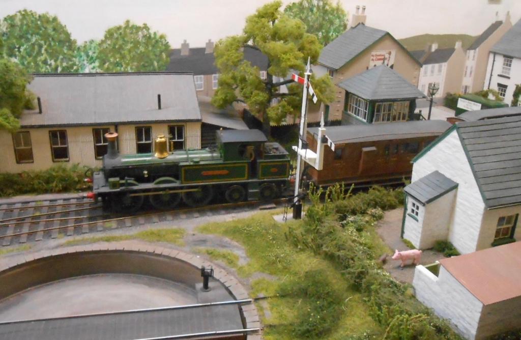
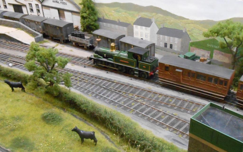
Was going to add this to my workbench thread, but decided it might be interesting to open it out, not least because there have been so many interesting contributions during Lockdown. Essentially, I need at least a couple of new brake vans for Belmullet, mainly because I mostly have SLNCR types from Arigna Town. That said, I was fortunate to acquire three goods brakes from Castle Rackrent and these will form the start of my 1900s period. However, for my 1950s scene, I could do with something non-SLNCR as well, especially as Belmullet is deemed to be a blend of the latter, plus WL&W, MGW and GSR/CIE. So, what have I got? Well, as you can see from the photos, it is a slightly eclectic collection. First, there are examples of all the SLNCR types - two of the drovers' vans [2 & 3], plus road van number 5 and the more conventional double balconied No 6 - the latter with a badly warped roof you will no doubt see... I will probably split these so that two get used in the 1950s and two back dated to the early 1900s. One of Richard Chown's vans is a GS&WR 12 tonner. Its a bit battered, with pieces missing from the roof and balcony, plus a couple of broken steps. It is also rather dirty, so needs a fair bit of TLC. It is interesting though, in being mostly made from wood. The other two vans are decidedly exotic in their maroon livery and salmon pink ends. As far as I can tell, they are ex Dublin & Meath. This railway was leased to the MGW in 1869 & absorbed in 1888, according to my Railway Atlas of Ireland by S. Maxwell Hajducki. Richard seems to have used both vans on Castle Rackrent as part of the 'mail goods', often with WL&W 0-6-0 Shannon in charge, so this is something I'd like to perpetuate. Quite how he saw the two D&M brakes getting to Castle Rackrent is another matter and would certainly be interested to know a little more about them, both the models and the prototype. They are certainly broad of beam, being a scale 9'4" wide over the body. As for my own latest effort, this is an ex GS&WR ten ton brake. Had been hoping to do a MGW one, but don't currently have a drawing of any, apart from the 20 ton version and the curious drovers' types, which seem to be an enlarged version of the Sligo ones - or vice versa perhaps? Anyway, my 10 tonner comes from the old Model Railways article by Tim Cramer. This shows the 12 ton version, which Tim suggests is easily converted to the lighter type simply by reducing the wheelbase from 11' to 9'6.However, as Leslie's 4mm scale kit shows in our Irish Models section, the 10 tonner is substantially wood panelled, rather than the metal T section framing of its heavier sibling. You can see progress thus far in the final picture. However, and more questions yet, what livery should it be for the 1950s? Photos of the model show it as clean, pale grey, with both GSWR and CIE insignia, which can't be right, can it? As for other types of goods brake, while the GNRI ones seem fairly well documented, it seems to me that information is a bit thin on the ground for the rest. For example, I have photo of one on the Courtmacsherry tramway, while as for WL&W types or indeed MGW, Ernie Shepherd's books aren't terribly forthcoming - just two paragraphs for the latter is all we get. So, will await replies with interest and especially the D&Ms and my GSWR ten tonner!

- 29 replies
-
- 13
-

-

-
Looking good
-
Snap off blade knives have been my go to for years. Apparantly, it is the tip that does all the work and soon gets dulled, so snapping off for a new one is easier than sharpening. Foam board for some reason a real villain here. That said, I often use one of my Exacto blades on foamboard - the long, triangular sort seem to work especially well.
-
A case of cleanliness before godliness where model railways are concerned! Know what you mean as have been slowly going through all my stock too and not just the locos. Wagon and coach wheels were all dirty enough to blacken a cotton bud soaked in meths - one per wagon required. They run much better now too and are not spreading fresh dirt around. Then I looked at my GS&WR brake van from Castle Rackrent. At first, I thought the wheels had been blackened, but it was a coat of grime getting on for half a millimetre thick - no doubt the result of many years hard work!
-
Walker Diesel Class F - ECMbuild in 4mm for OOn3
David Holman replied to murrayec's topic in Irish Models
Indeed - I sometimes wonder if it would be easier to model in black and white! The diesel is coming on rather well though.- 136 replies
-
- 2
-
-
- class f
- west clare
- (and 1 more)
-
Quite a combination, must be two of our finest. Mike is of course the craftsman behind Judith Edge Kits, while Ian Rathbone is a master painter. His book on loco painting and lining sits alongside Martyn Welch's Art of Weathering as two of my most referred to books, not least because both are easy to read and apply. Wonder if Martyn will eventually get to do a bit of weathering on Maedh?
-
Fabulous. Many thanks John.
- 42 replies
-
- 1
-
-
- kit building
- wagons
- (and 5 more)
-
Looking at the early picture of the E class, am amazed how much difference the original chimney makes to the overall appearance of the loco. Were there any major rebuilds to the class, apart from the Waterford cab/bunker changes? Reason I ask is that my own J26 is eventually due to be backdated and while I'm happy to replace the chimney and do a repaint, there is little point if it needs a larger boiler etc. If it reappears in the Tyrconnel range, would certainly recommend it. A simple, easy build, mine took just 40 hours including painting and weathering. Runs well too.
- 42 replies
-
- 1
-

-
- kit building
- wagons
- (and 5 more)
-
Ace kits are the work of Bill Ascough. Advertises in the modelling magazines and has quite a large range of loco kits that are good for the experienced modeller, but not a beginner, I'd say. Nothing Irish, as far as I know, but does do kits for the Woolwich 2-6-0s. Indeed, in the past has hinted at doing the GSR versions.
-
Help! My static grass won't stand
David Holman replied to gm171 kk's question in Questions & Answers
I now use a small jeweller's screwdriver instead of a nail. To help the grass stand up, I go over the area treated with the vacuum cleaner nozzle, covered with a handkerchief. Find 12mm fibres too long, 6mm is about the limit, but you can make longer grass by going over the same area twice. -
Apply the three foot rule and a bit of weathering and you have the makings of a nice new project. Certainly look good to me.
-
Arigna Town - this week's scenery
David Holman replied to David Holman's topic in Irish Model Layouts
Here's the post I did in 2016, after the Manchester show.
-
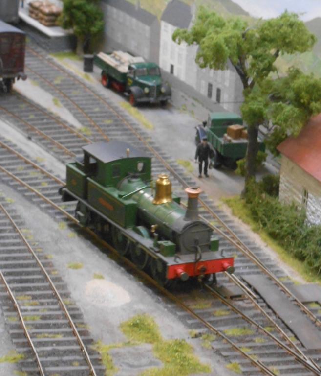
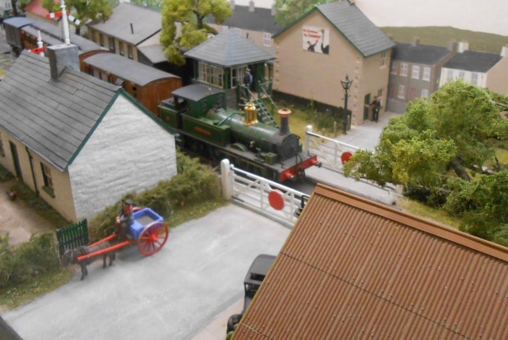
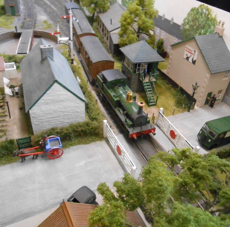
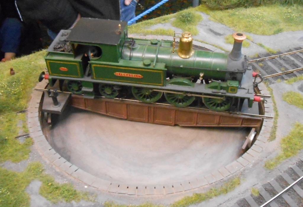
Only just caught up with this thread again. Interesting to get livery details, not least because my own Small Tanks, Fermanagh and Hazelwood are in need of some TLC, mostly just paintwork, but a good excuse to correct a couple of errors... My name plates are black, rubbed with wet and dry to reveal the brass letters - a whole lot easier than painting the raised letters red! Tempting to do red background and raised brass letters therefore and Sir Henry can be the same. Also useful to see the SLNCR lettering on the tank sides as Fermanagh will be back dated to early 1900s eventually. That said, when I had the pleasure of meeting Richard Chown at the Manchester show a few years ago, and we ran his version of Lissadell on Arigna Town. This was in lined green, with a polished brass dome. Anyone got any ideas when this livery gave way to black? Will post a pic of Lissadell later.
-
Not sure the Swilly would work in 7mms scale on 00 track. It only equates to 2'4 and the Swilly locos were big. That said, the garden could be a good way to try and represent the wide open spaces. Given unlimited time and wealth, doing it to 10mm scale on 0 gauge track would be my own preference, though it ain't gonna happen....
-
Walker Diesel Class F - ECMbuild in 4mm for OOn3
David Holman replied to murrayec's topic in Irish Models
Does things properly, does Eoin. An example, nay inspiration to us all.- 136 replies
-
- 3
-
-
- class f
- west clare
- (and 1 more)