David Holman
-
Posts
4,359 -
Joined
-
Last visited
-
Days Won
117
Content Type
Profiles
Forums
Events
Gallery
Blogs
Community Map
Everything posted by David Holman
-
Sorry to disturb the slumbers Tony, but such things are easily fixed. Looking at the photo, the slope appears to be 45 degrees or so. I'm certainly no engineer, but have a feeling that anything steeper would be in danger of collapsing on itself, which is why retaining walls are used. There's some nice thick foliage on that embankment, so longer static fibres, topped with scenic matting and scatter will replicate nicely.
-
Just a thought, Tony. Some of the embankment sides look rather vertical. Don't know the area at all, but grassy slopes would rarely be more than 45degrees in the real world and even a 30 degree slope is actually 1 in 2 so steep! There again modelling allows us to go steeper without much detriment to how things look, though near vertical faces would either be rock faces or require retaining walls.
-
Agreed! Can't see from the photos ( and maybe it doesn't work as well in 4mm as 7mm), but a trick I learned from Gordon Gravett's is to file a 'flat' on each tyre where it touches the ground. Imitates the real thing and just helps the model sit better, giving it a bit of mass.
-
Certainly is Ken - and now I have my GSR locos book, I can follow the background to your growing fleet too. A fine collection, so keep the posts coming.
-
At Warley, bought " Locomotives of the GSR", by Jeremy Clements and Michael McMahon. Actually, the wife gave me the money for it as a Christmas present. Hence, only really got my hands on it yesterday, but well worth the wait. What a fantastic, encyclopaedic tome!
-
21mm gauge track; the pros and cons?
David Holman replied to jhb171achill's topic in Irish Model Layouts
C&L do both, I believe. -
21mm gauge track; the pros and cons?
David Holman replied to jhb171achill's topic in Irish Model Layouts
As sleeper lengths are the same either side of the sea, then C&L plastic sleepers, as above, would be fine, while Marcway of Sheffield do copper clad sleeper strip in most scales, the latter ideal for flat-bottomed, lightweight track as per Arigna Town. -
7mm scale 101 - a tribute to Richard Chown
David Holman replied to David Holman's topic in Workbench
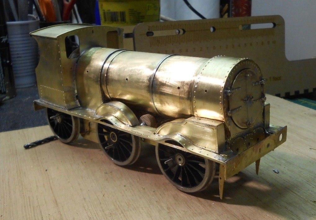
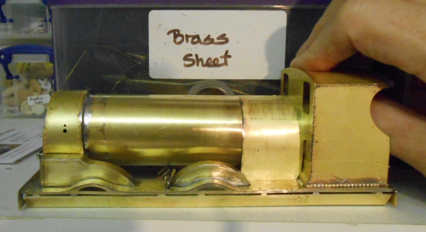
Spent much of the last week faffing about. It all stemmed from the last sentence of my previous post - joining footplate to frames, where it quickly became clear I'd made a right old Horlicks of the bodywork. In the end, I had to dismantle much of it because the body simply wasn't sitting squarely and with the frames being quite flimsy, they distorted when the two were bolted together. Add in the fact that the buffer beam was 2mm higher one side that the other and it really wasn't good... So, first of all strengthened the frames by adding in 4mm brass rods at each end, then added a front to the ash pan. Course, the brass rods lined up exactly with the captive nuts on the footplate, so the former had to be drilled out to take the 6BA fixing nuts. Next had to unsolder the cab/boiler/smokebox and start again - which of course meant the footplate was extremely flimsy, as I'd cut out all the strengthening pieces! All in all, a bit of a b****r and as you can imagine, that wasn't all that was said. Anyway, it did [eventually] get done, but then had to be followed by a substantial clean up as excess solder had got all over the footplate and firebox. Since then, I've managed to add the details to the smokebox doors, though the latter's diameter was about 2mm too small in diameter, so had to make a new one by scribing round the original on some brass sheet and then cutting & filing to shape. The kit only provides etches of the strapping, so the other details had to be source/fabricated myself. The two knobs/handles in the centre are heads from dress making pins, while the top and bottom handles are coach ones. The actual hinges were made up from brass bar and wire - the RSU coming in very handy here. Today, added the splashers inside the cab, plus the etched details provided for the backhead. Fair bit missing though, including gauge glasses, piping, gauges and the like, so will have to see what the spares box contains. Also had a look at the boiler mountings. The dome looks ok, but the chimney that was in the box [turned mild steel] is way too tall, so have shorted it at the base, meaning the latter now needs building up as it is now too narrow. Not sure whether I'll need to get a new one & am regretting not doing so at the Reading Trade Show. The safety valves were made up from two different spares - a whitemetal base and cast brass valves. All these items can be seen sitting, unfixed on the boiler in a couple of the pictures. Given that Christmas TV is [as usual] looking pretty uninspiring, I may well take the opportunity to fill in all the holes from my enforced rebuilding - there are quite a few [!], so some filing and sanding is now needed.
-
Sounds like the makings of a plan, Colin. One that could make a very impressive model and a pleasant change from the norm we see too often in magazines these days. Suggest lots of planning, sketches etc to further visualise the concept and maybe a 'model of the model' as Gordon suggests. Your book of his is the one I meant. Will look forward to hearing how you get on.
-
Fear not Tony, no model railway was ever built without (quite a lot of) mess. And scenery is the messiest of all! However, you are right in that there comes a point when there is no alternative but to have a grand tidy up before starting something else. You may well fine that tool/paint rush you've missed the last few days.
-
What is it about a single photo that stirs the juices? Not sure, bit certainly agree. HC Casserley's shot of a train about to leave Burtonport has spawned many a sketch plan, but sadly, do not have the room to do it justice, especially in 7mm scale. And there's the rub, ten feet is a reasonable space in 4mm scale (I presume), though immediately sets the ideal train length to no more than 40 inches - based on the Iain Rice rule that a train needs to be able to travel three times its own length on the scenic section. Any longer and it won't look right. Still 40" is not bad in 4mm scale, though this assumes your 10' doesn't include any fiddle yards or storage sidings. Ideally, a continuous run, methinks. My own memory of driving the Barnesmore Gap a few years ago, was of a very wild place, with little, if any habitation. Would think that open framed baseboards, to give land above and below the track, would work best. Likewise, fairly deep boards too, with a high backscene and fully enclosed fascia, pelmets etc. Two books spring to mind. Rice's latest, ' Cameo Layouts' and Gordon Gravett's book on Scenics. The first to get inspiration for overall presentation, the second to create superlative ground cover. There's not going to be much in the way of complex track, bit with scenics and presentation done well, it could make a stunning layout.
-
7mm scale 101 - a tribute to Richard Chown
David Holman replied to David Holman's topic in Workbench
Thanks everyone, much appreciated! Especially like John's idea for joining firebox and boiler - far more elegant (and obvious) than my rather botched effort. Likewise Eoin's suggestion for fixing firebox to cab. Unfortunately, fear I may have to solder it all up as a solid unit that end, unless I can think of a way of filling in all the gaps and still make the unit removable. Both methods are now stored away for next time! Also good to know the boiler/firebox was indeed flush, Paul. I have a cast white metal blackhead that may get used instead of the etched bits supplied. Just depends on how it fits between the splashers. Still a long way to go though, for there is a wealth of fine detail to add, plus am still undecided whether it is worth fitting inside working valve gear. At the very least will add dummy motion, just depends on how much is visible once boiler/footplate and frames are attached. -
Know what you mean, a single picture is often all it takes to get the creative juices flowing!
-
7mm scale 101 - a tribute to Richard Chown
David Holman replied to David Holman's topic in Workbench
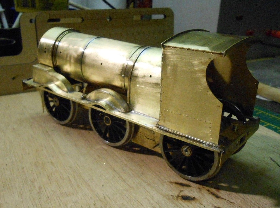
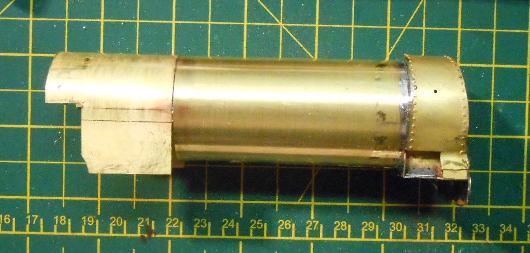
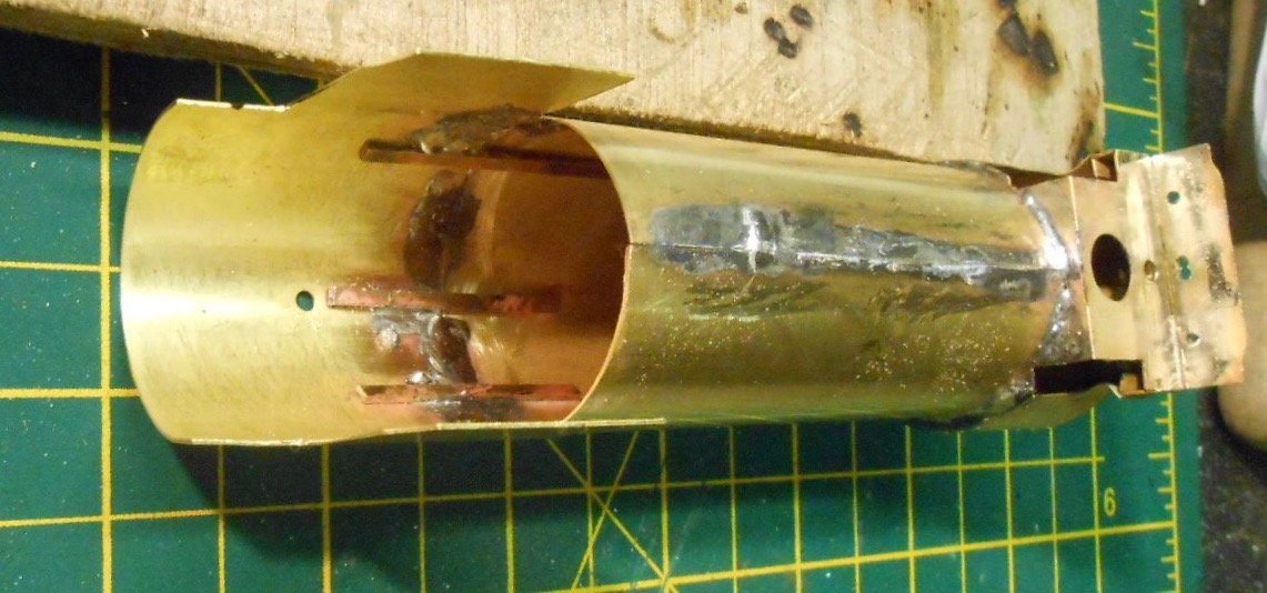
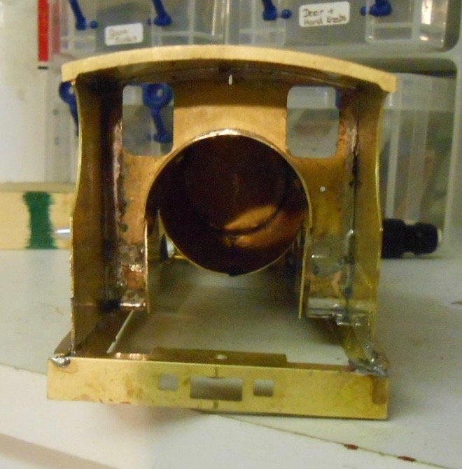
Trouble at t' mill I still like the 101 kit, a lot, but no matter how well things are drawn or how good the instructions, there is always at least one part of a kit that causes furrowed brows and a few new constructions of Anglo-Saxon. And thus it has been today, so any advice welcome - Mayner, Andy, Paul, especially! It is those lines in the instructions you love to hate. In this case 'the shape of the firebox may need adjusting to fit the spectacle plate; after join the firebox and boiler'. Hmmm... Firstly, no mention that the boiler is a piece of rolled brass, that has not been joined. This not a problem, as soft iron florists' wire holds everything in place while you solder up the seam - been there, got that T-shirt. Better to use a higher temperature solder too - in my case 240 degree as opposed to the 145 I use for most things. However 'joining the boiler to the firebox? Is is supposed to overlap? Is it a flush fit? And if the latter, why wasn't a single, rolled piece provided instead? My ability to put things together back to front is well known [to me at least], but it still didn't stop me doing a dry run with the firebox the wrong way round. Eventually, realised [I hope] that the half circle bit goes inside the cab, resting on the two lugs on the spectacle plate [see photos]. Checking drawing and photos, my impression is that the firebox should be flush [not overlapping] with the boiler, so I added three strips of brass to the firebox to help align the two. Again, can only hope I'm right. Fairly confident here, as otherwise, when the boiler is lined up with the smokebox, it slopes downwards towards the front, so clearly wrong. Even so, to get the boiler to sit level with the smokebox, I've had to file a bit of the spectacle plate, in order to raise the height of the opening which takes the firebox. This way, I can [just] get it to sit level, though there are a few gaps that will need filling. This leads to my other conundrum. The smokebox is fitted to the footplate by a captive nut & bolt - ideal in terms of having the smokebox/boiler/firebox assembly removable for painting. The problem is how to bolt the firebox into the cab? Any ideas welcome here, though I fear I may have to solder the who thing solid as I can't at the moment think how I will otherwise fill the gaps the kit [or more likely my bodging] have created. It is still a good kit though, one that is proving both interesting and [mostly] very enjoyable to work with. The basic shape is coming on nicely and [fingers crossed] the body sits well in the chassis with the motor gearbox pretty well hidden.
-
Thanks Paul, not everyone enjoys the Irish scene, but praise from those that do is doubly welcome. No invites further north yet, but suspect that as soon as it goes north of the M25 there will be. Arigna Town has just one more show, a local one in Kent that I accepted ages ago, at the end of January. After that, it is being 'retired' for a while, as I can ill afford to have two exhibition layouts on the go. However, plans are afoot to adapt it eventually, including back dating the scene to include both Shannon, the 101 and various other things I fancy - mainly with a bit more colour, so early 1900s is the plan, but still stuff to do on Fintonagh first.
-
Lovely job
-
Looking good.
-
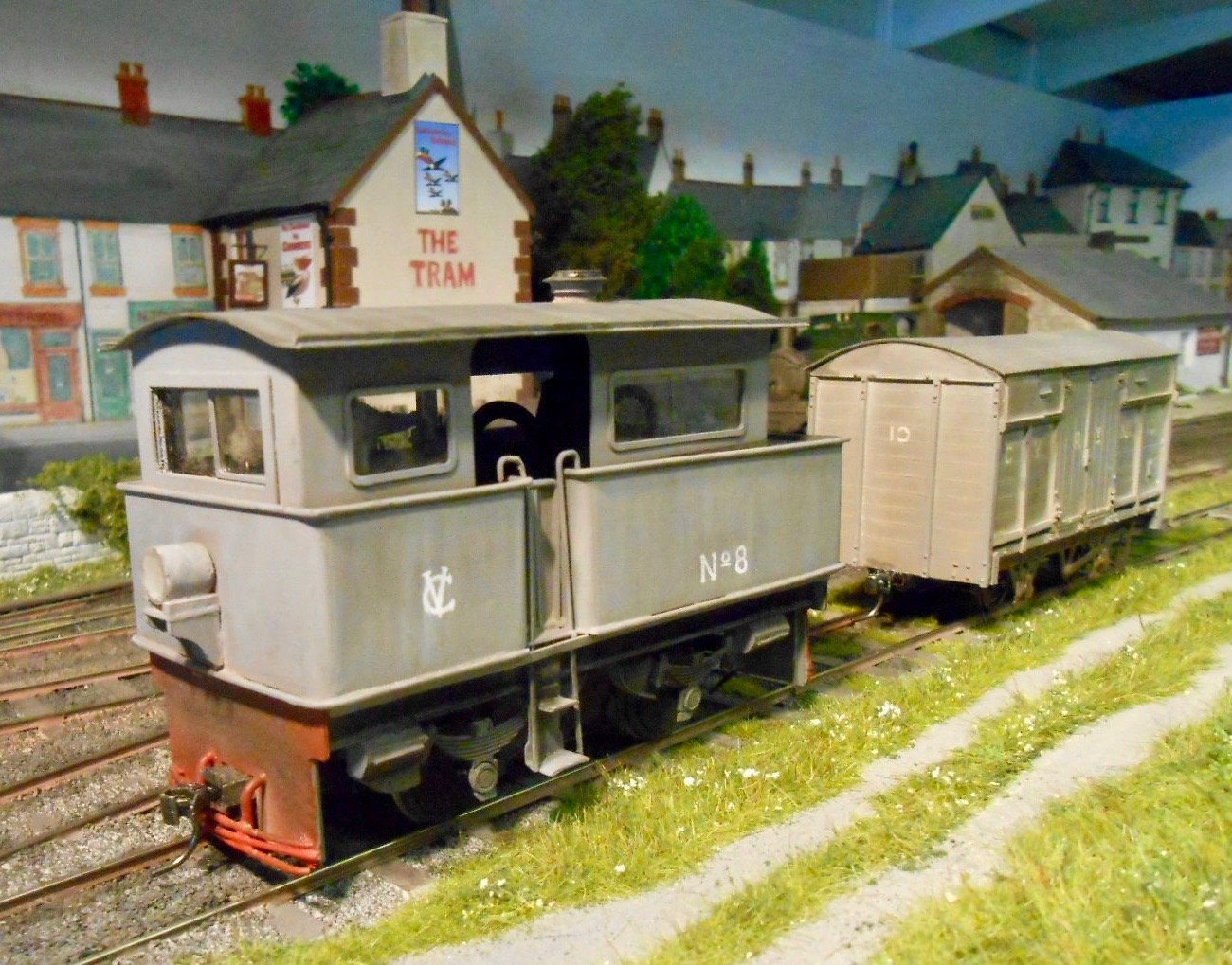
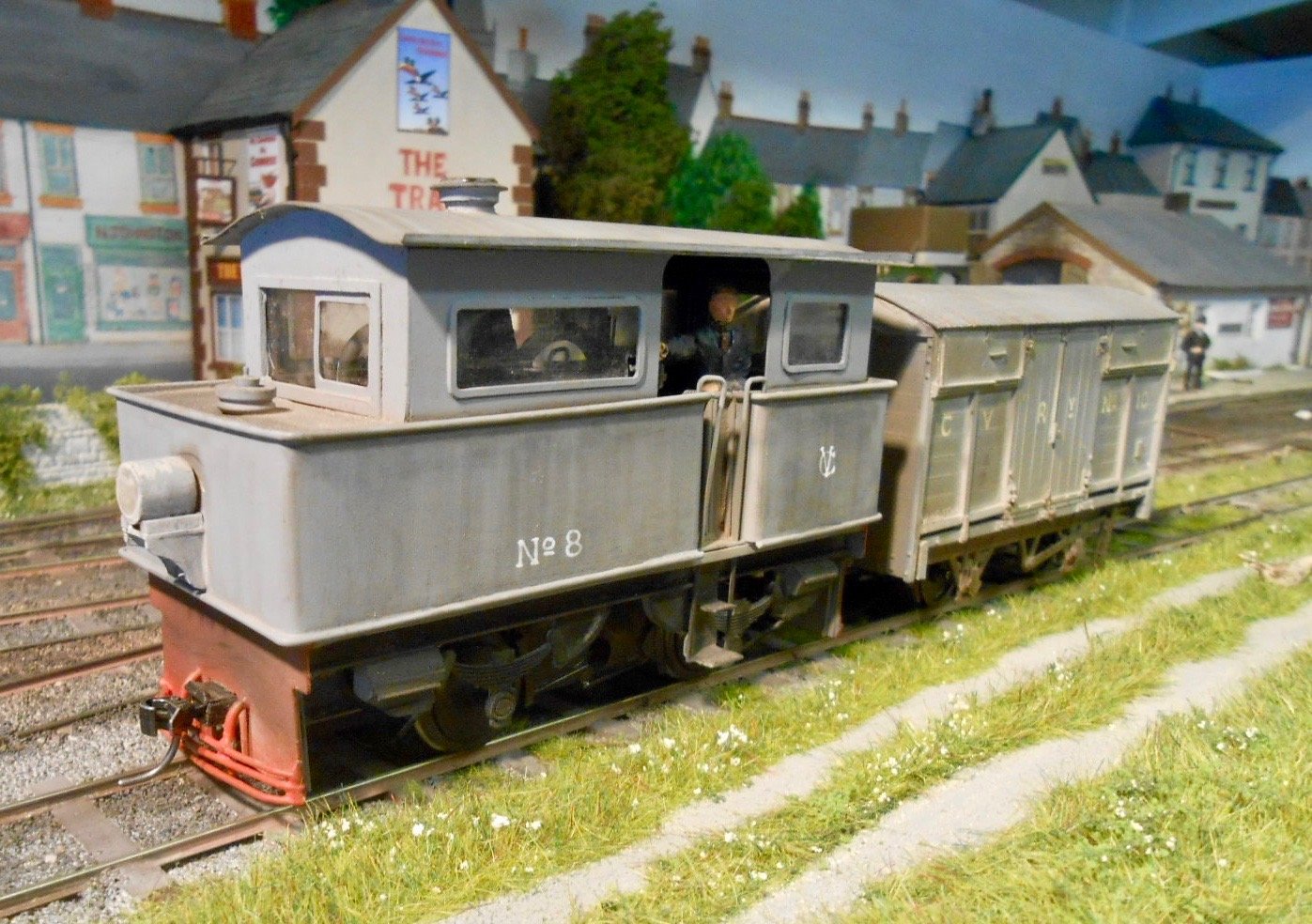
Needed a bit of light relief from the 101, so with the AW tractor nearing completion, decided it was time I finished it off. Mostly it was painting. Started with a couple of coats of Halford's grey primer, then once that was dry, could paint the interior fittings black and the buffer beams red [both acrylic]. Glazing came next, then a single crewman, after which it was time to fit the roof. Lettering is my preferred method of dipping pen with white ink. The assumption is that the CVR did buy the loco, after further testing, so it became No 8 on the loco fleet. Talking to folk, there is feeling that the CVR crews might have scuppered the original deal, as the tractor was intended for one person operation - thereby doing a fireman out of a job. The unusual firebox [the door was in the floor of the cab], may have caused problems too. The photo in Patterson's book shows it to be a fairly grubby condition, so I've tried to replicate this with weathering powders. A word of warning here. Humbrol black weathering powder is pretty strong stuff and if anything, sticks rather too well - creating unwanted streaks when I tried dusting it on. Extensive cleaning up was required to get rid of these, using cotton buds dipped in meths & wiping off the streaks with a vertical motion, to simulate the effect of rain running down the sides. The Humbrol powder is ok on the chassis and mixes well with other tints, but will not be using it on bodywork again - indeed the roof will probably need repainting.
-
7mm scale 101 - a tribute to Richard Chown
David Holman replied to David Holman's topic in Workbench
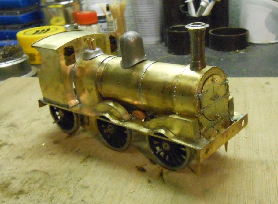
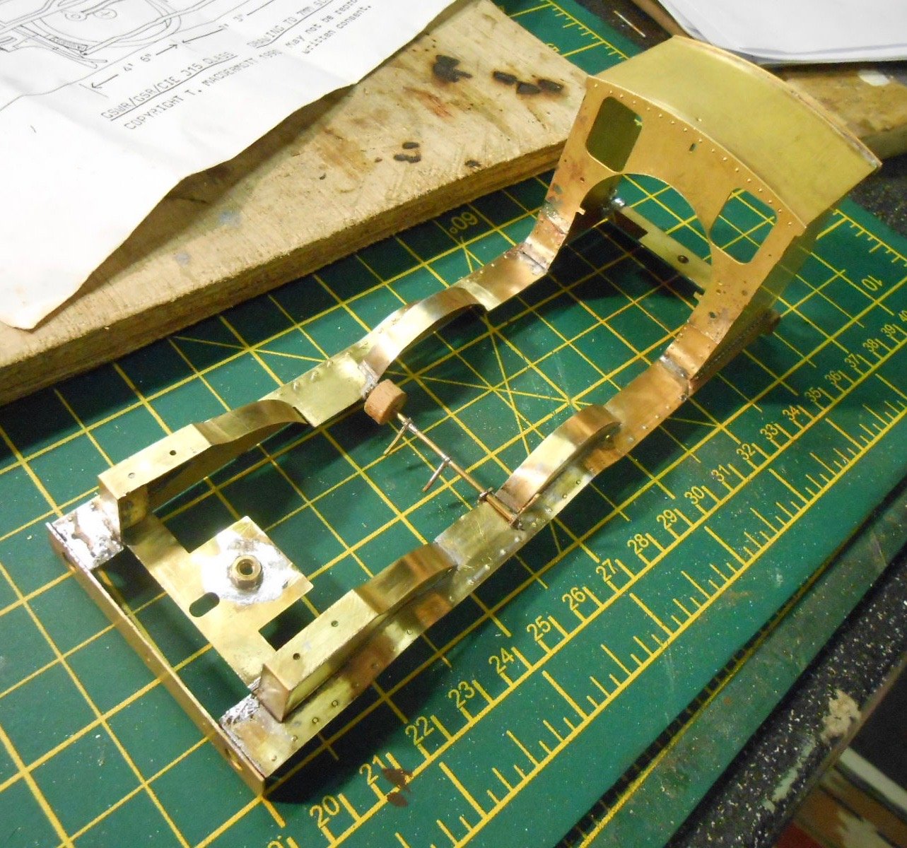
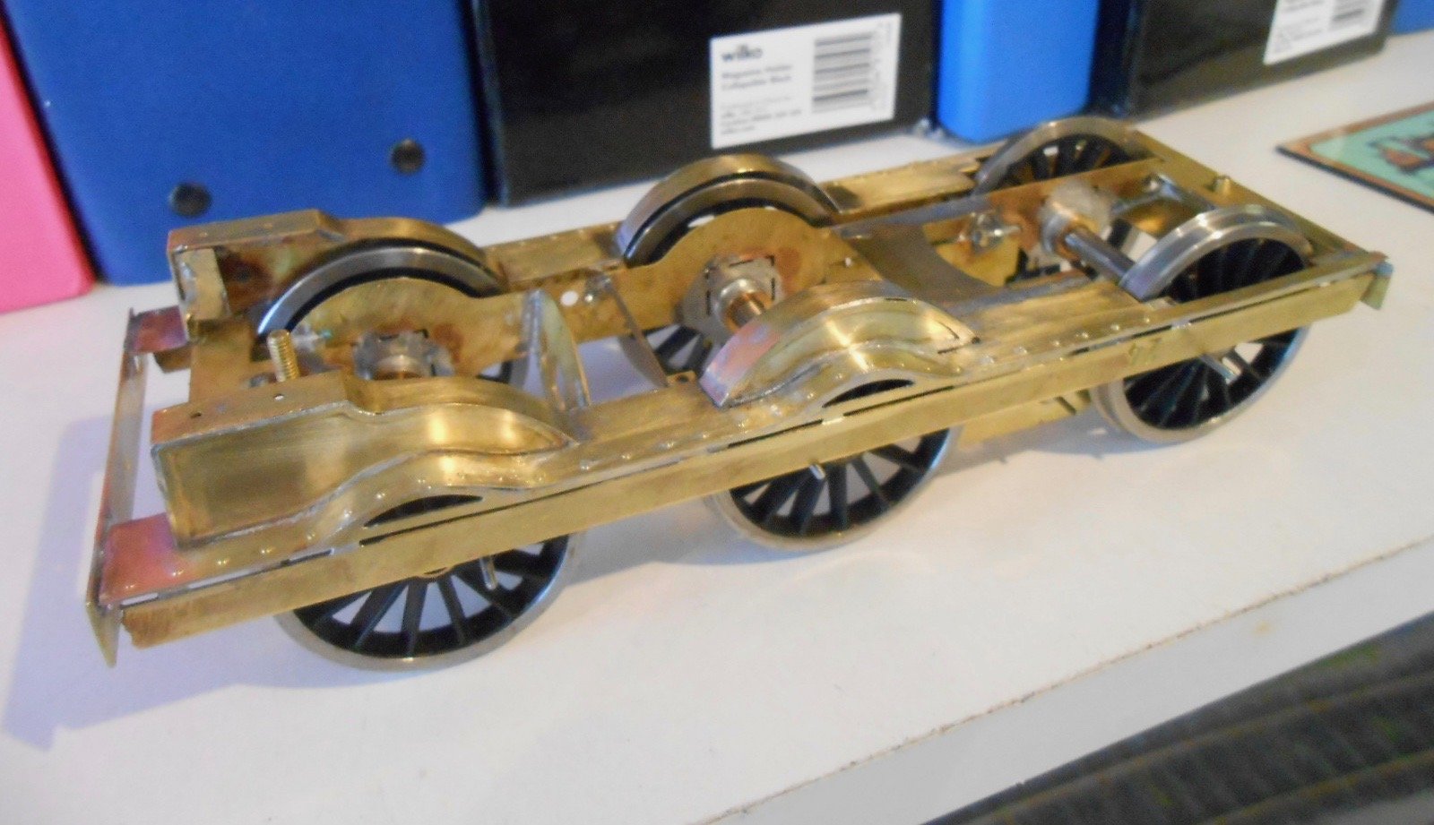
Thanks Paul - Find the history of such things fascinating. Presumably, there was no CAD when Terry created the kit? If so, it was real state of the art for its time & stands up very well indeed against more recent kits I've built. Have managed to get the footplate area built. There curved sections certainly require patience! The latest photo shows it attached to the frames, to check clearances & again appreciate how much tighter things must be for Mayner and his 4mm scale models. Probably less than a millimetre clearance in 7mm scale, so down to fagpaper in anything smaller.
-
The former a will be ideal for strengthening the card weaving, Tony.
-
Extraordinary ambition and vision, while I've seen whole layouts built on the footprint of the control panels. Thank you. Love the shot looking down on the Google footbridge. For me, the signs of a great layout are how many dimensions it has. Not the physical ones, but the visual ones and suspect there are a great many interesting and satisfying views from all angles. One of these days, maybe you're doing it already, you will look at Barrow Street and think, 'Did I really build that?' Eventually, (not now!), it would be fascinating to read about what inspired this opus, how it will operate etc, etc. Many more miles on the journey yet and look forward to each new installment.
-
Good idea. It the same as painting a picture - background first and subsequent layers on top as you move to the foreground.
-
I still like the original method in The Art of Weathering. There is both logic and reality in putting rust on first, then covering it in Maskol, before spraying the top coat and peeling off the Maskol to reveal the rust underneath. Takes longer, but very satisfying. Having said that, the alternative methods look pretty damned good too!
-
7mm scale 101 - a tribute to Richard Chown
David Holman replied to David Holman's topic in Workbench
Thanks John. Credit to Eamonn then. I once built a Gibson GER E4 that had clearly been blown up from 4 to 7mm scale, enhancing, if that is the right word, a fair few dimensional errors. Taught me a lot in a way, because I had to make several new body parts and use rather more filler than I wanted. Early days yet, but the fact that a set of bought in profile milled rods matches the etched chassis is promising. Presumably the kit was hand drawn, unlike the CAD stuff of today when resizing much less of a problem. Just following the instructions for now and will be glad when I've got that footplate finished! -
Continually amazed at how intimate the layout is, with so many details in amongst the [much] bigger picture. Any chance of some more 'distant' views, to see how it is all hanging together?