murrayec
-
Posts
2,718 -
Joined
-
Last visited
-
Days Won
70
Content Type
Profiles
Forums
Events
Gallery
Blogs
Store
Community Map
Everything posted by murrayec
-
Excellent David, Great expansion to the workshop tools, a lathe is a must have item in model building in my view. ArcEuroTrade do a small set of tools- 4mm, which could be suitable for your machine;- https://www.arceurotrade.co.uk/Catalogue/Cutting-Tools/Lathe-Turning-Tools/8pc-High-Speed-Steel-Turning-Tool-Sets Banggood used to sell a lot of stuff for this lathe also! Eoin
-
@skinner75 Thanks, I love restoration work of old machines, motorbikes and cars. I know 'My Mechanics' on youtube, I watch a lot of this stuff and generally stuff like timber frame house building, log cabins, alternative energy...... the list is endless come to think! Thanks for the other links, I was offered an old Harrison lathe of comparable size, I would love to have something of that scale but alas my place doesn't have the space, and my days of working on big stuff are done so the Myford hit all the bells when it was offered. Eoin
-
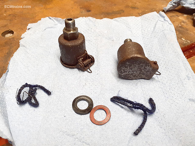
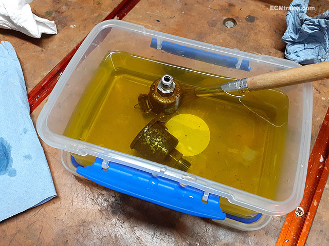
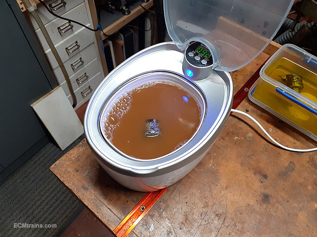
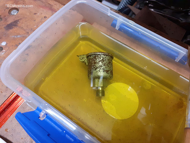
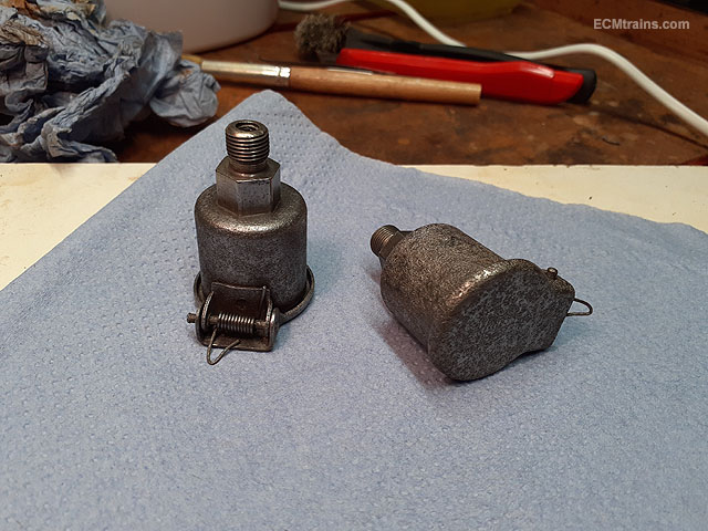
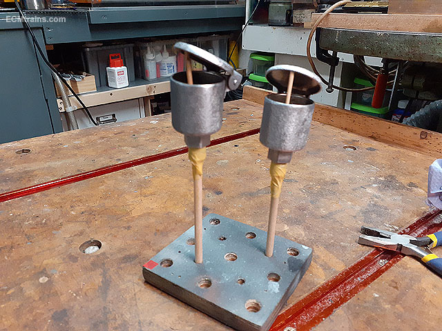
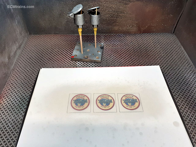
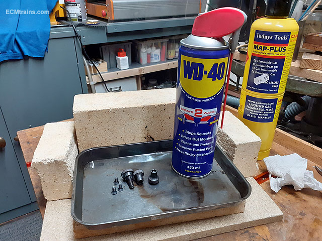
'Rusty Old Oilers' These are the spindle wick oilers, their not that expensive to replace but with the rust removed they are still usable- so this is how I remove rust when sand-blasting cannot be used, I'd like to preserve whatever is left of the chrome finish! Washed in de-greaser. Popped into a strong bath of hot water & citric acid and given a good brush over and occasional wire brushing to help loosen the rust. One should not use a brass brush as it will give the metal a brass tint! steel brush only. Then popped into the ultrasonic cleaner with de-greaser solution for 200sec, that solution was clear when the oiler went in. So repeated this process 3 times- nearly there! If one leaves the parts in the citric bath for to long (like hours) a dark coating forms on the metal surface and the parts will rapidly rust up again! So short periods are best, the parts still come out with the coating which can be removed with the steel wire brush immediately. This coating can be used to protect the metal surface in some situations but does not look very nice! Parts complete and wire brushed, they still look a bit rusty but this is because the acid is still in the pits and still working away- a good wash in the ultrasonic cleaner with clean water does the trick. Cleaned up and wire brushed on the bench grinder, then mounted on a stick for a coating of lacquer to stop them rusting again. Lacquer being applied and while doing this the badge print was give its first coats to the rear of the paper sheet, one can see how the lacquer has gone into the paper and revealed the print on the other side. When the other side is done the badge will be plastic! I'll leave these for 24 hours and apply the finish coats...... Eoin

-

Bulleid's Turfburner - stock that it would have hauled?
murrayec replied to DERAILED's topic in General Chat
According to Mr Shepherd's book on its trial runs to Cork;- October 4 1957 - 5 Bogie Carriages & 1 Heating Van = 165 Tons October 5 1957 - 5 Bogie Carriages & 1 Heating Van = 165 Tons Test runs to Sallins;- September 4 1957 - 5 bogies & 1 van 160 tons September 5 1957 - 7 bogies & 1 van 225 tons September 6 1957 - 8 bogies & 1 van 255 tons September 27 1957 - Five Bulleid design carriages As far as I can remember in reading the book it never went into service, testing never finished, Bulleid left Inchicore with it going into storage?? Eoin -
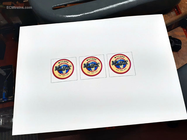
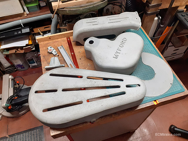
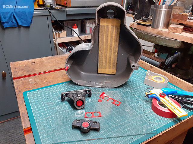
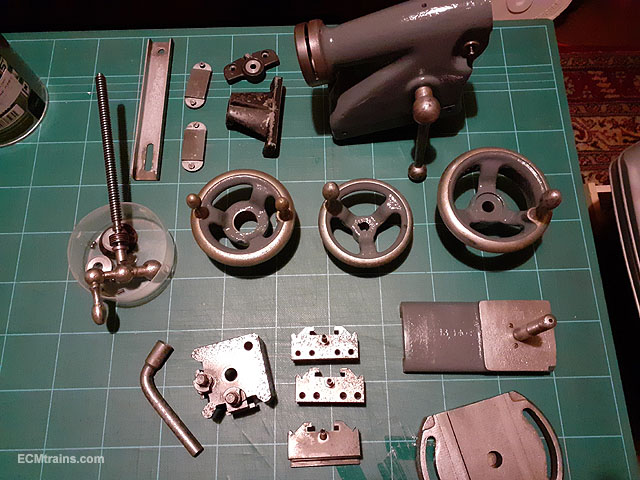
Painting started over the weekend. I'm using Johnston's MDS metal paints on this project, it's a one coat system that can be applied to bare n rusty metal applied by brush or roller, I used a roller but the paint didn't flatten out, I reckon it needs a second coat with a bit of rubbing down first! Black bits were sprayed jet black. Setting up a badge for the pulley casing. Printed off 3 copies of the badge on photo quality paper, just in case of cutting errors! This print will now be laced with varnish back n front which turns the paper into plastic- almost! Eoin
-
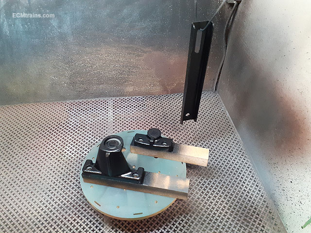
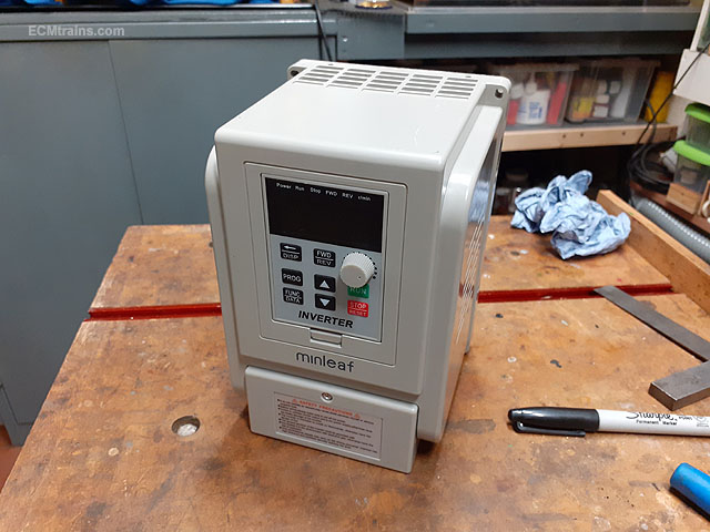
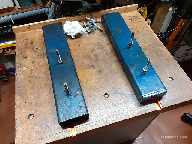
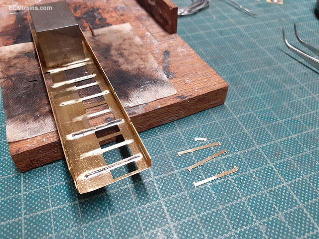
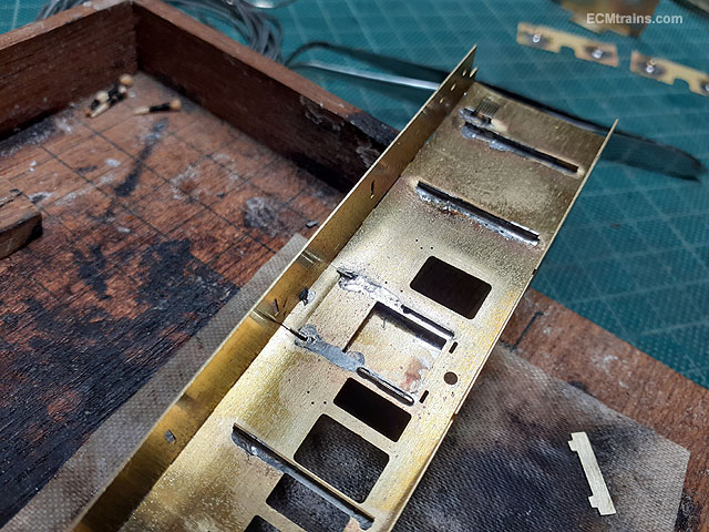
First works of 2021..... The casings and other parts were masked up for the sandblasting, this casing had the screw cutting gear chart riveted to the inside so it was covered up. Other parts with bearing surfaces were covered up with electrical tape- it last better in the blasting than masking tape and I don't plan to blast the inside of this casing- the outside will do. Blasted. The black paint was pretty tough on these parts so I cut it short when the paint was smoothed out and when these parts are re-painted one will never notice. First saw cuts on shortening the existing riser blocks. A second cut was done 40mm in from each end and not all the way through to create bolting down brackets. And then the remainder was cut with an angle grinder to form bolting down brackets to the bench, the idea is sketched out roughly on the right. The off-cuts were trimmed to size to close the box section and will be welded on. I had noticed when removing the lathe that one of the risers was at a slight angle! The one on the right has it's lower lathe mounting stud hole a good 6mm off centre, so when welding I will fill that one, re-drill and tap it on centre. And on Christmas eve the postman arrived with the inverter!! Happy New Year everyone. Eoin
-
It's a horse carriage lamp;- https://www.ponyandcarriage.co.uk/horse-carriage-lamps-carriage-parts-tyre-shop.htm Eoin
-
Dinky
-
'Momentum Button' It's a case of reading the manuals! Here is a link to the problem that Noel referenced to in a previous IRM thread;- https://www.rmweb.co.uk/community/index.php?/topic/89097-beware-nce-and-esu-momentum-idiosyncrasies/ Eoin
-
GSWR/GSR/CIE Six-Wheeled Coaches - ECMbuild in Gauge OO
murrayec replied to murrayec's topic in ECM Model Trains
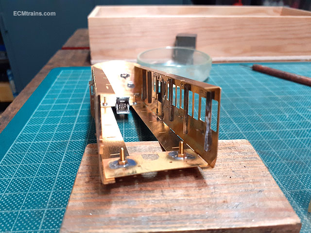
Drop-lights going in after cleaning up the solder on the door hinge parts, the drop-lights go snug up against these so need to check the fit! A .4mm brass pin is used through the door handle hole to hold in place while tack soldering the top with 180deg solder, then after checking the line up the pin is pulled out and the part is soldered up. Done, with a little bit of clean up required. After the cleaning the next step is to test assemble the sides and ends to see how it all fits and make adjustments as required. Then it's set-up on the chassis to prepare to tack solder the sides, ends, and the bolting plates. This will ensure the body will fit the chassis when finally soldered up! The other 3 kits are following along with the same process being done. Happy Christmas to all. Eoin.
-
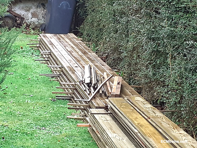
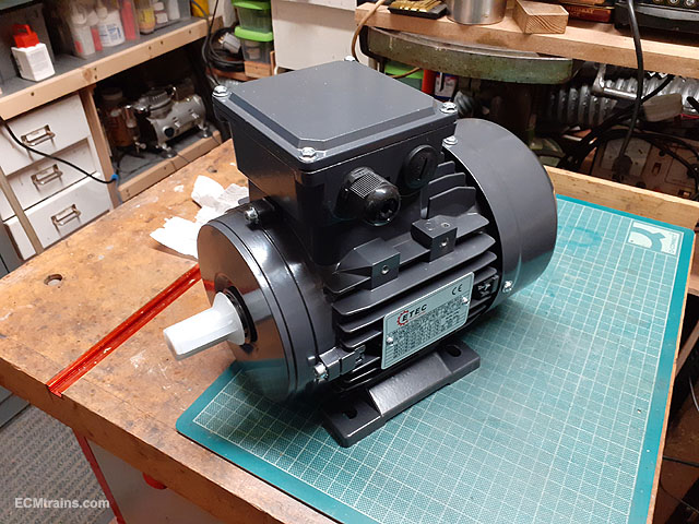
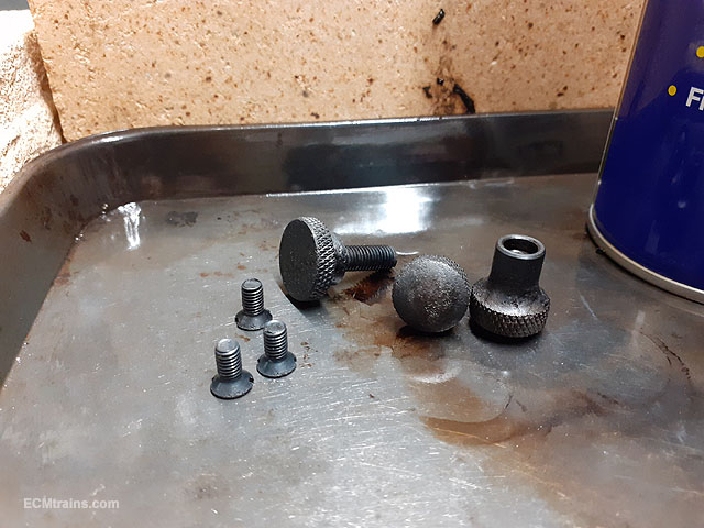
Thanks all for the likes, I wondered if their would be an interest in a thread like this on here........ The riser blocks for the lathe are a bit of a home spun thing! Myford and others do make the original cast iron type but are not available at the moment. So I'm going to modify these so that they will be shorter and fit into the coolant tray I'm going to make for the machine, I need to chop off a small bit at the front and a good chunk at the back. The wood for the 'Lathe Shed' arrived last week, I now have it under wraps to dry out a bit over the Christmas weekend. Also stacked to allow the air circulate. The 1hp 3 phase motor arrived but the inverter is delayed until the new year. A mounting frame will have to be bashed up for the motor as it's mounting holes do not line up on the lathe motor plate, so loads of other stuff to do while waiting for the inverter. The next photos are the sequence of restoring the lathe casing knobs and screws which were originally 'metal blackened'. First the loose rust was removed with wire brush, then chucked into a bath of citric acid for a day. This is how they came out, a bit pitted but sure they'll be grand. Then blackened with heat and oil- sprayed oil on them, heated them up with the blowtorch until almost red, then kept spraying oil on as they cooled down. Smothered in motor oil and popped in a bag to wait for the casing painting to be completed. Eoin
-
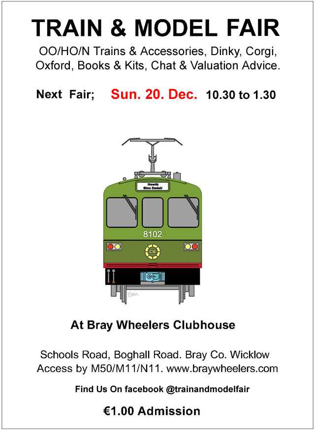
No booking required, do use a mask, we don't expect large numbers but if there is over say 20 people in the room please wait outside until someone exits. The traders will direct the situation if needs be.... Look forward to seeing you there Eoin
-
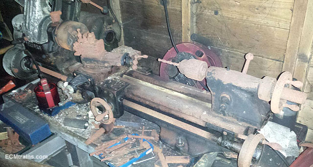
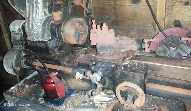
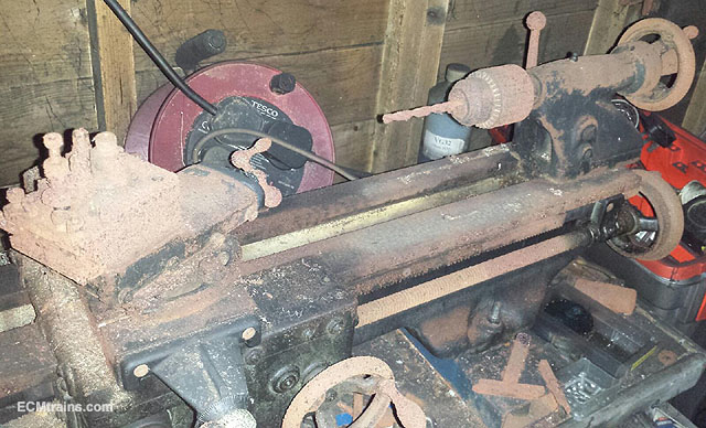
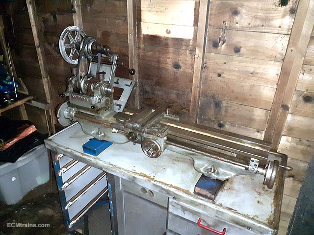
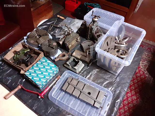
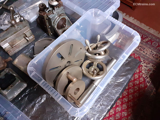
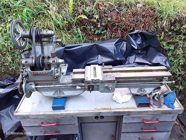
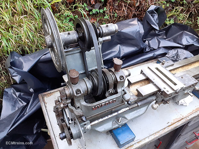
I'm going to show the restoration of this lathe here. It's not a train but it will help to make trains!....... I was offered this lathe at a extremely reasonable price as it was damaged in a workshop fire, fortunately the shed did not burn down completely as the timbers where the fire started charred and protected the remainder. The main damage to the lathe was from smoke and fire acid from plastics and other items that burned! The fire happened a few years ago and the owner was so disappointed with all the destruction he locked the door and rarely went back in. Poor chap, the last thing anyone wants to happen to their workshop! I jumped at it when he offered it to me, I have always had an interest in owning a ML7 or Super7 but they now come at a high price for a good one, especially the Super7. I had bought a mini lathe as that option was far more economical at the time, but now knowing the limits of the mini lathe something bigger was always in the back of the mind. Myford still make parts for these lathes, there is a huge amount of accessories and tooling available for them on engineering sites, Ebay, Banggood, and more. Photos taken when first seen a few months ago..... At that inspection I doused the whole machine with diesel and brushed it in and left it sit for a couple of days. When I returned and gave it a wipe down, then I could get a good look at the damage and decide on doing the deal..... I did! Next step was to move it to my place which entailed lightening the load. The motor, top slide, cross slide, tailstock and a few other items were removed and the machine was then ready for lifting. Looking a bit better now. All the bits were cleaned again with diesel, wire brush, a lot of elbow grease, and then left to soak in citric acid for a few hours. Most parts cleaned up well, but the chrome finished parts had lost their shine and the more one treated them the more shine was lost- so I cut my loses and left the cleaning at a point that with use the parts will shine- I hope. Casings will need a sandblast and a bit of paint. The photos below show the progress on cleaning the bed, it's about 50% done. Items can now be moved without rust tearing the bearing surfaces and to my amazement it's all in fairly good condition. And the first bits with new paint going on. Lower left is the Dixon tool post after cleaning up- slightly pitted from the rust but does work fine! Handles painted. I'm going to upgrade the motor to a 1HP 3 phase motor, controlled by an inverter which will give variable speed control. The original motor is single phase and speed control was by stopping the lathe and changing the drive belt to a different speed pulley- not great, it is doable but the upgrade is a far better option for speed control and it's a far better motor......... Eoin
-
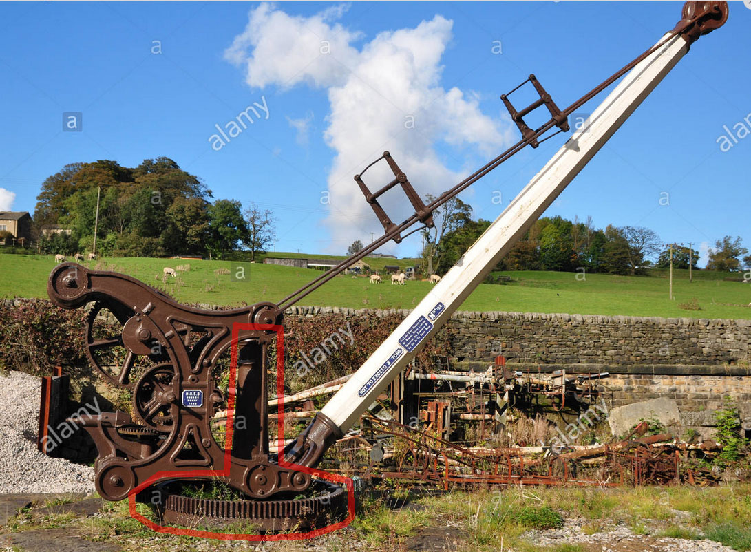
Most cranes were built in England, Turners in Dublin and the loco foundry in Drogheda may have built a few. The best preserved cranes today are on the waterways! and here is a link that has a few photos and some manufacturer's names in England and the North;- https://irishwaterwayshistory.com/about/irish-waterways-furniture/the-machine-demands-a-sacrifice/ I would suggest removing the growth on your find to see if the castings have any markings as to whom may have cast them- doubt it though! manufacturers usually affixed a makers plate on the completed work! The photo of the station above indicates to me that the crane was installed in a poor location- only affording access to one or two wagons in a train, it would have been far more useful located at the other end of the shed which would allow access to a plethora of wagons! Maybe they only needed access to one wagon or the designer thought so? Eoin
-
It's the pivot for a loading crane as JHB says;- https://www.alamy.com/railway-crane-for-goods-oakworth-station-kwvr-image331291350.html?pv=1&stamp=2&imageid=C5433348-B77F-45BE-A690-711B1BF1C036&p=1124238&n=0&orientation=0&pn=1&searchtype=0&IsFromSearch=1&srch=foo%3dbar%26st%3d0%26pn%3d1%26ps%3d100%26sortby%3d2%26resultview%3dsortbyPopular%26npgs%3d0%26qt%3dgoods%20trains%26qt_raw%3dgoods%20trains%26lic%3d3%26mr%3d0%26pr%3d0%26ot%3d0%26creative%3d%26ag%3d0%26hc%3d0%26pc%3d%26blackwhite%3d%26cutout%3d%26tbar%3d1%26et%3d0x000000000000000000000%26vp%3d0%26loc%3d0%26imgt%3d0%26dtfr%3d%26dtto%3d%26size%3d0xFF%26archive%3d1%26groupid%3d%26pseudoid%3d%26a%3d%26cdid%3d%26cdsrt%3d%26name%3d%26qn%3d%26apalib%3d%26apalic%3d%26lightbox%3d%26gname%3d%26gtype%3d%26xstx%3d0%26simid%3d%26saveQry%3d%26editorial%3d1%26nu%3d%26t%3d%26edoptin%3d%26customgeoip%3d%26cap%3d1%26cbstore%3d1%26vd%3d0%26lb%3d%26fi%3d2%26edrf%3d%26ispremium%3d1%26flip%3d0%26pl%3d
-
until
-
GSWR/GSR/CIE Six-Wheeled Coaches - ECMbuild in Gauge OO
murrayec replied to murrayec's topic in ECM Model Trains
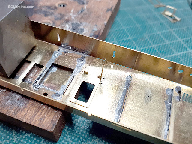
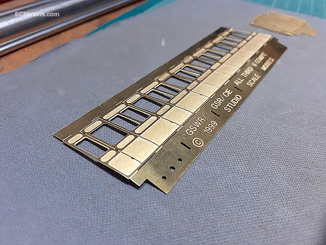
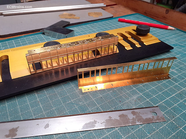
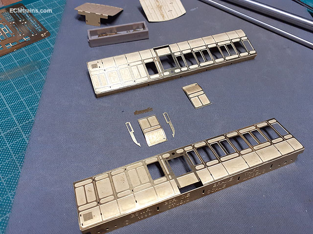
The 6 wheelers are progressing;- Just showing the body build of the Brake 3rd as it's the more complex build the others are the same without the duckets! After cleaning up the cusp edges on all the body parts I bent the tumble home on the sides with 8mm, 10mm rods and the mouse mat. It's not much of a tumble so a push in with the 8mm bar and then rolled with the 10mm bar to flatten slightly until it fitted the ends. Then bent up the top n bottom tabs to 90 deg. Folded up the base taps on the ends, soldered in the footsteps on and the captive nuts on the fixing plates- held in with sticks while soldering. These plates will be soldered on top of the end's tabs but I going to wait until I bolt the lot together before doing that. Setting up the parts for the duckets, the front panel has a reverse curve at the bottom, all bent with the 8mm bar while test fitting it to the sides. Door hinge pieces being soldered in. Hinges on. Ducket sides were first lightly tack soldered at the top tab, then adjusted until the front panel fitted flush with them and then they were fully soldered on the inside. Then the front panel was soldered on from the inside while holding it with a piece of wood in the fingers. A thin soldering bit can just about get in there between the coach sides and the ducket front panel! Panel on with the solder wicking through to the outside, requiring a little clean up later. The base of the panel is also soldered from the inside. The ducket roof was then soldered at it's tabs from the inside, then adjusted to fit the panel on the outside, and then soldered to the panel internally with the little soldering tip. Duckets done. Next up are the drop-lights in the doors and ventilators....... Eoin
-
GSR & CIE locomotive list for grey, green or black livery
murrayec replied to jhb171achill's question in Questions & Answers
Another option in enamel is Humbrol 27 'Matt Sea Grey' -
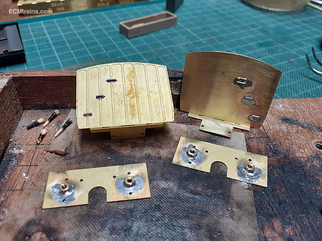
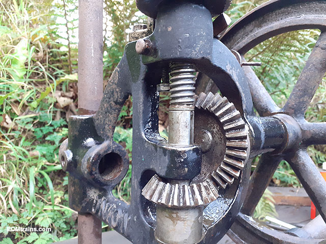
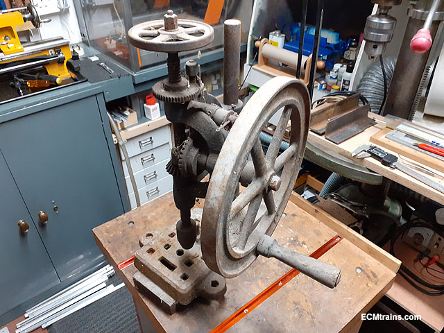
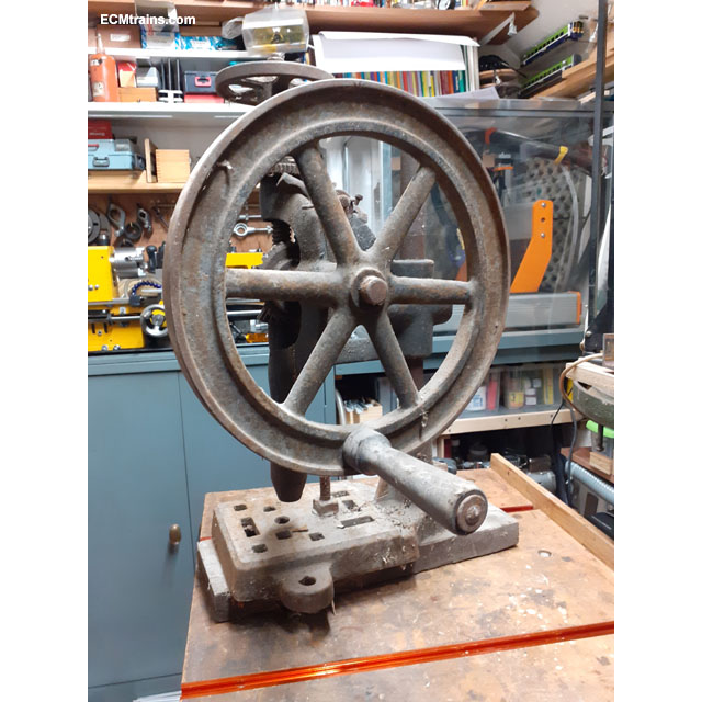
After a good clean down with Gunk and pressure washer things are looking good! There was a good bit of grease on most of the working parts under the dust which preserved most. With a squirt of WD40 and hefty persuasion I got the chuck to turn! The bevel gears are in great condition. There is a ratchet system on the quill which controls the drop of the chuck and an eccentric lobe on the handwheel bevel gear to allow the chuck to be wound back up- one has to slip the lobe follower onto the lobe for this to operate, it's that toothed gear under the top handwheel with the ratchet finger adjacent. The spring to hold the ratchet on the gear is missing and someone installed a bit of grey plastic in its place. All dismantled and ready for a bath! Eoin
-
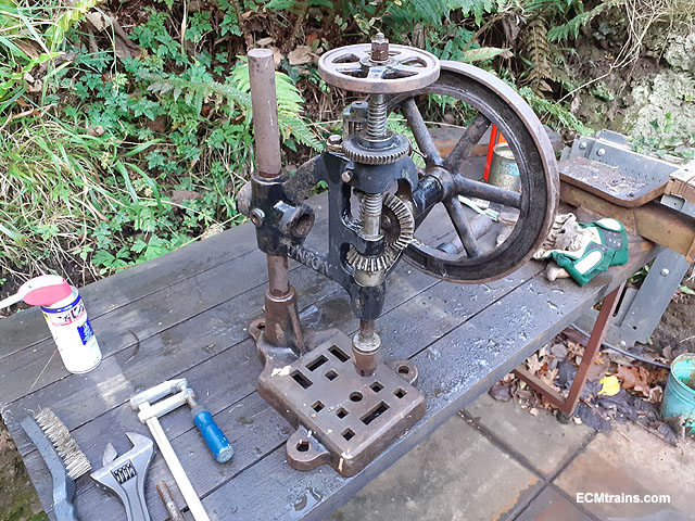
I acquired this Union Drilling Machine for a restoration project and ultimately use it when restored. It's rated at 1PP (Person Power). I used one of these in my silversmith days back in the 70's, it was driven by a belt off the workshop line shaft but one had to turn the handle at the top to drop the drill bit into the work. It's going into a bath of diesel for a few weeks to free the rust up and then restoration. Eoin
-
Money box in the shape of the castle, amazing detail including plants and surrounds. Available exclusively from Blarney Castle. h 10cms, w 7cms, d 7cms. https://store.blarneycastle.ie/products/blarney-castle-money-box
-
Weathering Murphy Models 121 Class Locomotives With Mick Bonwick
murrayec replied to Warbonnet's topic in Tips & Tricks
@jhb171achill Anthony MacDonald (RIP) of the IRRS had related to me some time back the story of the Gray livery 121, unfortunately this cannot be confirmed now, but Anthony was an encyclopaedia of info on the 121 (consulting with Mr Murphy on the development of the 121 model);- '' The manufactures painted the loco in their choice of livery as CIE were hesitant to confirm the livery required! The manufactures made the decision on grey & yellow to stay on program'' Eoin -
Tamiya Air Brush System No.20 With Spray Work Basic
murrayec replied to burnthebox's question in Questions & Answers
It's a single action gun, dual action gun would be better so that one can control the paint flow with the trigger finger! //bartsharpairbrush.co.uk would do a far better starter kit with a dual action gun- for example this compressor & gun kit is £64.00 https://bartsharpairbrush.co.uk/product/bartsharp-airbrush-compressor-kit-tc802/?doing_wp_cron=1605302653.0207669734954833984375 Eoin