J-Mo Arts Posted December 18, 2021 Posted December 18, 2021 27 minutes ago, Killian Keane said: Thats quite interesting, I usually do my stuff around 16 degrees on my Mars, what machine are you using? Elegoo Mars as well (first edition not a Mars 2 or Pro or anything). It doesn't happen all the time, it maybe not be linked to the angle, perhaps a part of my hardware is wearing out and needs replacing. I'm currently out of resin so I need to get done more and work out where the problem is.
David Holman Posted December 18, 2021 Posted December 18, 2021 Sounds fascinating - if only I knew what you were talking about! 1 3
KMCE Posted January 3, 2022 Author Posted January 3, 2022 On 16/12/2020 at 9:47 AM, KMCE said: And now for something Completely Different Been busy with other projects! Another hobby of mine is cabinetry, and I decided to marry the two hobbies together. I find during the winter months I do not get much modelling work done as we light a fire in the living room every evening, and it is much more cosy there than going to to the other room, so i decided to fashion a modern version of the old writing bureau for the living room. The inention is to create a workspace that is shallow (fits into the alcove beside the fireplace) and can be closed away when not in use. At this stage I have got to a fuctional unit without doors as they will require considerable work to finsh. Unit is constructed of Oak (locally sourced) with Oak veneer inlaid panels (commercially sourced) with some Walnut stringing in the uprights for a little decoration. Uprights with Walnut stringing. Machined timber resting on the bench behind. Basic cabinet construction. The design of the cabinet is that it will have doors which open and slide back into the cabinet - the side pockets and hardware visible here. This is to help ensure the weight is not too far forward which may cause the cabinet to tip forward in use; the cabinet is only 400mm deep when closed. A drawer type table top pulls out and acts as the main worktop. Unit was finished in Danish oil and some strip LED lighting added for basic light. Functional unit without doors at this stage, as the doors will require considerable work. I have some very nice Oak Veneer which needs to be flattened & fixed to an MDF substrate before I can compelte the doors - I may get to that over the Christmas break. But for now, I can work in the living room with a cosy fire. Sooo....it's been a year since I posted on this unit, and only got round to completing the doors over the break. Similar construction to the main unit, and mounted on the pocket door hinges which did take considerable adjustment to get the doors level. Pleased at how it has turned out, and nice to be able to close the unit finally. 8 4
David Holman Posted January 4, 2022 Posted January 4, 2022 Yep, proper job. Got to be pleased with that, Ken. 1
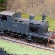
KMCE Posted March 13, 2022 Author Posted March 13, 2022 A while since I posted here, but quite a bit has been going on in the background. At one of the Bray shows I purchased a TMD J26 kit from a very kind gentleman who came over to discuss kits etc. This needed a new chassis as the kit version is too light. Chassis was constructed with hornblocks for centre and front axle to allow compensation. Kit allowed for articulated con rods, and are built up in two layers. What was nice is the kit had a number of number plates with it, and I elected to build as 560 with the extended cab enclosing the bunker as used by the Waterford & Tramore Railway. Nearly complete and spent the day completing the electrics & fettling the running to get some relatively smooth running. Still some work to do, but coming along nicely. Shown along side 423 Class. Really need to touch up the connecting rods - they suffered from repeated on & off handling while fettling the movement. As part of this build, I included the RC electrics I have been converting my locos to over the last while. I have not had a chance to post as I have been spending time on developing the methodology of installation. There is quite a bit of wiring to be done, and this can be hard to hide in a loco, not to mention space for all the various components. For 12V locos the normal solution is to use switch / charging connection, single cell LiPo (Lithium Polymer) battery, voltage regulator, receiver / controller, and connection to motor. Finding space for equipment in 4mm can be challenging and the two most difficult are the battery & switch / charger. The switch charger measures c. 20mm x 10mm and must be screwed in a position to allow access to the charging connection so on smaller tank locos generally means underneath between axles. It's not ideal as it means the loco must be picked up to switch on and off (and charge) for each operating session. For larger tanks and tender locos, this switch can be located in the bunker and covered with a false coal load. The battery (in this case a 250mAh) fits in the boiler barrel and is connected to the switch . This battery measures 35mm long x 15mm wide & 5mm deep. This battery is good for 30 mins or more of constant operation with c. 1 hour charge time. This may seem not a lot of time, but if operating more than one loco on a layout is more than enough. From the battery switch a voltage regulator is needed as the battery voltage is only 3.7V. The down side of using this regulation is that the receiver is not able to establish the condition of the battery - over discharge of a LiPo will render the battery useless, so an additional wire is needed between the transmitter and battery. The receiver is shown behind the regulator. The receiver is quite intelligent and has a number of channels which allows inertia motor control, lights, sound, etc, so whilst not as expansive in operation as DCC, does provide considerable control. There is quite a bit of wiring with these modules, but have done a few now, it does not take much time. It can however prove challenging to hide all the cabling within the loco; I will definitely have to add some crew to hide this. The controller is quite basic and rather old looking, but is capable of controlling 12 locos at one time - this does not mean you are limited to only 12 locos - it is a function of which locos you switch on at the time. Each loco is addressed 1 -12, however the only time you will have a conflict if you try to run two locos with the same address number. This may seem a lot of work, but not having to wire track or worry about lack of pick up, or dirty track is rather nice. Once the loco operates, track condition is no longer a worry - you just need to remember to charge them up before a show. To date I have converted 5 locos & two railcars. The one loco proving very difficult to convert is the 495 Class due to the lack of space - this will most likely be a 6V solution as the receiver is smaller, however battery capacity will be very limited thus reducing operating time - the Drewry petrol railcar operates this 6V solution with a 50mAH battery and is quite limited in operation. All in all, quite a learning experience, but well worth doing. Cost wise from Micron Radio Control: Switch / Charging point - £ 6.00 Voltage Regulator - £5.50 Receiver - £29.00 Transmitter (one off) - £65.00 Battery (ex China) - € 5.00 So from a cost perspective, not excessive for individual loco control. Anyway all for now, Ken 6 3 5
David Holman Posted March 14, 2022 Posted March 14, 2022 Fantastic - thanks for sharing this, Ken. Have been pondering RC on and off for a while, even if only doing a few locos, so that there would always be something to run in a crisis. Has happened to me twice, albeit in over 100 shows - once when a dead short caused a total shutdown for almost and hour and recently when I took Belmullet out and a dodgy controller plug ruined most of the morning on the first day. Getting all the stuff into a 7mm loco ought to be easier than with a small 4mm loco, though am wondering if some of the items need to be bigger, to cope with the larger size/weight? That said,a Mashima 1833 motor gearbox only draws about 0.25 of an amp and my one amp Gaugemaster handheld controller is adequate for all my locos. Definitely something to consider, after all and average exhibition day is about 7 hours, so a mix of conventional and battery power could easily cover that, plus allowing a second/third loco to run without extra wiring. Yes, DCC, does that but have found I just don't get on with it. Fine looking J26 too! 2 1
Galteemore Posted March 14, 2022 Posted March 14, 2022 (edited) That is excellent and inspiring work, Ken. Nice version of a J26. In the 7mm world, r/c is probably the long term future as opposed to DCC, as some prophets are predicting. One exponent is Graham Powell, who produces big engines like this Bulleid, capable of pulling heavy trains at speed on a garden line, quite a challenge for a battery but he swears by the system. He uses a £4.99 motor with a homemade gearbox, too…. For an Irish scheme, an SLNCR railbus with battery and receiver in the trailer could work nicely…..;) Edited March 14, 2022 by Galteemore 1
Mayner Posted March 14, 2022 Posted March 14, 2022 I have been using battery RC on the garden railway for several years, the main advantage is reliability in operation no problems with poor power conductivity outdoors and eliminating the need for wiring. The main issues issue are the "Cottage Industry" nature of railway battery RC manufacture since Aristocraft ceased manufacture in 2013 and relatively short battery life. Aristocraft manufactured the "Crest" battery RC system which was basically the "standard" with a range of transmitters, receivers, batteries and switchgear for American outline battery RC. The 'cottage industry" manufacturers are basically at the mercy of the component manufacturers, which can be challenging if you are trying to standardise on transmitter (Throttle/Hand Held controller) and receivers. (decoders in DCC Terms). I began using RCS an Australian https://www.rcs-rc.com/ manufacture about 7 years ago and currently have 8 battery powered RC locos with 6 different receiver types and 5 Transmitters of 4 different types as earlier transmitter and receivers became obsolete and were no longer available. I use twin 7.2V 1600mh/a NiMH racing car battery packs in locos which were generally good for 1 hour running when fully charged, but have had to replace battery packs after 2-3 years as they batterys struggle to hold a charge or get a train home. I am likely to stick with Analog track power for my kit and scratch built 4mm Irish locos when they are not on the workbench or in the display case 1 2
murphaph Posted March 14, 2022 Posted March 14, 2022 I would have assumed a combination of powered track and RC would make the most sense: 12V or whatever permanent track voltage (don't need to worry about reversing loops being powered or point frogs being correctly polarised, just leave those "complicated bits" completely unpowered. The track can be dirty with unreliable pickup, as long as there's enough power being supplied to keep the on board batteries fully charged, there should be no limitation to run time. The track is just being used as a charging cable basically. 2 1
Noel Posted March 14, 2022 Posted March 14, 2022 16 hours ago, KMCE said: A while since I posted here, but quite a bit has been going on in the background. At one of the Bray shows I purchased a TMD J26 kit from a very kind gentleman who came over to discuss kits etc. This needed a new chassis as the kit version is too light. Chassis was constructed with hornblocks for centre and front axle to allow compensation. Kit allowed for articulated con rods, and are built up in two layers. What was nice is the kit had a number of number plates with it, and I elected to build as 560 with the extended cab enclosing the bunker as used by the Waterford & Tramore Railway. Nearly complete and spent the day completing the electrics & fettling the running to get some relatively smooth running. Still some work to do, but coming along nicely. Shown along side 423 Class. Really need to touch up the connecting rods - they suffered from repeated on & off handling while fettling the movement. As part of this build, I included the RC electrics I have been converting my locos to over the last while. I have not had a chance to post as I have been spending time on developing the methodology of installation. There is quite a bit of wiring to be done, and this can be hard to hide in a loco, not to mention space for all the various components. For 12V locos the normal solution is to use switch / charging connection, single cell LiPo (Lithium Polymer) battery, voltage regulator, receiver / controller, and connection to motor. Finding space for equipment in 4mm can be challenging and the two most difficult are the battery & switch / charger. The switch charger measures c. 20mm x 10mm and must be screwed in a position to allow access to the charging connection so on smaller tank locos generally means underneath between axles. It's not ideal as it means the loco must be picked up to switch on and off (and charge) for each operating session. For larger tanks and tender locos, this switch can be located in the bunker and covered with a false coal load. The battery (in this case a 250mAh) fits in the boiler barrel and is connected to the switch . This battery measures 35mm long x 15mm wide & 5mm deep. This battery is good for 30 mins or more of constant operation with c. 1 hour charge time. This may seem not a lot of time, but if operating more than one loco on a layout is more than enough. From the battery switch a voltage regulator is needed as the battery voltage is only 3.7V. The down side of using this regulation is that the receiver is not able to establish the condition of the battery - over discharge of a LiPo will render the battery useless, so an additional wire is needed between the transmitter and battery. The receiver is shown behind the regulator. The receiver is quite intelligent and has a number of channels which allows inertia motor control, lights, sound, etc, so whilst not as expansive in operation as DCC, does provide considerable control. There is quite a bit of wiring with these modules, but have done a few now, it does not take much time. It can however prove challenging to hide all the cabling within the loco; I will definitely have to add some crew to hide this. The controller is quite basic and rather old looking, but is capable of controlling 12 locos at one time - this does not mean you are limited to only 12 locos - it is a function of which locos you switch on at the time. Each loco is addressed 1 -12, however the only time you will have a conflict if you try to run two locos with the same address number. This may seem a lot of work, but not having to wire track or worry about lack of pick up, or dirty track is rather nice. Once the loco operates, track condition is no longer a worry - you just need to remember to charge them up before a show. To date I have converted 5 locos & two railcars. The one loco proving very difficult to convert is the 495 Class due to the lack of space - this will most likely be a 6V solution as the receiver is smaller, however battery capacity will be very limited thus reducing operating time - the Drewry petrol railcar operates this 6V solution with a 50mAH battery and is quite limited in operation. All in all, quite a learning experience, but well worth doing. Cost wise from Micron Radio Control: Switch / Charging point - £ 6.00 Voltage Regulator - £5.50 Receiver - £29.00 Transmitter (one off) - £65.00 Battery (ex China) - € 5.00 So from a cost perspective, not excessive for individual loco control. Anyway all for now, Ken Very impressed. Respect 1
KMCE Posted March 14, 2022 Author Posted March 14, 2022 Thanks for the comments guys - much appreciated. To respond to a few comments: 12 hours ago, David Holman said: wondering if some of the items need to be bigger, to cope with the larger size/weight? The receiver has the capacity to handle a stall up to 1.3A @13V so should be capable of running your motors From recollection the recommendation is for loads up to a maximum of 1A for this receiver. With the additional space I would go for bigger batteries which would give longer running times (longer charging though) which should get you through a days operation. 9 hours ago, Mayner said: The 'cottage industry" manufacturers are basically at the mercy of the component manufacturers Interesting comment and is probably something I should keep an eye on. I have been dealing with Andy from http://www.micronradiocontrol.co.uk/ who has proved very helpful with advice and providing a complete solution except batteries - he cannot ship LiPo batteries, however he did provide me with contacts to his suppliers in China. The receivers and parts for the transmitter are supplied to him by http://www.deltang.co.uk/. Deltang have been upgrading their receivers, but so far have all been compatible - so no problems so far. 8 hours ago, murphaph said: enough power being supplied to keep the on board batteries fully charged, there should be no limitation to run time I really like this idea. At present not possible with the charge controller I'm using; it's not possible to charge when the power is switched on to the loco. That said, I wonder could an intelligent charge controller be switched using one of the spare switching controls on the receiver - i.e. select the loco with the controller & push a button to disconnect the charging & allow the loco to operate. For me the best place for this charging facility would be in the fiddle yard where there are simple lengths of track, easily cleaned. Locos charged & ready for use on the layout, meaning no wiring needed on the main lines. Regards, Ken 4 1
KMCE Posted March 17, 2022 Author Posted March 17, 2022 So..... Part of what has been going on in the background was the development of Etches for some locomotives - DWWR / DSER, as to be exptected, in this case the 423 Class 2-4-0T (being the most numerous on the DSER line) and its extended version the 428 Class 2-4-2T. Etches arrived back from the excellent people at PPD Scotland, and I decided to build the 423 Class first to ensure the etches are correct. The intention here is to develop kits of both locomotives for both OO and 21mm Gauges. The etches are 0.45 Nickle Silver for the chassis work and 0.3mm Brass for the bodywork. I intent to include 3D printed elements for chimney, smokebox front, dome, safety valves, tank fillers and buffers - all of which have been developed and printed ready for the model. Nothing for it but to get stuck in. Frames were removed from the fret & in this case material removed to allow the 21mm compensated version to be built. The material to be cut out for the hornblocks is substantial enough to allow for a strong fixed chassis version. Frame spacers next and are include three: front with angled plate to take faux cylinder heads, centre spacer with fold down sides to simulate firebox and plain rear. The centre space for the 21mm version has been designed to take the RC switch / charging point alluded to in the posts above. Matching spacers (less the RC Switch cutout) are provided to build the chassis to OO gauge. The 21mm compensated version needs hornblocks and compensation beam. Hornblocks are those from High Level Kits, whilst the compensation beam is included in the etch and is doubled up, sweating the two parts together. Installing hornblocks for compensation between front bogie and leading driver is more difficult that just using the normal axle setup box for coupled axles - the front axle being centered lower than the main drivers. I created a jig which centres on the rear fixed axle and lines up using the brake hangar holes in the chassis. This allowed setting for both hornblocks at the correct height & true. All of this bringing us to a nice rolling chassis. Set up at the moment is on a spare set of EM drivers - correct P4 wheels will be added once all the work & painting is complete. So far, so good. Compensation beam needed only a very minor tweak to get the chassis sitting level. The only minor issue at this stage is the hole in the brake shoe is slightly oversized, so lining up with the hangar was by eye rather that using 0.5mm rod as originally intended. On to the body next..... 6 4
Mayner Posted March 17, 2022 Posted March 17, 2022 (edited) 59 minutes ago, KMCE said: So..... Part of what has been going on in the background was the development of Etches for some locomotives - DWWR / DSER, as to be exptected, in this case the 423 Class 2-4-0T (being the most numerous on the DSER line) and its extended version the 428 Class 2-4-2T. Etches arrived back from the excellent people at PPD Scotland, and I decided to build the 423 Class first to ensure the etches are correct. The intention here is to develop kits of both locomotives for both OO and 21mm Gauges. The etches are 0.45 Nickle Silver for the chassis work and 0.3mm Brass for the bodywork. I intent to include 3D printed elements for chimney, smokebox front, dome, safety valves, tank fillers and buffers - all of which have been developed and printed ready for the model. Nothing for it but to get stuck in. Frames were removed from the fret & in this case material removed to allow the 21mm compensated version to be built. The material to be cut out for the hornblocks is substantial enough to allow for a strong fixed chassis version. Frame spacers next and are include three: front with angled plate to take faux cylinder heads, centre spacer with fold down sides to simulate firebox and plain rear. The centre space for the 21mm version has been designed to take the RC switch / charging point alluded to in the posts above. Matching spacers (less the RC Switch cutout) are provided to build the chassis to OO gauge. The 21mm compensated version needs hornblocks and compensation beam. Hornblocks are those from High Level Kits, whilst the compensation beam is included in the etch and is doubled up, sweating the two parts together. Installing hornblocks for compensation between front bogie and leading driver is more difficult that just using the normal axle setup box for coupled axles - the front axle being centered lower than the main drivers. I created a jig which centres on the rear fixed axle and lines up using the brake hangar holes in the chassis. This allowed setting for both hornblocks at the correct height & true. All of this bringing us to a nice rolling chassis. Set up at the moment is on a spare set of EM drivers - correct P4 wheels will be added once all the work & painting is complete. So far, so good. Compensation beam needed only a very minor tweak to get the chassis sitting level. The only minor issue at this stage is the hole in the brake shoe is slightly oversized, so lining up with the hangar was by eye rather that using 0.5mm rod as originally intended. On to the body next..... Ken Fair play! especially producing kits for an unsung railway like the DWWR/DSER. I have used PPD for over 10 years and they consistently turned out high quality work and resolve problems when they occur. I have basically ceased design and manufacture of etched kits because of the lack of demand and I am focusing on models for my own personal use. Have you looked at a jewelry or precious metal supplier producing lost wax castings direct from a 3D model as opposed to resin casting? The lost wax castings for my 52 Class kit were produce from 3D printed masters as I did not realise that my supplier could produce the wax moulds by 3D printing https://morrisandwatson.com/3d-printing/ Unfortunately I haven't figured out how to form or 'loft' a 3D flare or skirt for a dome or chimney for the 52 Class I also use lost wax castings, when its necessary to produce duplicate or multiple patterns of producing whitemetal or pewter castings of components like springs or axleboxes. Lost wax casting worked out quite reasonable in cost, its possible that businesses in the Ireland and the UK are offering similar services to Morris and Watson. Edited March 17, 2022 by Mayner 1 1 3
KMCE Posted March 18, 2022 Author Posted March 18, 2022 Moving on with the build. Footplate up first. Buffer beams are bent to shape and soldered to the ends. Valances with integrated steps to follow & are soldered into slots provided in the footplate. Additional middle step proved somewhat difficult to solder in place due to its small size - better to fix this in place while the valance is still in the fret. For this model the valances were included in the 0.3mm Brass, and proved to be a little light - I moved these to the 0.45 Nickle Silver sheet for the 428 model, so should be a little more robust. Next element is to double up on the front axle springs. Two layers of springs were sweated together prior to bending up into position. Side tanks are up next. Based on experience from building the first version of this loco, I developed a tank base former to help shaping of the tanks, but also to provide a fixing point to the footplate. Fixing nuts were soldered while the former was on the fret and using the footplate underneath to ensure all lined up. The 423 Class has a band at the bottom which was created by folding back a preformed band from inside to outside. Tank sides were formed using 8mm bar& tweaked to fit the tank top and former. A recess was formed in the side close to the top to set the position just below the top ensuring a consistent step - this should avoid the need to add beading to the tank tops. Tanks thus formed it was on to cab formation. Spectacle frames were added to front and rear cab sheets, while the rivet detail was sweated on to the cab front. Grooves provided on the cab sides help to locate cab front & rears. Bunker rear has a half etched band at the top to allow the curve to be introduced. This should be soldered into place before the cab back is installed due to the lack of space. This cab assembly can then be located on the tanks using the slots provided, while the rear of the cab / bunker is soldered to the tank former. This provides a rigid structure which can then be bolted to the footplate. Band at the base of the tanks mentioned earlier is a little more visible in these shots. Starting to come together nicely. Up next - boiler & smokebox. 8 1
KMCE Posted March 18, 2022 Author Posted March 18, 2022 17 minutes ago, Galteemore said: Looks really well thought out So far so good - some minor tweaks will be required for the release version. Small things like missing holes, or extra holes? A quick check on my drawings & ho-hum, there they are (or not)!!. One element difficult to work out prior to test is how folding will change dimensions. Buffer beams are a fraction oversize and the double fold on the tank base lifted the tanks a fraction up which caused a slight misalignment with the tank former at the rear of the cab. Nothing major, but will be good to get sorted prior to going to press. Generally all going to plan so far. 3
KMCE Posted March 20, 2022 Author Posted March 20, 2022 So - boiler & smokebox today. Boiler was rolled & formers used to maintain the shape. The semi circular formers were used where the boiler is cut away, whilst the full circle used to connect the boiler to the smoke box. NS ring is sized to go outside the boiler & provides the stepdown from the smokebox to the boiler. Very useful in getting the boiler shape right also. I didn't take photos of the smoke box assembly, but this consists of soldering in two brass nuts to the smokebox former to hold boiler to smokebox & smokebox to footplate. The wrapper was sweated on. Another minor error developed here - smokebox wrapper is too short, again probably as a result of miscalculation of the metal bend for the smokebox former. The slight increase in height of the tanks pushed the cab up slightly and resulted in a gap between boiler and cab rivet plate. The angle of the boiler to smokebox also needed some adjustment as they were not in correct alignment further compounding the gap. Some judicious filing of the front of the boiler went part way to solving the problem. As the smoke box wrapper did not quite meet the footplate, I created a saddle detail from some spare fret material which helped to cover the gap. Some locos has this saddle detail, whilst others did not, so I can live with this. As noted I propose to provide 3D printed parts for the loco which included smokebox front, chimney, dome, safety valves, buffers & tank fillers. All except the fillers were added to get an idea of how the loco would look. Final details such as handrails, vacuum pipes etc are to be added, but this was far enough to understand what changes will be needed for a future kit version. Armed with that knowledge, I can tweak the etch drawings to resolve these issues. Turning out to be quite a nice little loco. All for now. Ken 14 1
KMCE Posted March 23, 2022 Author Posted March 23, 2022 And so for the other kit. In this case a 2-4-2T of the GSR 428 Class ex DSER loco. The 428 Class was a rebuild of the 423 Class shown in the earlier posts. Etches, once again in Brass 0.3mm for the body, and Nickle Silver 0.45mm for the chassis. As this and the previous model are based around the same basic structure, albeit with lengthening the body for a larger bunker & the addition of a trailing bogie, the chassis construction is slightly different. Different width spacers are used and grooves in the frames allow a slight narrowing of the chassis to allow front an rear bogies a little more lateral movement. Faux cylinder fronts were added to the front spacer, and the faux firebox with the fold down sides proved to be slightly over-width, so this was cut at the joint, filed to the correct dimension, installed and sides soldered in afterwards. The difference with this kit is that both front and rear axles are held in bogies which will allow greater articulation of the loco on curves and point work - this, and the cant in the chassis being learned from the armoured train chassis built some time ago. Bogies are simple fold up etches with holes reamed out for axles, which are then connected to associated spacers in the frame using 10BA bolts. The compensation beam included in the kit proved to be too short (doh!) which will be addressed in the production kit, and a piece of T shaped brass with a flat pad used instead. I will need to include a phosphor bronze wire to apply some spring pressure to the rear bogie to ensure it sits properly on the track, particularly in reverse. Brakes added as per the previous kit to get to rolling chassis stage. Footplate was constructed as per previous model, however in this case I included the valances and steps in the Nickle Silver etch which has proved to be more robust than the brass of the previous kit - I'll change the 423 kit to accommodate this. Put it all together...... Body to follow, but all for now. Night, night. Ken 8
David Holman Posted March 24, 2022 Posted March 24, 2022 Looking really smart and going at pace too. 2
KMCE Posted March 26, 2022 Author Posted March 26, 2022 So, over the last day or two the body work has progressed. I should have taken more photos, however methodology used for 423 were followed to build the body for 428. Most of the body work went together fine with the minor exception of the bunker rear not being tall enough - it's about 1 - 1.5mm to low - easily fixed in for the production version. For this model, I'll just add some 1mm strip to fill in the gap. This loco has the connections for the RC switch in the bunker, which will in turn be covered by a faux coal load. Rivets were added while the parts were still in the fret which made life a little easier. Body is not fully fixed down at the rear and the black is basically marker used to prevent solder adhering to the footplate below. Quick photo of the two locos extant. Given the two locos are from the same stable, it is possible to swap boiler - probably similar to the prototype! Quick view as to how the loco will look once completed with the associated 3D printed parts. A few issues to resolve with this kit, the main one being the spacing of the bogie to the leading driver - this is a little more than prototype and needs to be brought back. As mentioned earlier, a tweak to the rear bunker is needed to line things up as well as some minor tweaks common to both models. Otherwise very pleased as to how this loco has developed - nice addition to the stable and hopefully brings another forgotten loco back to public perception. All for now. 8 3
Angus Posted March 26, 2022 Posted March 26, 2022 (edited) Very nice KMCE! The curve on those tanks are particularly satisfying, it would have been very easy to get one of them slightly out, and very obvious if it was! Edited March 26, 2022 by Angus 1
KMCE Posted March 26, 2022 Author Posted March 26, 2022 9 minutes ago, Angus said: very easy to get one of them slightly out Agreed. The tank top & tank base help to line everything up. Having built two of these now, I'm thinking it may be better to include the tank base on the 0.45mm NS sheet as the brass is a little flimsy. Ken 3
David Holman Posted March 30, 2022 Posted March 30, 2022 Here's something that might interest you, Ken - a new book by the remarkably talented Giles Favell. Giles has been building radio controlled 7mm scale road vehicles and cranes for several years, but this book shows that he has expanded his portfolio considerably. Starts off with a look at his layouts, then there is a chapter on modern components [and how to source them], before dealing with the construction of individual models. He started off with die cast models of flatbed trucks and vans, graduating to articulated lorries and working cranes. This side of the water, these models feature on a layout called Denton Brook, which notably has several road vehicles wandering around, but also a quite extraordinary working crane lorry. However the book shows he has kept busy with things like a 7mm scale Austin Seven [tiny!], a tipper lorry and even a traction engine. As if that wasn't complex enough there is a fork lift truck, self propelled railway crane and even a 'walking man' - albeit with a hidden mechanism that owes much to ice berg theory. There is also a section on radio controlled locos and he is now producing 4mm scale radio controlled road vehicles... All rather splendid, though I must confess I understand very little of it at the moment! For anyone interested, the book is published by Wild Swan ISBN 978-1-912038-62-6 Amazing models. 4 3
KMCE Posted March 30, 2022 Author Posted March 30, 2022 Oohhh....that looks interesting. I had a look at his website http://bygiles.com/ - seriously impressive, with videos of the operations. His layouts are very realistic & with the addition of operational traffic really brings them to life. I think I may get a copy of that book. Thanks David. 1
David Holman Posted March 31, 2022 Posted March 31, 2022 Think you will understand it all better than me Ken. There is a bit of lathe work, laser cutting and 3D printing involved too - though am sure there are alternatives. The sections on cranes and RC locomotives will hopefully be most use to me. Apparantly, a lot of pioneering work has been going on in Germany, where, apparently you can already buy HO scale RC model cars!! How good/how much have no idea, but another few years and no doubt we will all have AI controlled vehicles scurrying around our layouts. Donkeys, sheep and cattle too, with any luck.
KMCE Posted April 6, 2022 Author Posted April 6, 2022 Second boiler complete. I scratched up a new smokebox sheet as I knew the kit version was too short. I think I will include the second row of rivets towards the bottom of the smokebox as they add good detail and are prototypical. The printed chimney and dome need a little more work - a flare around the base is needed, so back to school on the 3D CAD & creation of complex shapes! In principle the 3D parts are working and are easier to do than white metal, lost wax, or resin casting, so I think it's worthwhile developing the detail. The smokebox fronts have come out very well, and with some added grab rail & hinge bar will finish these nicely - some coordination with the brass will be needed to ensure both fit without the gap. So now back to PPD with the revised version to correct the minor errors & kits will shortly be available. All for now Ken 14 3
leslie10646 Posted April 7, 2022 Posted April 7, 2022 On 14/3/2022 at 7:53 AM, Galteemore said: That is excellent and inspiring work, Ken. Nice version of a J26. In the 7mm world, r/c is probably the long term future as opposed to DCC, as some prophets are predicting. One exponent is Graham Powell, who produces big engines like this Bulleid, capable of pulling heavy trains at speed on a garden line, quite a challenge for a battery but he swears by the system. He uses a £4.99 motor with a homemade gearbox, too…. For an Irish scheme, an SLNCR railbus with battery and receiver in the trailer could work nicely…..;) I must repeat GM's comment - that's all very neat. I first came across radio control when one of my Great Rail Journeys customers invited me to visit his garden railway - all LGB, massive garden, all radio controlled. On arrival, he handed me a walkabout controller, pointed at one of he trains and said "That's your engine" ........ I was sold in no time flat. Ken has gone one stage further with his battery powered motive power - and showed that it needn't cost a fortune - well done that man! 4 1 1
KMCE Posted April 29, 2022 Author Posted April 29, 2022 The rake of tipping wagons completed some time ago have been sitting on the test track looking for couplings to be fitted and a suitable locomotive to haul them. Given the last mineral train departed Avoca in 1900, an earlier style of loco will be needed. Thus the excuse to build a 2-2-2WT loco. DWWR / DSER ran quite a few singles, some of them being quite long lived, and most getting a rebuild at some point in their life. The loco I decided to model was the re-built version of Kate Kearney - an ex Dublin & Kingstown Railway Loco built in 1865, which was rebuilt in 1887 and numbered No. 27. Quite a distinctive loco and quite a number of photos survive in both original and re-built condition. Image courtesy of Shepherd & Beesely - Dublin & South Eastern Railway p82. A CAD drawing was developed from the photo & figured dimensions available of the loco & a cut file generated for the CNC mill. I neglected to take a photo of the chassis cut, but this was assembled to provide a nice rolling chassis. Centre driver is fixed with compensation of leading and trailing axles. Trailing axle is limited in vertical travel by means of 1mm brass strip, while the leading axle is allowed to move with springing provided by some phosphor bronze wire. This set-up allows a relatively stable loco which does not pitch around the centre driver. A this stage no gearbox or intermediate chassis spacers have been installed as I am waiting for some 3.7V motors to arrive so I can develop a battery / motor / gearbox arrangement. The footplate is basic with maximum cut out to allow various motor gearbox combinations. The valance under the footplate is interesting and looks like tanks, so 0.1mm brass sheet was used to allow a tight curve to represent this. I remembered to take some photos of the body elements (in 0.35mm brass) prior to assembly! What is missing above is the proposed smokebox wrapper. I decided to use 0.1mm Brass for this as the 0.35mm was too thick to follow the more complex curves of the smokebox formers - I mean, what could possibly go wrong? Similar to the recent locos, I propose to use 3D printed parts for the smokebox front, buffers, chimney, dome, safety valves and sand boxes. So all this came together to form this.... Hmmmm.....that smokebox wrapper didn't quite work out. It did follow the curves, but is very sensitive to heat & didn't quite settle the way I wanted. So - as the plan was to 3D print the smokebox front, why not print the entire smokebox. That's a bit better. Also this gave the opportunity to print the chimney as part of the smokebox avoiding another joint. I had no drivers suitable for single operation, so I took a cranked driver and printed a new spoked centre - advantage being, I can add the counter weight into the print & kill two birds with one stone - so to speak. The curved valance / tank arrangement is a little more visible in this photo as is the limited view through the splasher - I think I will redo this element as the prototype had a more of a view of the spokes. More work to be done, but promising start. This one will probably be finished in DWWR livery (not looking forward to the lining!) which will be more in keeping with the age of the tipping wagons. I will finish some 3-plank & mineral wagons in DWWR livery also to provide some additional running options. More as progress warrants. Ken 10 8
Galteemore Posted April 29, 2022 Posted April 29, 2022 That is lovely work Ken - nice mix of technologies too. Those singles are a most interesting proposition to get running well, as I know from an MGW one! Lovely looking little engine. 1 1
Killian Keane Posted April 29, 2022 Posted April 29, 2022 Truly exceptional work, Ill be interested to see how you get on balancing the 2-2-2 1
Recommended Posts
Create an account or sign in to comment
You need to be a member in order to leave a comment
Create an account
Sign up for a new account in our community. It's easy!
Register a new accountSign in
Already have an account? Sign in here.
Sign In Now