Galteemore Posted September 2, 2020 Posted September 2, 2020 Looks terrific Ken, especially that last lineside level photo. 1
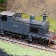
KMCE Posted September 11, 2020 Author Posted September 11, 2020 Bit of weathering done & loads added to the flat wagons. Few more details & we should be there. I kinda figured that the loco would not last too long in works grey so dialled up the dirt on the loco. Material on the wagons is just a random load of timber, sleepers, chairs, chains etc. 9 6
David Holman Posted September 12, 2020 Posted September 12, 2020 Dirty, but still subtle, while the correct track gauge (nicely blasted and painted) makes the whole scene hangs together really well. 1
Buz Posted September 12, 2020 Posted September 12, 2020 HiKMCE What an ugly brutish thing, captured to perfection. Don't leave it there too long or some bloody minded RSM will order it painted post haste. regards John 1
popeye Posted September 12, 2020 Posted September 12, 2020 The whole train looks great, nice work. Would the loco be that light a grey compared to the wagons? 1
jhb171achill Posted September 12, 2020 Posted September 12, 2020 1 hour ago, popeye said: The whole train looks great, nice work. Would the loco be that light a grey compared to the wagons? I'd say this would be a sort of "military" colour, rather than standard GSR grey (which, of course, would be a good bit darker). It's hard to tell from old photos, but much military equipment was of this sort of order, I believe, though others here will know more about military stuff than I would. 1
murrayec Posted September 12, 2020 Posted September 12, 2020 One of Ken's photos posted earlier in this thread;- 5
KMCE Posted September 12, 2020 Author Posted September 12, 2020 (edited) 4 hours ago, jhb171achill said: sort of "military" colour, rather than standard GSR grey My understanding is that it was only finished in works grey and never got a coat of paint. From the few photos I seen, it only ever appears to be in unmarked works grey. I kept the chassis dark, as this came from one of the DSER tanks (No. 64) which was quickly plated in the works to work the train. The wagos appear to be standard DSER 13'6" box wagons with some plated added. There does not appear to be much information on this train, so it's the best interpreation I can come up with. BTW, many thanks to all for their likes and comments. Ken Edited September 12, 2020 by KMCE 4
jhb171achill Posted September 12, 2020 Posted September 12, 2020 5 minutes ago, KMCE said: My understanding is that it was only finished in works grey and never got a coat of paint. From the few photos I seen, it only ever appears to be in unmarked works grey. I kept the chassis dark, as this came from one of the DSER tanks (No. 64) which was quickly plated in the works to work the train. The wagos appear to be standard DSER 13'6" box wagons with some plated added. There does not appear to be much information on this train, so it's the best interpreation I can come up with. BTW, many thanks to all for their likes and comments. Ken If it is intended to be in works grey, it's spot on - I had forgotten, but I did read that somewhere too. 1
KMCE Posted October 21, 2020 Author Posted October 21, 2020 As mentioned in the Port Bréige post, I needed some additional rolling stock for the port, so a quick and easy wagon would be an open, and one I was planning on making was the DSER 7 Ton mineral wagon. These were ex-private wagons bought (or rather sold by Parnell Quariesy) when the work dried up. 12 in total made it through to DSER, GSR nad on to CIE, so quite long lived. Photo courtsey of Shepherd & Beesley book on DSER. Drawing drafted up in CAD and cut files prepared. Cut, grooved and drilled two sets of frets on the mill to allow me make two. A minor error emerged as the original intent was for the outer boards to sit directly on ths side of the flloor, however not allowing for metal thickness meant I had to break the side to install the boards above & below the floor. This is visible in the prototype photo, so maybe this worked out in the end. Some riveting and straps added to provide some detail and we get: Brakes to be added, rinse & repeat for the second and then off to the paint shop. These will be a nice addition to the fleet and given they are quite short will work nicely with the port. I may make a tarpaulin cover for one to differentiate them as part of the shunting puzzle. Futher updates as progress permits. Ken 12
KMCE Posted December 16, 2020 Author Posted December 16, 2020 And now for something Completely Different Been busy with other projects! Another hobby of mine is cabinetry, and I decided to marry the two hobbies together. I find during the winter months I do not get much modelling work done as we light a fire in the living room every evening, and it is much more cosy there than going to to the other room, so i decided to fashion a modern version of the old writing bureau for the living room. The inention is to create a workspace that is shallow (fits into the alcove beside the fireplace) and can be closed away when not in use. At this stage I have got to a fuctional unit without doors as they will require considerable work to finsh. Unit is constructed of Oak (locally sourced) with Oak veneer inlaid panels (commercially sourced) with some Walnut stringing in the uprights for a little decoration. Uprights with Walnut stringing. Machined timber resting on the bench behind. Basic cabinet construction. The design of the cabinet is that it will have doors which open and slide back into the cabinet - the side pockets and hardware visible here. This is to help ensure the weight is not too far forward which may cause the cabinet to tip forward in use; the cabinet is only 400mm deep when closed. A drawer type table top pulls out and acts as the main worktop. Unit was finished in Danish oil and some strip LED lighting added for basic light. Functional unit without doors at this stage, as the doors will require considerable work. I have some very nice Oak Veneer which needs to be flattened & fixed to an MDF substrate before I can compelte the doors - I may get to that over the Christmas break. But for now, I can work in the living room with a cosy fire. So normal service will resume shortly!! Ken 15
Galteemore Posted December 16, 2020 Posted December 16, 2020 Beautiful, Ken. My grandfather apprenticed as a cabinetmaker in H and W shipyard in the 20s and looking at examples of his workmanship over the years has given me a lasting appreciation of the craft. That is a lovely piece of work. 1 1
David Holman Posted December 16, 2020 Posted December 16, 2020 Clever and very classy. Every home should have one! 1
jhb171achill Posted December 16, 2020 Posted December 16, 2020 2 hours ago, David Holman said: Clever and very classy. Every home should have one! Only one? 2
KMCE Posted December 19, 2020 Author Posted December 19, 2020 On 16/12/2020 at 7:28 PM, jhb171achill said: Only one? Now, now folks........form an orderly (and socially distacned) queue! 1
KMCE Posted December 19, 2020 Author Posted December 19, 2020 Now that I have a practically complete cabinet to work with, I decided to finish off the mineral wagons. The previous buffers were too long for the model, so I got some others from Dart Castings which are a little more prototypical. So buffers changed, brakes added I had one wagon complete. Rinse & repeat completed the second and now we have two DSER (ex Parnell Quarries) 7 ton mineral wagons ready for paint. Some painting and weathering needed to finish them off. Then perhaps a load in one, with the other empty? All for this post. Ken 11 1
KMCE Posted December 22, 2020 Author Posted December 22, 2020 So....... What started off as research into DSER ( & DW&WR) wagons led to the HMRS who have a series of wagon drawings from the Metropolitan Railway Carriage & Wagon Co (MCW). I purchased a series of images in digital format from them for various wagons, one of which being a ballast wagon. From my own research, it appears these wagons were built in 1863 for the DW&WR, however the information provided in the excellent books by Messrs Shepherd (and Beesley) is a little unclear on this. Ballast wagons were ordered in 1856, however MCW only came into existance as company in 1863, so this earlier order must be discounted. From the Shepherd & Beesley account it appears ballast wagons were converted old mineral stock, or second hand wagons from other providers; thus more research will be required to tie down the provenance of both drawings and contemporary records. Anyhow, the HMRS drawings were imported into CAD and drawn up, however some inconsistancies between figured dimensions and drawn information needed to be resolved. Being an engineer, I went for the figured dimensions and amended the drawings accordingly - nothing major, but worth tidying up nonetheless. The drawings developed: Very nice looking wagons with a 6' wheelbase and a 12' x 8' loading area - this scales down to an overall length (over buffers) of 58mm. Buffers on one end only with dumb buffers on the other. Given the simplicity of the model, I decided to go the etch route to produce these, as one / two ballast wagons are not much good. Johh@Mayner in one of his posts advised that PPD Ltd were good to work with for etching, so I worked with their drawing rules and developed a master etch. Given these wagons are so small, it made sense to put 4 of them onto a single sheet to maximise the return on the effort & costs. PPD have been good to work with and whilst initially advising they could not return the etches before Christmas, I got a very nice early present to myself in the post - one complete etch for 4 wagons. These are very much based on brass Origami to create chassis & body, some additional elements were included for in the etch also to provide detail. Some minor errors have resulted both from my drawings & the limitations of etching, however it should be possible to build these and get a feel for how they go together. Cast elements will be requried for axleboxes & springs and I have some Dart Castings which should do, however it may be necessary to turn (and cast) some buffers given they are so small. So now, a nice little Christmas project shall commence. More as updates warrant...... BTW, Happy Christmas to one and all. Ken 9
David Holman Posted December 23, 2020 Posted December 23, 2020 Fascinating and excellent stuff, Ken! 1 1
TimO Posted December 26, 2020 Posted December 26, 2020 Hi Ken, I don’t know much about the origins of the MCW but is it possible the order was placed in 1856 with one of the constituent companies and the photos were given a later date. I have seen this postulated for other drawings in the HMRS archive. I am very impressed with your cabinetry and your etches. Looking forward to seeing how the ballast wagons turn out. 1
jhb171achill Posted December 26, 2020 Posted December 26, 2020 On 22/12/2020 at 11:36 PM, KMCE said: So now, a nice little Christmas project shall commence. Fascinating stuff, and very interesting research. Looking forward to seeing this develop! Happy Christmas! 1
KMCE Posted December 26, 2020 Author Posted December 26, 2020 Well the Christmas project has commenced, and progressed rather nicely. There are some problems with small elements of the detail which became apparent as I built; nothing major, but if I order another etch, I will make some changes. First up, axle holes were reamed out to take waisted point bearings for the axles. Rivets were punched through using the holes as guides. Then began the fold up of the side of the chassis which is where the first gotcha showed up. I didn't allow for the final wrap aound on the chassis ends to close the box - not a big problem, spare fret material was used to fill the gaps. In a future etch I will add a tab to close this out. The w-irons were folded down till they reach the chassis which renders them at 90 deg to the chassis & thus in the correct position. This model is developed for 21mm spacing, however by moving wheels in on the axles an OO version could be made. We now have a basic rollling chassis. W-iron ties, axleboxes and springs were added to complete the rolling element of the chassis, however the brakes were not added as some additional spacing will be required to get the lever and brake block in the correct spaces. I had not allowed for this in the etch, so some remedial work will be requried. Chassis end sections with hook & plate detail added to finish the chassis element. The details for the side straps were included in a former to hold them in place for soldering on to the side. This work is much easier when the body etch was flat. Once the straps were in place, the tabs were trimmed & former removed. All that was needed now was for the double fold on the side to create inner & outer detail, and then folded up 90 deg to form the side. Rinse & repeat for the otherside and the main section of the body is complete. The body ends were formed in the same way and soldered into place. I allowed location holes in the floor and chassis to allign the body, which then allowed for the accurate positioning of the ends with relation to the chassis front & rear. The body can then be fixed to the chassis to arrive at a rolling unit. As noted above, the holes in the chassis box at each end were filled with spare sections of fret. The next gotcha was the strapping for ends - these were held by tabs either side, rather than top & bottom which resulted in them distoring out of shape when trying to remove them from the fret & clean up. I decided to revert to scratch built straps with rivets embossed, but that's for another post. For now, I'll leave it with a photo of the wagon with 423 to give an idea of size. More as progress warrants. Ken 9 3
Galteemore Posted December 26, 2020 Posted December 26, 2020 Lovely neat work Ken and a nice little prototype. 1 1
David Holman Posted December 27, 2020 Posted December 27, 2020 Really interesting to read about the trials of kit design, but (assuming you are using it as an aid to scratch or batch building) certainly shows the value of this approach and definitely something to think about. Ideal models for a small space layout too - am guessing three of these would barely take up the space of two 'standard' wagons. The fine work, as ever! 1
KMCE Posted December 27, 2020 Author Posted December 27, 2020 OK.. As alluded to above, the strap detail for the ends was too light to remove and tidy without distortion, so I fashioned straps from 1mm brass with rivets added. This allowed me to complete the ends and move on. The prototype has a nice metal retainer holding the sides on which was shaped up from 0.5mm wire, however the end loops are a little oversize, but should look OK from a distance. More of an effect than strict adherence to prototypical. Buffers were turned down from old loco axles which were too short for 21mm gauge which rendered the short buffers rather well. Brake detailing was sorted by separating the lever from the brake block and suporting the brake block on a length of 1mm strip with a hole drilled to line up with the suport bracket. This allowed the brake lever to be installed more in line with prototypical. So, wagon complete and more to do. If I am to re-run the etch, I will need to make some small changes to allow detailing strips to be used rather than my time punching rivets. Few other minor changes should sort future runs. Final image with 423 leading.... Some couplers & off to the paint shop and introduce to the other rolling stock!! All for now. Ken 7
David Holman Posted December 27, 2020 Posted December 27, 2020 Some very nice 'gingerbread' there. Excellent detailing - should there be a coin or some such to give scale to the pictures?
KMCE Posted December 28, 2020 Author Posted December 28, 2020 4 hours ago, David Holman said: should there be a coin or some such to give scale to the pictures? Very good idea. For context the €1 coin is the same diameter as a £1 Coin. Hopefully this puts it in perspective? Ken 6 2
KMCE Posted June 7, 2021 Author Posted June 7, 2021 As many have noted herein, no heritage Irish train would be complete without the ubiquitous cattle wagons. I wanted to model the DSER version, alas there are very few images of these, however with a few photos and some calculations based on similar wagons, I managed to develop a suitable model. Rather than make these in brass & face the fiddly build of the uprights again & again, I looked at 3D printing them. The model progressed through various versions till we get this First model, bit to thin... Some developement through rev 2 - timber uprights were still a little thin and not enough definition on the planks..... Another revision, we get to a more presentable model: Holes included in the model did need some reaming out but make the installation of the bars easier. Some tidying up needed - more visible in the photos than on the model itself. Plan is to build a chassis in brass with some added weight to match the weight of the other wagons, but hopefully this should allow me build a rake much quicker. More as time permits. 9 1
murrayec Posted June 7, 2021 Posted June 7, 2021 Excellent Ken, And Snap! I have been working up the drawings for the same project in Gauge O..... Eoin 2
Recommended Posts
Create an account or sign in to comment
You need to be a member in order to leave a comment
Create an account
Sign up for a new account in our community. It's easy!
Register a new accountSign in
Already have an account? Sign in here.
Sign In Now