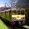
murrayec Posted January 25, 2018 Posted January 25, 2018 Hi I have set up for building Gauge N 141/181 last year, the drawing work is now complete and a few Cameo paper cuttings have been done to adjust the lines, work out the folds, and prepare for the 3D detail. My options are open to construct the body in etched brass or Xerox Laser Printed sheet (like the DART), the brass will require painting and the Xerox wont- so if I can get the Xerox to work to an acceptable level all liveries will be available! I'm using a Kato generic chassis for this one, but I'm held up waiting for the order to be delivered- 4 months now! Here are a few photos of one of the test Cameo paper cuttings assembled up;- As you can see the front windows & panels required adjustment in the drawing, the next step is to complete the lower section of the body, then cut one out in plastic card and see what I have- not enough hours in the day! These will be available as RTR or as a kit There are a few other Gauge N Irish types getting the same treatment- D301, 071, 121, & J15........ Eoin 7 2
jhb171achill Posted January 25, 2018 Posted January 25, 2018 Wow!!!!!!!!! This is the start!!! RTR N gauge will be a dream come true for many! 2
Railer Posted January 25, 2018 Posted January 25, 2018 Will be keeping a very keen eye on this myself. Looking forward to seeing the fruits of this labour. 1
skinner75 Posted January 25, 2018 Posted January 25, 2018 Very nice - I'll be looking forward to future posts on this thread! 1
Dave Posted January 25, 2018 Posted January 25, 2018 Very nice Eoin, paper engineering at it's finest! 1
Noel Posted January 25, 2018 Posted January 25, 2018 Great stuff. Very interesting Eoin. Really looking forward to watching this evolve over time and the end result. 1
murrayec Posted January 25, 2018 Author Posted January 25, 2018 2 hours ago, Noel said: Great stuff. Very interesting Eoin. Really looking forward to watching this evolve over time and the end result. Yes Noel I'm looking forward to it myself- I have a Modular Gauge N layout of Dun Laoghaire station developing up and will be needing a few of these for the DART introduction era section of the layout- does that confuse? The layout is designed to be adaptable, in this era we call it 'Multimedia', the layout will span the main developments of the station from the 1830's to DART introduction in 1980's- more confused? Eoin 1
MikeO Posted January 25, 2018 Posted January 25, 2018 I would be interested in the RTR options as getting the right donor chassis is, I find, exceptionally difficult. The only one I would not be interested in is the D301. MikeO 1
RedRich Posted January 25, 2018 Posted January 25, 2018 Best of luck with this venture Eoin and fair play for opening up a path for N Gauge modellers of our fantastic railway. Judging by what you are producing now they will no doubt be top models. Much respect, Rich, 2
murrayec Posted January 25, 2018 Author Posted January 25, 2018 2 minutes ago, MikeO said: I would be interested in the RTR options as getting the right donor chassis is, I find, exceptionally difficult. The only one I would not be interested in is the D301. MikeO Ah MikeO D301 is a fantastic yoke! may have been responsible for the UK's Class 08 Yes the chassis will be a problem with the footplate on the 141 and 071! I think some modification will be required but not got one yet to hack.... Eoin 1
Irishrailwayman Posted January 27, 2018 Posted January 27, 2018 On 25/01/2018 at 5:18 PM, murrayec said: Yes Noel I'm looking forward to it myself- I have a Modular Gauge N layout of Dun Laoghaire station developing up and will be needing a few of these for the DART introduction era section of the layout- does that confuse? The layout is designed to be adaptable, in this era we call it 'Multimedia', the layout will span the main developments of the station from the 1830's to DART introduction in 1980's- more confused? Eoin Multi-era layout perhaps? 1
MikeO Posted January 28, 2018 Posted January 28, 2018 Eoin Have you considered a BR Class 20 chassis for the 121 class. Class 20 is 90mm long being about 10mm longer than the 80/81mm length for a true scale class 121. With regard to the class 141/181 a Hobby Train Vossloh G 2000 BB is 103mm long again it is over by about 13mm for a true scale 141 which should be about 90mm. The Hobby Train version H2954 has cabs at both ends and wire hand rails between both cabs. A BR class 37 chassis is about 122mm long roughly the right size for a class 071 which is around 117mm for a true scale length . making a suitable body may require the cabs to be made wider in width to allow for a 2mm width walk way between each cab. MikeO
murrayec Posted January 28, 2018 Author Posted January 28, 2018 (edited) Hi MikeO Thanks for info I have a BR Class 20 chassis I've looked at, the 121 & 141 scale body works out at 82mm so this chassis needs a bit of work, as you say it needs about 10mm taken off it. I'm well capable of modify this, but if I sell the model as a self build kit most would not, that is why I'm investigating the use of a new generic off the shelf Kato or Tomix chassis, though this is proving difficult on getting supply! On the 071 the BR Class 37 looks possible, I have a few, but I'm way behind on the body drawings for this! and will not be able to get at it for some time, I also want to hold off until I prove my ideas on the 141 build- Xerox sheet body or will it be brass and have to paint? The 141 body artwork has gone off to the printers to try the Xerox laser print, for colour test, cut test, and to see if it folds up to an acceptable level! Here is an inkjet test print of the 141 1980's CIE livery;- Eoin Edited January 28, 2018 by murrayec 1
Noel Posted January 28, 2018 Posted January 28, 2018 Eoin, have you considered making any of the bodies very slightly longer or shorter than scale length so they might be a snug fit for a popular RTR chassis which out the need to cut metal?
murrayec Posted January 28, 2018 Author Posted January 28, 2018 Noel I'm surprised with you 10mm at this scale is the length of a 141 cab! Eoin
Mayner Posted January 28, 2018 Posted January 28, 2018 .Eoin I might be worth looking at the Lifelike SW9/1200 or Micritrain SW1500 switcher chassis for a B141 Class. Altas produce a MP15 which has a longer frame than the SW locos. I used the old Atlas/Rivarossi SW1500 switcher as a chassis for a plasticard B141 and a pair of 121s about 40 years ago, from memory the SW1500 chassis was pretty close in terms of overall length. 1
murrayec Posted January 28, 2018 Author Posted January 28, 2018 Hi John I had an SW9/1200 in my fist recently and thought it would work and then promptly forgot about it! Thanks for the reminder Eoin
MikeO Posted January 30, 2018 Posted January 30, 2018 Eoin As the Class 20 chassis is 10mm too long for a class 121 would the extra length suit a class 141/181 body. I think the class 121 is about 12.15m long while the class 141/181 is about 13.42m long. The extra 10mm being taken up by the second cab. Mayner The SW9 chassis is, in my experience, near impossible to get hence my suggestion of the class 20 which are currently more plentiful. Is the Atlas/Rivarossi SW1500 any easier to get? MikeO 1
Peter Posted January 30, 2018 Posted January 30, 2018 I'd be very interested in Irish RTR or kit in N gauge. I'll be keeping an eye on this thread. 1
murrayec Posted February 1, 2018 Author Posted February 1, 2018 (edited) Hi Guys The first test print on the Xerox sheet was in from the printers this evening, the tan colour was way off into the orange area, and the chequer-plate on the footplate way to bright- a few small adjustments required and then another test. Anyway I stuck it into the Silhouette Cameo cutting machine and all went well, lined up first time and I got this out The holes for the lights and handrails are spot on their positions, but a bit on the large size A few adjustments will be required to the cutting line but the only mess is on the ladders and the cab side window mullions. I'll still try and fold this up and see how that works before I go back for the second test print- maybe more adjustments will be needed. On the chassis- I have drawn up a 1015 Mashima motor bogie with flywheel, and belt & pulley drive, with a PCB board chassis plate, this idea is being developed up for the Walker build in 4mm I'm doing, but the idea can be implemented here, I think, I hope A bit of origami is now required...... Eoin Edited February 1, 2018 by murrayec 4
Noel Posted February 1, 2018 Posted February 1, 2018 Will watch this facinating development with keen interest. Super work as always from this engineer. 1
WRENNEIRE Posted February 1, 2018 Posted February 1, 2018 2 hours ago, Noel said: Will watch this facinating development with keen interest. Super work as always from this engineer. Thought he was (is) an Architect ? And theres as s in fascinating man, standards are dropping people!!! 2
RedRich Posted February 1, 2018 Posted February 1, 2018 Between the Dart's, the A class bogies, the Greystones project and many other projects on the go I can't imagine where you find the time Eoin to post your work on our group. Add to this your private life outside modelling and it makes it even harder to credit. I appreciate your different threads on here and thank you for always keeping us up to date and sharing your work with us. This is really looking exciting for n gauge modellers. Rich, 3
murrayec Posted February 1, 2018 Author Posted February 1, 2018 (edited) Ok, so did a bit of sticking together tonight, defo needs adjustment all over- it's like etching, it needs a magic number added or subtracted to all panels depending on which way the bend goes. So here are a few photos of the attempt- though a lot of info gleaned from this;- It is looking good for the Xerox sheet idea, I'm not going any further with this assembly, I'll wait until I modify the drawing and test print again.... and here is a sketch of the motor bogie idea, the yellow shading is the PCB chassis plate Eoin Edited February 1, 2018 by murrayec 4
jhb171achill Posted February 1, 2018 Posted February 1, 2018 The cardboard one alone is worth having! 1
Noel Posted February 2, 2018 Posted February 2, 2018 1 hour ago, WRENNEIRE said: Not bad for an Architect That's just his profession. In the real world he is de facto a model engineer supreme - that makes him an engineer too. 2
murrayec Posted February 27, 2018 Author Posted February 27, 2018 (edited) Hi Guys While waiting for the revised body test prints to come back I set about completing the bogie design and started into prototyping it on the CNC machine. The design is more or less as the above sketch in the previous post, I decided to run the axles in the brass sides without wheel bearings to aid assembly, if using bearings the drive gears on the axles and wheels have to removed to assemble and disassemble. So .4mm brass was chosen to provide a wide running surface for the axles with a brass keeper plate screwed on under to keep the axles in place. The pulley drive system makes it difficult to install a standard coupler socket, so I've come up with an out-up-around the pulley affair off the bottom front of the bogie frame with a PB spring to retain the coupler that hopefully will allow the required coupler movement- assembly will tell if this works! Drawing exported as a CNC script and away it goes;- 1mm end mill does a nice job on cutting out the outline of the parts, unfortunately I got my settings wrong for drilling the holes and broke the end mill drilling the first hole. The above is the motor bogie complete, halfcut lines, tabs and open sockets for folding up on assembly Above are the completed parts, the motor bogie and keeper plate came out fine, but the motor-less one suffered from incorrect cut depth on the holes. The red 3M glue used to stick the brass to the MDF backing really did its job, very hard to get the parts out! A slight offset happened on the holes and the halfcut lines- stupidly I removed the spindle from the machine to replace the broken end mill! I do know never to do this but being annoyed at getting the script wrong I just didn't think about it..... I'll have to do it again as these parts wont go together square. 34 minutes total cutting time, but this can be speeded up. I reckon milling is faster than etching- in the drawing work and the cutting, no cusp to remove except a little burr to remove on the edges , just milling- your limited to size of the tool and internal corners are round. Very happy with these results, I'm going to stick with milling and see how assembly goes. Eoin Edited February 27, 2018 by murrayec 7 3
RedRich Posted February 28, 2018 Posted February 28, 2018 Really fantastic and hugely interesting watching this develop Eoin. Rich, 1
Peter Posted March 4, 2018 Posted March 4, 2018 Keep up the good work. Stick me on the order list ;-) 1
Recommended Posts
Create an account or sign in to comment
You need to be a member in order to leave a comment
Create an account
Sign up for a new account in our community. It's easy!
Register a new accountSign in
Already have an account? Sign in here.
Sign In Now